manuals.online logo
Brands
  1. Home
  2. •
  3. Brands
  4. •
  5. BEGA
  6. •
  7. Outdoor Light
  8. •
  9. BEGA 71 601 User manual

BEGA 71 601 User manual

Other BEGA Outdoor Light manuals

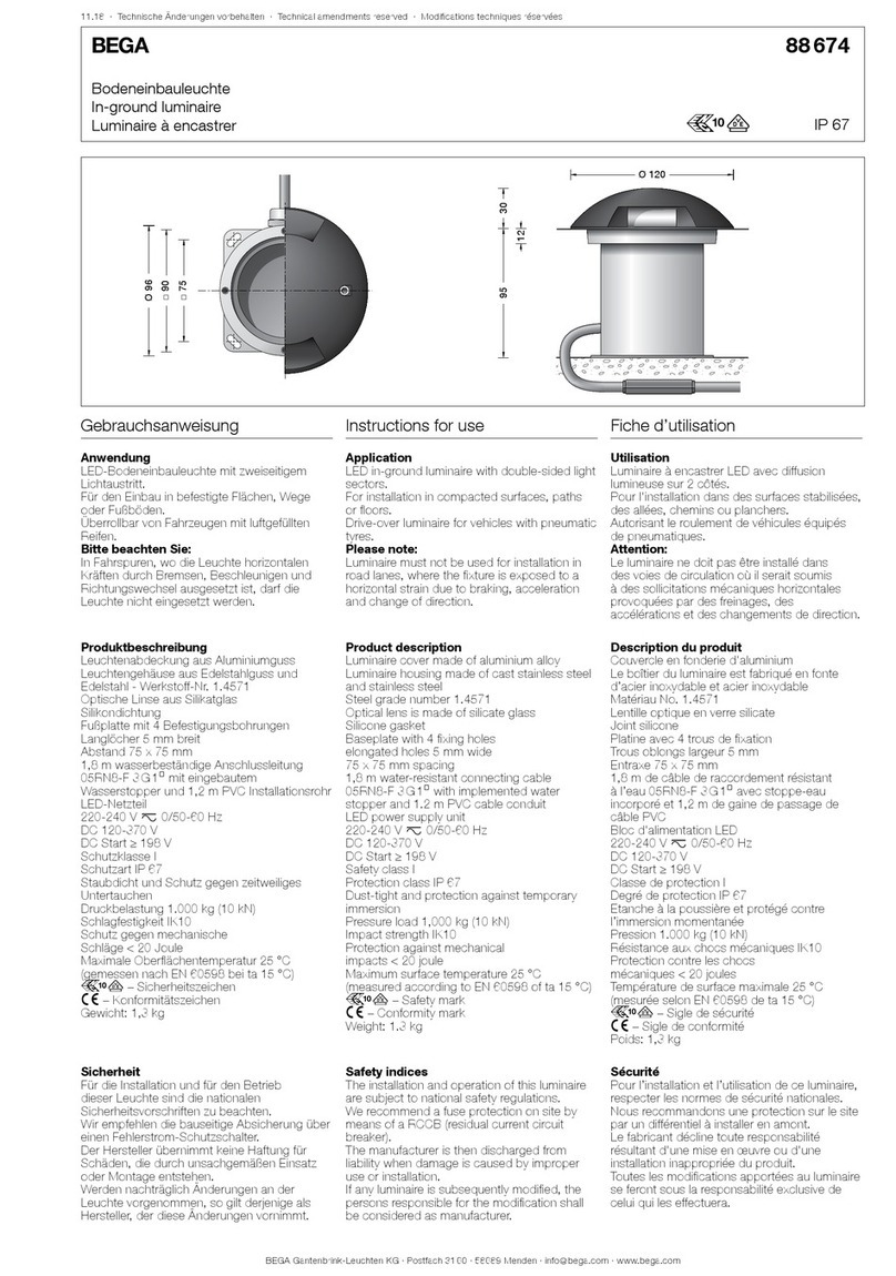
BEGA 88 309 Manual

BEGA

BEGA 88 309 Manual

BEGA 84 992 User manual

BEGA

BEGA 84 992 User manual

BEGA 77 127 User manual

BEGA

BEGA 77 127 User manual

BEGA 84 433 User manual

BEGA

BEGA 84 433 User manual

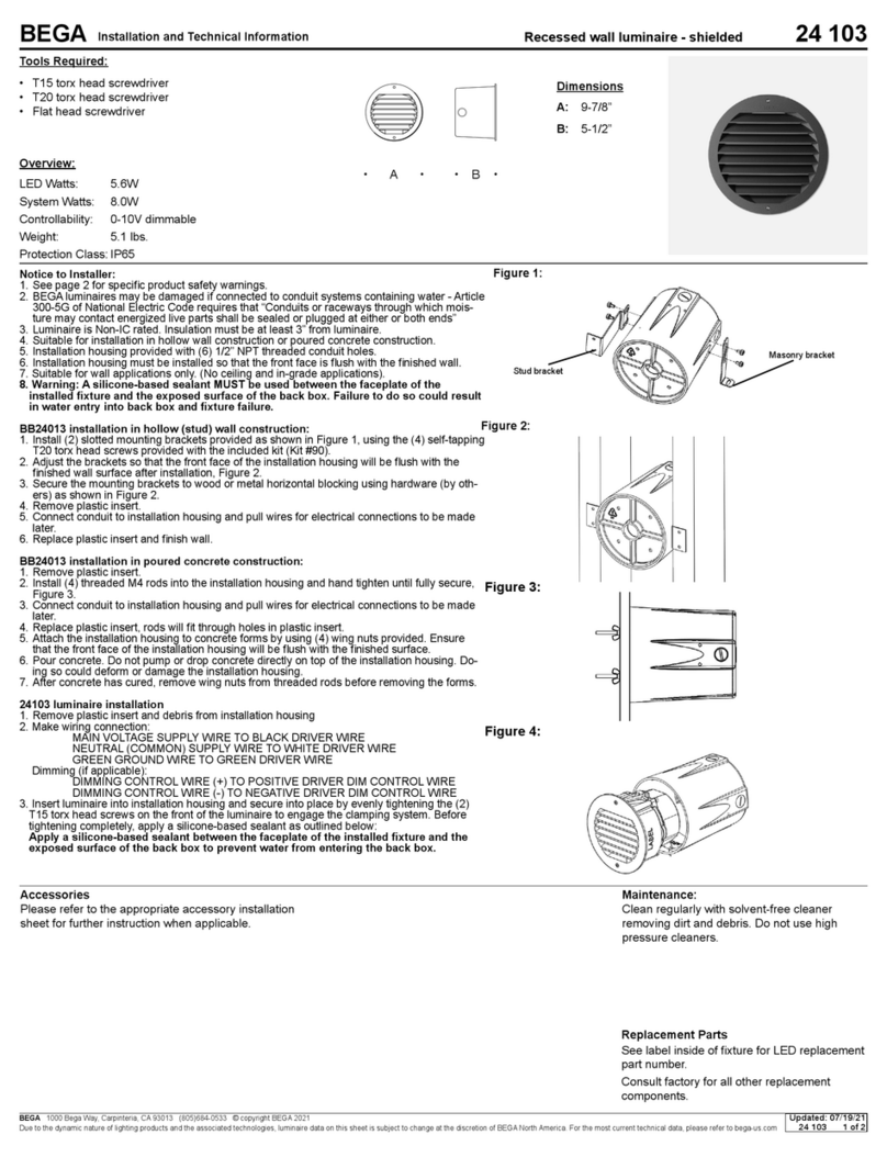
BEGA 24 103 Manual

BEGA

BEGA 24 103 Manual

BEGA 99 636 User manual

BEGA

BEGA 99 636 User manual

BEGA 7264 User manual

BEGA

BEGA 7264 User manual

BEGA UniLink 84 919 User manual

BEGA

BEGA UniLink 84 919 User manual

BEGA 84 730 User manual

BEGA

BEGA 84 730 User manual

BEGA 98 006 Manual

BEGA

BEGA 98 006 Manual

BEGA Kopenhagen User manual

BEGA

BEGA Kopenhagen User manual

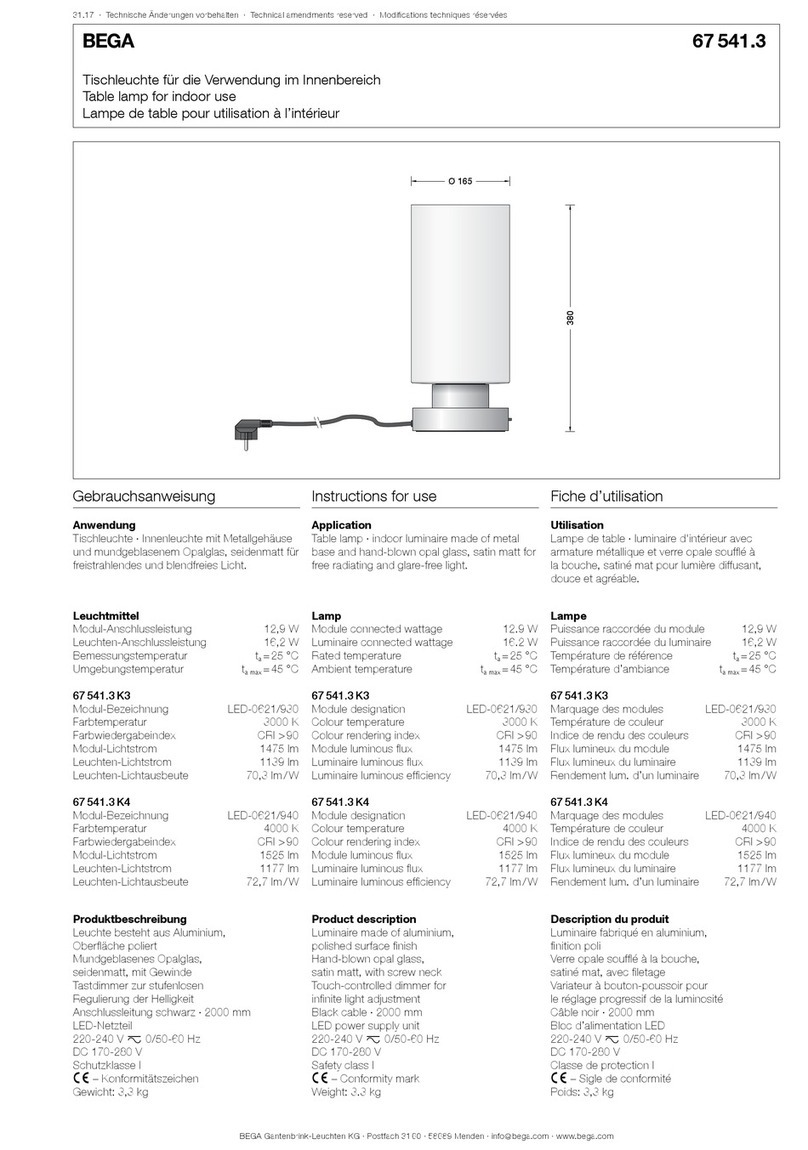
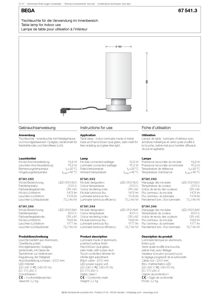
BEGA 67 541.3 User manual

BEGA

BEGA 67 541.3 User manual

BEGA 33 160 Series User manual

BEGA

BEGA 33 160 Series User manual

BEGA 84 563 Manual

BEGA

BEGA 84 563 Manual

BEGA Strassburg User manual

BEGA

BEGA Strassburg User manual

BEGA 84 462 Manual

BEGA

BEGA 84 462 Manual

BEGA 33 386 User manual

BEGA

BEGA 33 386 User manual

BEGA 84415 Manual

BEGA

BEGA 84415 Manual

BEGA 24 210 Manual

BEGA

BEGA 24 210 Manual

BEGA 84 422 User manual

BEGA

BEGA 84 422 User manual

BEGA 33 165 User manual

BEGA

BEGA 33 165 User manual

BEGA 77 146 User manual

BEGA

BEGA 77 146 User manual

BEGA 22 052 Manual

BEGA

BEGA 22 052 Manual

BEGA 24 063 Manual

BEGA

BEGA 24 063 Manual

Popular Outdoor Light manuals by other brands

Kichler Lighting HELEN 37536 instructions

Kichler Lighting

Kichler Lighting HELEN 37536 instructions

Thorn OXANE L installation instructions

Thorn

Thorn OXANE L installation instructions

esotec Solar Globe Light multicolor 20 operating instructions

esotec

esotec Solar Globe Light multicolor 20 operating instructions

mitzi HL200201 ELLIS Assembly and mounting instructions

mitzi

mitzi HL200201 ELLIS Assembly and mounting instructions

HEPER TILA S AFX 3 Module Installation & maintenance instructions

HEPER

HEPER TILA S AFX 3 Module Installation & maintenance instructions

Designplan TRON 180 installation instructions

Designplan

Designplan TRON 180 installation instructions

Sealey LED37 instructions

Sealey

Sealey LED37 instructions

nordlux VEJERS Mounting instruction

nordlux

nordlux VEJERS Mounting instruction

SImx ELITE LED LHTC637 installation instructions

SImx

SImx ELITE LED LHTC637 installation instructions

GEV CAROLINE 10833 manual

GEV

GEV CAROLINE 10833 manual

WE-EF PFL540 LED Installation and maintenance instructions

WE-EF

WE-EF PFL540 LED Installation and maintenance instructions

HEPER DOGO Side LW6048.585-US Installation & maintenance instructions

HEPER

HEPER DOGO Side LW6048.585-US Installation & maintenance instructions

HEPER LW8034.003-US Installation & maintenance instructions

HEPER

HEPER LW8034.003-US Installation & maintenance instructions

HEPER MINIMO Installation & maintenance instructions

HEPER

HEPER MINIMO Installation & maintenance instructions

LIGMAN BAMBOO 3 installation manual

LIGMAN

LIGMAN BAMBOO 3 installation manual

Maretti TUBE CUBE WALL 14.4998.04 quick start guide

Maretti

Maretti TUBE CUBE WALL 14.4998.04 quick start guide

Maxim Lighting Carriage House VX 40428WGOB installation instructions

Maxim Lighting

Maxim Lighting Carriage House VX 40428WGOB installation instructions

urban ambiance UQL1273 installation instructions

urban ambiance

urban ambiance UQL1273 installation instructions

manuals.online logo
manuals.online logoBrands
  • About & Mission
  • Contact us
  • Privacy Policy
  • Terms and Conditions

Copyright 2025 Manuals.Online. All Rights Reserved.

BEGA Gantenbrink-Leuchten KG · Postfach 31 60 · 58689 Menden · info@bega.com · www.bega.com
40.16 · Technische Änderungen vorbehalten · Technical amendments reserved · Modications techniques réservées
IP 55
!
Anschlusskasten
Connection box
Boîte de connexion
71 601
2
5555 6565
230230
245245
Gebrauchsanweisung Instructions for use Fiche d’utilisation
Anwendung
Anschlusskasten für den Einbau in Lichtmaste.
Application
Connection boxe for installation in luminaire
poles.
Utilisation
Boîte de connexion à installer dans le mâts.
Produktbeschreibung
Anschlusskasten gemäß
DIN 43 628/ VDE 0660 · Teil 505
Gehäuse besteht aus
schlagzähem Kunststoff
Brandschutz nach UL94-V2
Gehäusedeckel mit Schraubbefestigung
2 Befestigungslanglöcher ø 6,5 mm
Abstand 232 mm
für den Einbau in Maste ø > 70 mm
Türgröße ab 65 x 250 mm
3 Kabeleinführungen mit zweiteiliger
Kunststoffdichtung und integrierter
Zugentlastung für Erdkabel 5 x 4@
2 Leitungseinführungen mit Dichtnippel für
Leuchtenanschlussleitung 5 x 2,5@
1 Sicherungshalter mit Schraubkappe
für Schmelzsicherung Neozed D 01 bis 16 A
mit eingesetzter Sicherung Neozed D 01 6 A
Schutzklasse II 2
Schutzart IP 55
Staubgeschützt und Schutz gegen
Strahlwasser
c – Konformitätszeichen
Gewicht: 0,2 kg
Product description
Connection box according to
DIN 43 628/ VDE 0660 · Part 505
Housing made of impact synthetic plastic
Fire protection according to UL94-V2
Housing cover with screw mounting
2 elongated xing holes ø 6.5 mm
Spacing 232 mm
for installation in poles ø > 70 mm
Door size from 65 x 250 mm
3 cable entries with two-part plastic gasket
and integrated strain-relief for underground
cable 5 x 4@
2 cable entries with compression nipples for
luminaire connecting cable 5 x 2,5@
1 fuse holder with screw cap for fuse Neozed
D01 up to 16 A
equipped with fuse Noezed D01 6 A
Safety class II 2
Protection class IP 55
Dust-tight and protected against water jets
c – Conformity mark
Weight: 0.2 kg
Description du produit
Boîte de connexion selon
DIN 43 628/ VDE 0660 - Partie 505
Boîtier fabriqué en matière plastique
résistant aux chocs
Protection contre le feu selon UL94-V2
Couvercle du boîtier vissé
2 trous de xation diamètre ø 6,5 mm
Entraxe 232 mm
pour l'installation dans les mâts ø > 70 mm
Dimensions de la porte 65 x 250 mm
3 entrées de câble avec joint en plastique en
deux parties et collier anti-traction intégré pour
câble réseau 5 x 4@
2 entrées de câble de raccordement avec
nipple d'étanchéité pour câble du luminaire
5 x 2,5@
1 porte fusible avec bouchon leté pour fusible
Neozed D 01 jusqu'à 16 A avec fusible intégré
Neozed D 01 6 A
Classe de protection II 2
Degré de protection IP 55
Protection contre la poussière et les jets d’eau
c – Sigle de conformité
Poids: 0,2 kg
Sicherheit
Für die Installation und für den Betrieb
dieses Anschlusskastens sind die nationalen
Sicherheitsvorschriften zu beachten.
Der Hersteller übernimmt keine Haftung für
Schäden, die durch unsachgemäßen Einsatz
oder Montage entstehen.
Werden nachträglich Änderungen an dem
Anschlusskasten vorgenommen, so gilt
derjenige als Hersteller, der diese Änderungen
vornimmt.
Safety indices
The installation and operation of this connection
box are subject to national safety regulations.
The manufacturer is then discharged from
liability when damage is caused by improper
use or installation.
If any connection box is subsequently modied,
the persons responsible for the modication
shall be considered as manufacturer.
Sécurité
Pour l’installation et l’utilisation de ce boîte de
connexion, respecter les normes de sécurité
nationales.
Le fabricant décline toute responsabilité
résultant d'une mise en œuvre ou d'une
installation inappropriée du produit.
Toutes les modications apportées au boîte
de connexion se feront sous la responsabilité
exclusive de celui qui les effectue.
BEGA Gantenbrink-Leuchten KG · Postfach 31 60 · 58689 Menden · info@bega.com · www.bega.com
Montage
Masttür entriegeln und herausnehmen.
Anschlusskasten auf C-Schiene befestigen.
Schraube lösen und Gehäusedeckel
abnehmen. Befestigungsschrauben der
Kabelschelle lösen und Schellenoberteil mit
Dichtungseinsatz herausnehmen.
Schellenober- und Schellenunterteil
entsprechend der Anzahl und des
Durchmessers der Zugangskabel anpassen.
Zugangskabel abisolieren und so einlegen,
dass der Außenmantel mindestens 5 mm in
den Anschlusskasten hineinragt.
Bitte beachten Sie:
Bei nur einem Zugangskabel ist dieses immer
links einzuführen.
Schellenoberteil mit Dichtung und integrierter
Zugentlastung montieren.
Schutzleiterverbindung herstellen und
elektrischen Anschluss vornehmen.
Anschlusskasten schließen.
Tür einsetzen und verriegeln.
Installation
Unlock access door and remove.
Mount connection box on C-clamp.
Undo screw and remove housing cover.
Undo xing screws of the cable clamp and
take out upper part of cable clamp with gasket
insert.
Adapt upper and lower part of the cable clamp
according to the number and diameter of the
mains supply cables.
Strip mains supply cable and insert it in such
a way that the cable sheathing is led at least
5 mm into the connection box.
Please note:
In case of only one mains supply insert it
through the left sided opening of the cable
clamp. Assemble upper part of the cable clamp
with gasket and integrated strain-relief.
Make the earth conductor connection and
the electrical connection.
Close the connection box.
Install the door and lock it.
Installation
Déverrouiller la porte du mât et retirer.
Fixer la boîte de connexion sur le rail de
montage.
Desserrer la vis et ôter le couvercle.
Desserrer les vis de xation du collier de câble
et retirer la partie supérieure du collier avec le
joint. Ajuster la partie supérieure et la partie
inférieure du collier en fonction du nombre et
du diamètre des câbles d'alimentation.
Dénuder le câble d'alimentation et insérer le
de façon que la gaine extérieure pénètre d'au
moins 5 mm dans la boîte de connexion.
Attention :
Quand un seul câble de raccordement est
utilisé, il doit être inséré à gauche.Installer le
collier du câble avec le joint et collier anti-
traction intégré.
Mettre à la terre et procéder au
raccordement électrique.
Fermer la boîte de connexion.
Installer et fermer la porte.