manuals.online logo
Brands
  1. Home
  2. •
  3. Brands
  4. •
  5. BEGA
  6. •
  7. Outdoor Light
  8. •
  9. BEGA 22 228 Manual

BEGA 22 228 Manual

Other BEGA Outdoor Light manuals

BEGA 99 326 User manual

BEGA

BEGA 99 326 User manual

BEGA 22 052 Manual

BEGA

BEGA 22 052 Manual

BEGA 84 218 Manual

BEGA

BEGA 84 218 Manual

BEGA 22 202 Manual

BEGA

BEGA 22 202 Manual

BEGA 84 724 User manual

BEGA

BEGA 84 724 User manual

BEGA 84 314 User manual

BEGA

BEGA 84 314 User manual

BEGA 7264 User manual

BEGA

BEGA 7264 User manual

BEGA 84 137 User manual

BEGA

BEGA 84 137 User manual

BEGA 24 011 Manual

BEGA

BEGA 24 011 Manual

BEGA 98 006 Manual

BEGA

BEGA 98 006 Manual

BEGA 55013 User manual

BEGA

BEGA 55013 User manual

BEGA 24 353 Manual

BEGA

BEGA 24 353 Manual

BEGA 84 326 User manual

BEGA

BEGA 84 326 User manual

BEGA 84 699 User manual

BEGA

BEGA 84 699 User manual

BEGA 84 875 Manual

BEGA

BEGA 84 875 Manual

BEGA UniLink 84 824 User manual

BEGA

BEGA UniLink 84 824 User manual

BEGA 24 013 Manual

BEGA

BEGA 24 013 Manual

BEGA 88 619 User manual

BEGA

BEGA 88 619 User manual

BEGA 84 666 User manual

BEGA

BEGA 84 666 User manual

BEGA 84 433 User manual

BEGA

BEGA 84 433 User manual

BEGA 84 061 Manual

BEGA

BEGA 84 061 Manual

BEGA 84 462 Manual

BEGA

BEGA 84 462 Manual

BEGA 88 674 User manual

BEGA

BEGA 88 674 User manual

BEGA 84 020 User manual

BEGA

BEGA 84 020 User manual

Popular Outdoor Light manuals by other brands

Kichler Lighting HELEN 37536 instructions

Kichler Lighting

Kichler Lighting HELEN 37536 instructions

Thorn OXANE L installation instructions

Thorn

Thorn OXANE L installation instructions

esotec Solar Globe Light multicolor 20 operating instructions

esotec

esotec Solar Globe Light multicolor 20 operating instructions

mitzi HL200201 ELLIS Assembly and mounting instructions

mitzi

mitzi HL200201 ELLIS Assembly and mounting instructions

HEPER TILA S AFX 3 Module Installation & maintenance instructions

HEPER

HEPER TILA S AFX 3 Module Installation & maintenance instructions

Designplan TRON 180 installation instructions

Designplan

Designplan TRON 180 installation instructions

Sealey LED37 instructions

Sealey

Sealey LED37 instructions

nordlux VEJERS Mounting instruction

nordlux

nordlux VEJERS Mounting instruction

SImx ELITE LED LHTC637 installation instructions

SImx

SImx ELITE LED LHTC637 installation instructions

GEV CAROLINE 10833 manual

GEV

GEV CAROLINE 10833 manual

WE-EF PFL540 LED Installation and maintenance instructions

WE-EF

WE-EF PFL540 LED Installation and maintenance instructions

HEPER DOGO Side LW6048.585-US Installation & maintenance instructions

HEPER

HEPER DOGO Side LW6048.585-US Installation & maintenance instructions

HEPER LW8034.003-US Installation & maintenance instructions

HEPER

HEPER LW8034.003-US Installation & maintenance instructions

HEPER MINIMO Installation & maintenance instructions

HEPER

HEPER MINIMO Installation & maintenance instructions

LIGMAN BAMBOO 3 installation manual

LIGMAN

LIGMAN BAMBOO 3 installation manual

Maretti TUBE CUBE WALL 14.4998.04 quick start guide

Maretti

Maretti TUBE CUBE WALL 14.4998.04 quick start guide

Maxim Lighting Carriage House VX 40428WGOB installation instructions

Maxim Lighting

Maxim Lighting Carriage House VX 40428WGOB installation instructions

urban ambiance UQL1273 installation instructions

urban ambiance

urban ambiance UQL1273 installation instructions

manuals.online logo
manuals.online logoBrands
  • About & Mission
  • Contact us
  • Privacy Policy
  • Terms and Conditions

Copyright 2025 Manuals.Online. All Rights Reserved.

Installation and Technical Information
BEGA
Accessories
Please refer to the appropriate
accessory installation sheet for
further instruction when applicable.
In the interest of product improvement, BEGA reserves the right to make technical changes without notice.
Replacement Parts
BEGA 1000 Bega Way, Carpinteria, CA 93013 (805)684-0533 Fax (805)566-9474 www.bega-us.com © Copyright BEGA-US 2019
Surface wall w/ cutoff optics 22 228
Tools Required:
3mm hex key
Standard medium screw driver
Phillips screw driver
Protection Class: IP65
Weight: 1.5 lbs.
Dimensions
A: 4-3/4 ”
B: 4-3/4 ”
C: 2-3/4 ”
Relamping/Maintenance
Disassemble faceplate. Clean dirt and deposits from
the luminaire and glass using only solvent-free
cleaners. Relamp and replace gasket if damaged.
Reassemble faceplate.
Lamp: 3.0W LED 24V DC
22 228
01/31/2019
Page 1 of 2
Description
Faceplate
Gasket
LED Driver (24V DC)
LED Module (3000K)
LED Module (4000K)
Part No
FP2228
831032
75928
74038
74043
Notice to Installer for 22 228:
1. No relamping required.
2. In conformance with UL Standard 1598, a silicone based sealant must be used
between xture and supporting wall.
3. Requires a 24V DC class 2 electronic power supply to operate intended LED
wattage.
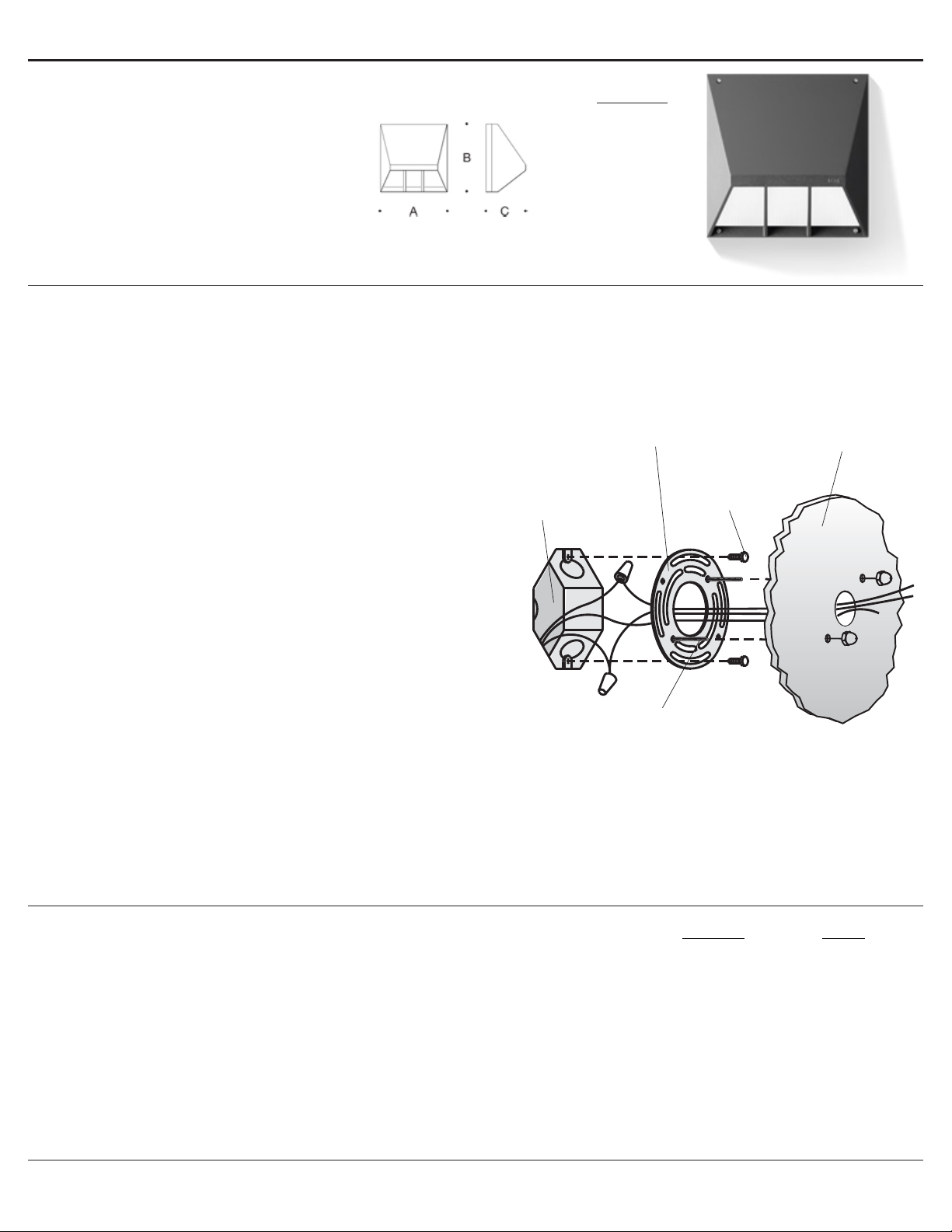
22 228 Installation:
1. Loosen the (3) M4 socket head screws on the luminaire top and remove top from
the luminaire base.
2. Loosen the (2) M4 socket head screws on the base to remove the electrical plate
from the base. However, keep the luminaire wiring routed through the wireway of
the luminaire base.
3. Attach the adaptor ring from the mounting kit to a 3-1/2” or 4” octagonal wiring box
using the (2) wiring box screws.
4. Make supply wiring and luminaire wiring connections inside the wiring box.
NEGATIVE SUPPLY WIRE TO BLACK LUMINAIRE WIRE
POSITIVE SUPPLY WIRE TO RED LUMINAIRE WIRE
5. Test to make sure the luminaire base will be level when installed by aligning the
mounting holes on the luminaire base with the holes in the adaptor ring. Adjust the
adaptor ring if needed.
6. Place a small bead of silicone around the back side of the luminaire ange that will
come in contact with the nished wall (exterior applications only).
7. Secure the luminaire base to the adaptor ring and nished wall by using the (2)
countersunk screws provided.
8. Replace electrical plate.
9. Replace luminaire top and tighten screws evenly
mounting
plate or
luminaire
base
adapter
plate
wiring
box
screws
3-1/2 or 4
standard
octagonal
wiring box
(by others)
mounting screws
Remote 25W LED driver and box 19 580
Remote 50W LED driver and box 19 591
Installation and Technical Information
BEGA
In the interest of product improvement, BEGA reserves the right to make technical changes without notice.
BEGA 1000 Bega Way, Carpinteria, CA 93013 (805)684-0533 Fax (805)566-9474 www.bega-us.com © Copyright BEGA-US 2019
Surface wall w/ cutoff optics 22 228
22 228
01/31/2019
Page 2 of 2
Product Safety Warnings:
THIS PRODUCT MUST BE INSTALLED IN ACCORDANCE WITH THE APPLICABLE INSTALLATION CODE BY A PERSON
FAMILIAR WITH THE CONSTRUCTION AND OPERATION OF THE PRODUCT AND THE HAZARDS INVOLVED.
SUITABLE FOR WET LOCATIONS.
MIN 60°C SUPPLY CONDUCTORS.
CE PRODUIT DOIT ÊTRE INSTALLÉ SELON LE CODE D’INSTALLATION PERTINENT, PAR UNE PERSONNE QUI CONNAÎT
BIEN LE PRODUIT ET SON FONCTIONNEMENT AINSI QUE LES RISQUES INHÉRENTS.
CONVIENT AUX EMPLACEMENTS MOUILLÉS.
LES FILS D’ALIMENTATION 60°C MIN.