Installation and Technical Information
BEGA
Due to the dynamic nature of lighting products and the associated technologies, luminaire data on this sheet is subject to change at the discretion of BEGA North America. For the most current technical data, please refer to bega-us.com
BEGA 1000 Bega Way, Carpinteria, CA 93013 (805)684-0533 © copyright BEGA 2022
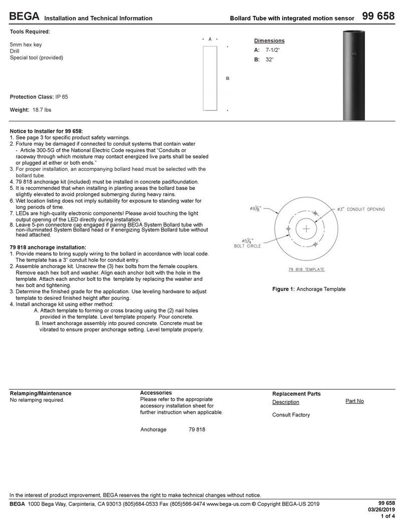
Figure 1: Mounting Diagram
Overview:
LED Watts: 11.9W
System Watts: 14.0W
Controllability: 0-10V, TRIAC & ELV dimmable
Weight: 4.0 lbs.
Protection Class: IP65
Tools Required:
• Hex Tool (3mm)
• Socket Set (4mm)
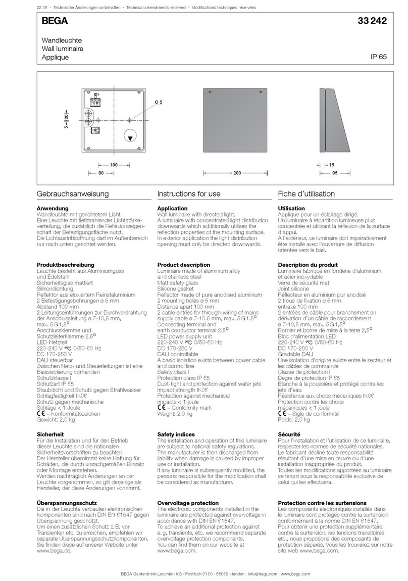
Ceiling and wall luminaire - Unshielded with safety guard · synthetic 24 358
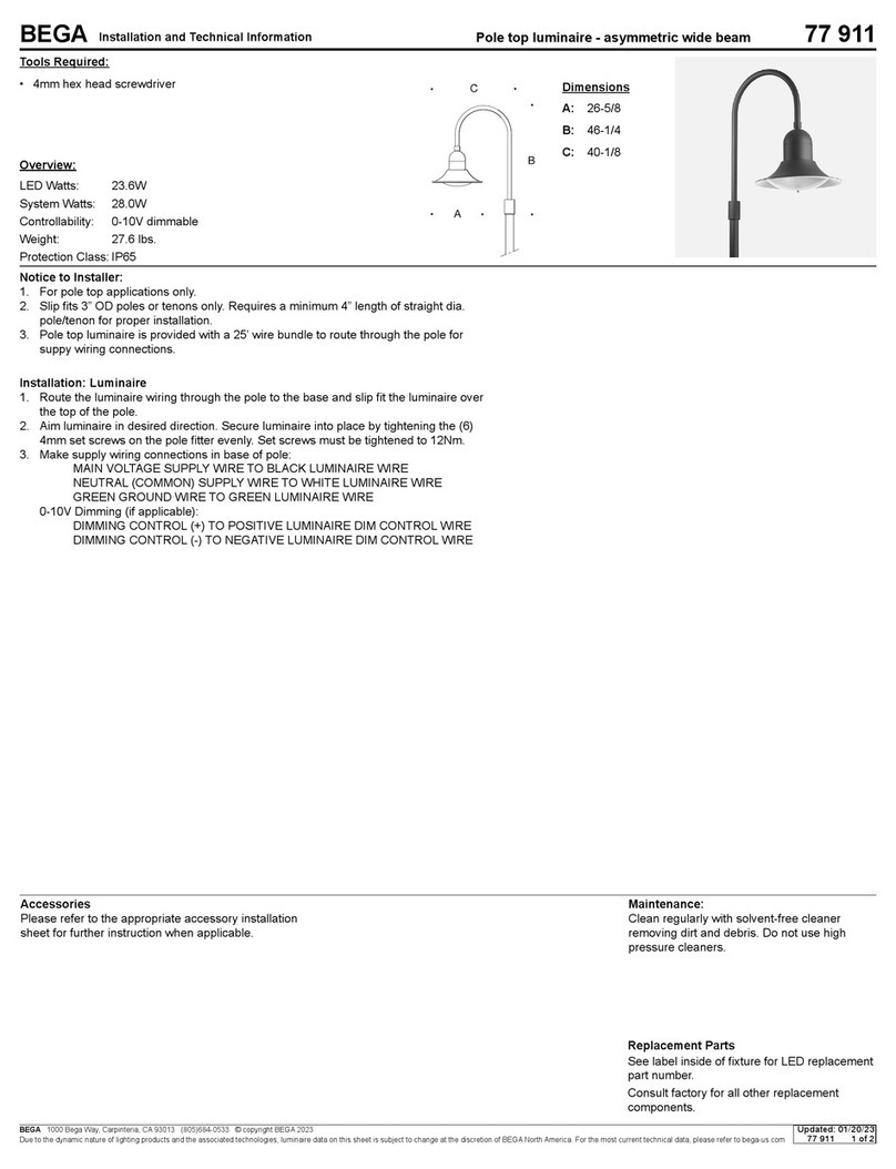
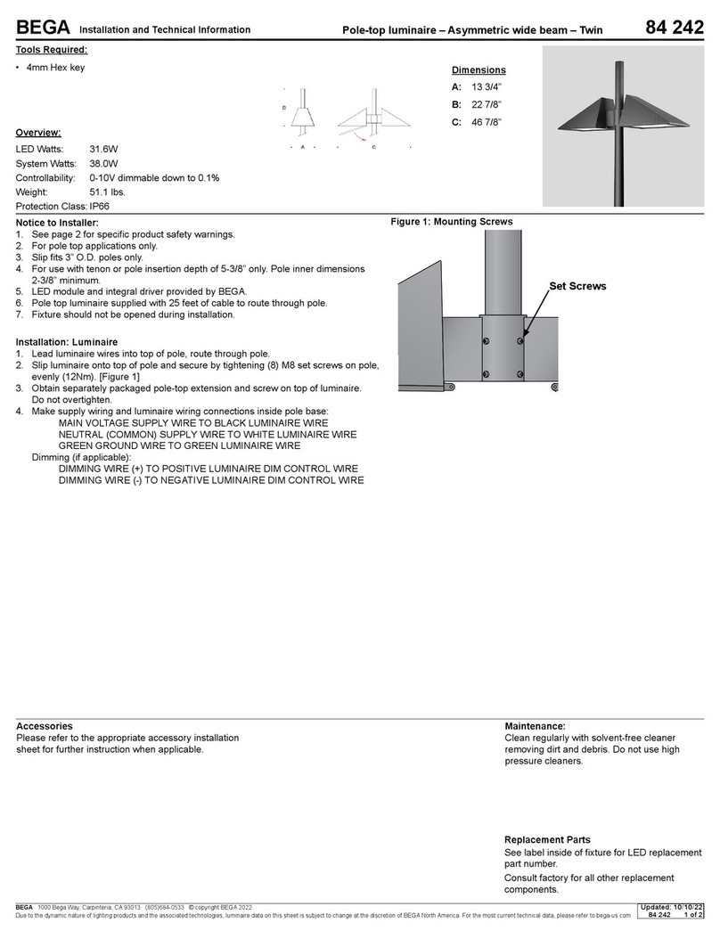
Dimensions
A: 11 3/4”
B: 7 1/8”
C: 4 1/4”
Maintenance:
Clean regularly with solvent-free cleaner
removing dirt and debris. Do not use high
pressure cleaners.
Replacement Parts
See label inside of xture for LED replacement
part number.
Consult factory for all other replacement
components.
Accessories
Please refer to the appropriate accessory installation
sheet for further instruction when applicable.
Updated: 11/30/22
24 358 1 of 2
Notice to Installer:
1. See page 2 for specic product safety warnings.
2. 4” octagonal junction box (by others) is required for installation.
3. Silicone based sealant must be used between luminaire and supporting wall
[In conformance with UL Standard 1598]
4. Do not remove the pre-installed square gasket applied to the Luminaire Backplate,
removing the gasket will void the product warranty.
5. For ceiling or wall applications only.
Installation: Luminaire
1. Open (included) mounting kit #101 and use included screws and attach mounting kit
to 4” octagonal junction box, ensure the (2) studded screws are facing away from
the wall. [Figure 1]
2. Pull supply wires and ground through the center opening on the mounting bracket.
3. On the luminaire, remove the luminaire backplate [Figure 1] by loosening the (2) set
screws at the base of luminaire body.
4. Make wiring connections inside the junction box:
MAIN VOLTAGE SUPPLY WIRE TO BLACK LUMINAIRE WIRE
NEUTRAL (COMMON) SUPPLY WIRE TO WHITE LUMINAIRE WIRE
GREEN GROUND WIRE TO GREEN LUMINAIRE WIRE
Dimming (if applicable):
DIMMING WIRE (+) TO POSITIVE LUMINAIRE DIM CONTROL WIRE
DIMMING WIRE (-) TO NEGATIVE LUMINAIRE DIM CONTROL WIRE
5. Attach the luminaire backplate onto the mounting bracket and secure using the (2)
included nuts.
6. Reinstall the luminaire body onto the backplate and secure using (2) set screws
located at the base of the luminaire body.
7. Do not remove the pre-installed square gasket applied to the luminaire backplate.
8. Apply silicone sealant between the mounting surface and the luminaire base.
-
PART NO./MMP
DESCRIPTION FROM PROGRAM
XX/XX/XXXX
REVPART NO.
SIZE
TYPE:
PROPRIETARY AND CONFIDENTIAL
THE INFORMATION CONTAINED IN THIS DRAWING IS THE SOLE PROPERTY
OF BEGA NORTH AMERICA, INC.
ANY REPRODUCTION IN PART OR AS A WHOLE WITHOUT THE WRITTEN
PERMISSION OF BEGA NORTH AMERICA, INC. IS PROHIBITED.
DATE:
APPROVED:
P (805) 684-0533 - www.bega-us.com
DESCRIPTION:
1000 BEGA Way, Carpinteria, California 93013
B
SHEET 1 OF 2
NOT TO SCALE
DATE
DESCRIPTION
CHANGED BY
REV
4” Junction Box
Mounting Kit
Luminaire Backplate
Luminaire Body


