manuals.online logo
Brands
  1. Home
  2. •
  3. Brands
  4. •
  5. BEGA
  6. •
  7. Outdoor Light
  8. •
  9. BEGA 7263LED Manual

BEGA 7263LED Manual

Installation and Technical Information
BEGA
CSA certified to U.S. and Canadian standards. Suitable
for wet locations.
In the interest of product improvement, BEGA reserves the right to make technical changes without notice.
© Copyright BEGA-US 2012
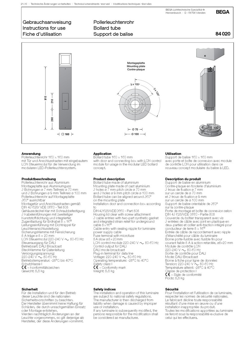
Garden bollard

0$;
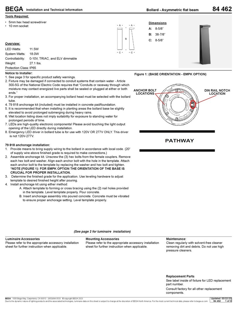
Anchorage post
Supply wiring
Bollard wiring
Set screws
Supply wiring
Luminaire 7263LED:
Housings: Garden bollard housing made of aluminum alloy with
matte safety glass. Anchorage post (supplied) made of galvanized
steel.
Electrical: 3.4W LED luminaire, 5 total system watts, -30°C start
temperature. Integral 12V AC driver provided. Standard LED color
temperature is 3000K with an 85 CRI.
Warranty: 3 year manufacturer warranty
Notice to Installer for 7263LED:
WARNING: LEDs are high-quality electrical components. Please
avoid opening upper electrical compartment and do NOT touch LED
module.
1. Compatible for use with 12-24V AC input voltage.
2. Voltage must NOT drop below 10V.
3. Turn main power OFF before start of installation.
7263LED installation:
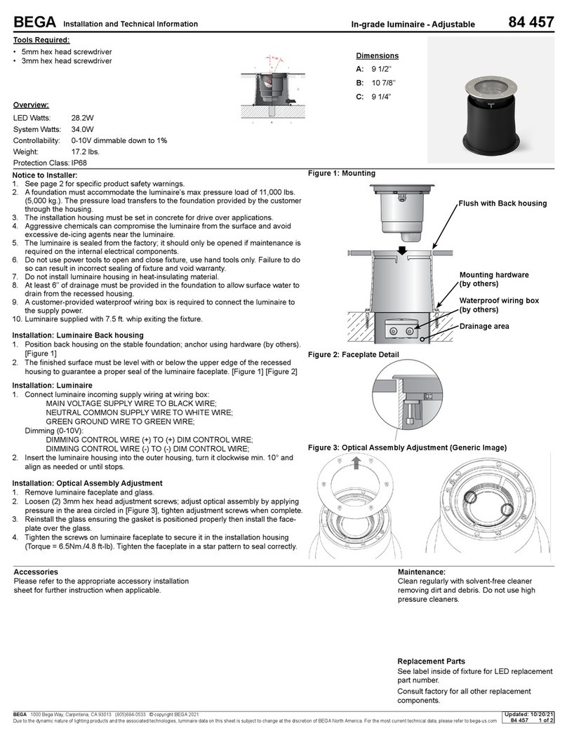
1. Establish area for fixture placement and prepare soil for
anchorage by digging a hole (12” maximum depth).
2. Dig a trench from the anchorage hole to the power source. Depth
of the trench will be determined by national, state, and local
codes.
3. Install at least 3” of pea gravel or similar in the bottom of the
anchorage hole for drainage.
4. Loosen (2) set screws on garden bollard to release anchorage
post.
5. Bring 12V-24V supply wiring into the bottom of the anchorage post
and feed through to the top until there is 12” of cable coming up
through the top of the anchorage post.
6. Bury supply wiring cable in trench.
7. Place anchorage post into hole and fill in hole with packed soil,
making sure that the post is vertical and secure.
8. Make wire splices from supply wiring coming out of anchorage
post to bollard wiring coming down from bollard shaft. For
maximum wire run lengths, see table to the right.
9. Push splices into bollard shaft.
10. Mount bollard onto anchorage post until the bottom of the
bollard hits the ground. Tighten (2) set screws to secure bollard to
anchorage shaft.
11. Connect supply wiring to main power. Turn main power on.
Garden luminaire - low voltage 7263LED
Tools Required:
3mm hex key
Standard small slotted screwdriver
Digging tool
Protection Class: IP64
Weight: 6.3 lbs.
Dimensions
A: 4 3/8”
B: 27 1/2“
Lamp: Integral 3.2W LED Module
(No replacement necessary)
7263LED
10/8/2012
18 16 14 12 10
40 46 73 116 185 294
30 61 97 155 246 392
20 92 146 232 369 588
15 122 195 309 492 784
10 183 292 464 738 1176
5 366 585 928 1477 2353
WireSize(AWG)
Max.RunLength(ft)PerWireSize:2Voltdrop
Connected
LEDWatts
Replacement Parts:
LED Module LED-0234/830
LED Driver 75946
Installation and Technical Information
BEGA
CSA certified to U.S. and Canadian standards. Suitable
for wet locations.
In the interest of product improvement, BEGA reserves the right to make technical changes without notice.
© Copyright BEGA-US 2012
Garden bollard
Anchor bolts
(by others)
Supply wiring
Bollard wiring
Set screws
Anchor base
Supply wiring
Anchor base flange
Luminaire 7264LED:
Housings: Garden bollard housing made of aluminum alloy with
matte safety glass. Anchorage base made of hot-dip galvanized steel,
made for bolting onto foundation (by others) or other paved surfaces.
Electrical: 3.4W LED luminaire, 5 total system watts, -30°C start
temperature. Integral 12V AC driver provided. Standard LED color
temperature is 3000K with an 85 CRI.
Warranty: 3 year manufacturer warranty
Notice to Installer for 7264LED:
WARNING: LEDs are high-quality electrical components. Please
avoid opening upper electrical compartment and do NOT touch LED
module.
1. Compatible for use with 12-24V AC input voltage.
2. Voltage must NOT drop below 10V.
3. Turn main power OFF before start of installation.
4. Anchorage hardware provided by others.
7264LED installation:
1. Loosen (2) set screws on garden bollard to remove anchor
base and anchor base flange.
2. Bring 12V-24V supply wiring into the bottom of the anchor base
and feed through to the top until there is 12” of cable coming up
through the top of the anchor base.
3. Fix anchor base to existing foundation or surface using sufficient
anchor hardware, supplied by others.
4. Slide anchor base flange over anchor base so it covers the anchor
bolts.
5. Make wire splices from supply wiring coming out of anchor
base to bollard wiring coming down from bollard shaft. For
maximum wire run lengths, see table to the right.
6. Push splices into bollard shaft.
7. Mount bollard onto anchor base until the bottom of the
bollard hits the anchor base flange. Tighten (2) set screws to
secure bollard to anchorage shaft.
8. Connect supply wiring to main power. Turn main power on.
Garden luminaire - low voltage 7264LED
Tools Required:
3mm hex key
Standard small slotted screwdriver
Digging tool
Protection Class: IP64
Weight: 5.3 lbs.
Dimensions
A: 4 3/8”
B: 27 1/2“
Lamp: Integral 3.4W LED Module
(No replacement necessary)
7264LED
10/8/2012
18 16 14 12 10
40 46 73 116 185 294
30 61 97 155 246 392
20 92 146 232 369 588
15 122 195 309 492 784
10 183 292 464 738 1176
5 366 585 928 1477 2353
WireSize(AWG)
Max.RunLength(ft)PerWireSize:2Voltdrop
Connected
LEDWatts
Replacement Parts:
LED Module LED-0234/830
LED Driver 75946

Other BEGA Outdoor Light manuals

BEGA 84 242 Manual

BEGA

BEGA 84 242 Manual

BEGA 33 592 User manual

BEGA

BEGA 33 592 User manual

BEGA 67 541.3 Series User manual

BEGA

BEGA 67 541.3 Series User manual

BEGA 84 121 User manual

BEGA

BEGA 84 121 User manual

BEGA 24 216 Manual

BEGA

BEGA 24 216 Manual

BEGA 71 601 User manual

BEGA

BEGA 71 601 User manual

BEGA 24 102 Manual

BEGA

BEGA 24 102 Manual

BEGA 77 146 User manual

BEGA

BEGA 77 146 User manual

BEGA 84 699 User manual

BEGA

BEGA 84 699 User manual

BEGA 71 128 Manual

BEGA

BEGA 71 128 Manual

BEGA 7723 User manual

BEGA

BEGA 7723 User manual

BEGA 33 242 User manual

BEGA

BEGA 33 242 User manual

BEGA 24 353 Manual

BEGA

BEGA 24 353 Manual

BEGA 85 046 User manual

BEGA

BEGA 85 046 User manual

BEGA 84 667 User manual

BEGA

BEGA 84 667 User manual

BEGA 24 358 Manual

BEGA

BEGA 24 358 Manual

BEGA 84 326 User manual

BEGA

BEGA 84 326 User manual

BEGA 22 327 User manual

BEGA

BEGA 22 327 User manual

BEGA 88 619 User manual

BEGA

BEGA 88 619 User manual

BEGA 24 013 Manual

BEGA

BEGA 24 013 Manual

BEGA 84 724 User manual

BEGA

BEGA 84 724 User manual

BEGA 33 539 Manual

BEGA

BEGA 33 539 Manual

BEGA 84 128 Manual

BEGA

BEGA 84 128 Manual

BEGA 77 138 User manual

BEGA

BEGA 77 138 User manual

Popular Outdoor Light manuals by other brands

Allen + Roth RDY1740-01-ORB manual

Allen + Roth

Allen + Roth RDY1740-01-ORB manual

marset Lab 35/60 B Assembly instructions

marset

marset Lab 35/60 B Assembly instructions

LIGMAN ROBUST 1 installation manual

LIGMAN

LIGMAN ROBUST 1 installation manual

Catalina 20745-000 manual

Catalina

Catalina 20745-000 manual

LIGMAN VK-30001 installation manual

LIGMAN

LIGMAN VK-30001 installation manual

Philips Ecomoods 16900/93/16 Specification sheet

Philips

Philips Ecomoods 16900/93/16 Specification sheet

Tala Echo Sphere installation guide

Tala

Tala Echo Sphere installation guide

STERNO HOME U000-5048 instructions

STERNO HOME

STERNO HOME U000-5048 instructions

LIGMAN FORREY 5 installation manual

LIGMAN

LIGMAN FORREY 5 installation manual

Trio KAVERI manual

Trio

Trio KAVERI manual

LUCIDE LIVIA 11812/01/30 General Specifications

LUCIDE

LUCIDE LIVIA 11812/01/30 General Specifications

VIBIA Suite Assembly instructions

VIBIA

VIBIA Suite Assembly instructions

oluce SUPERLUNA 397 Mounting instructions

oluce

oluce SUPERLUNA 397 Mounting instructions

Eiko Trapezoid installation instructions

Eiko

Eiko Trapezoid installation instructions

Harris ALLED3 Series installation guide

Harris

Harris ALLED3 Series installation guide

PEWA STEINEL L 320 wave installation instructions

PEWA

PEWA STEINEL L 320 wave installation instructions

Addington Park 30812125 instructions

Addington Park

Addington Park 30812125 instructions

Lighting Technologies NTV 130 E40 ball opal 200 manual

Lighting Technologies

Lighting Technologies NTV 130 E40 ball opal 200 manual

manuals.online logo
manuals.online logoBrands
  • About & Mission
  • Contact us
  • Privacy Policy
  • Terms and Conditions

Copyright 2025 Manuals.Online. All Rights Reserved.