4
1.2.4 Clock
When programmed as a digital clock the BA364D
will display local time within a hazardous area.
The two optional solid state outputs may be
programmed to turn on and off twice during each
24 hour period.
See section 5 of this manual for a detailed
description of the clock functions.
1.3 INITIALISATION
Each time power is applied to the BA364D
initialisation is performed. After a short delay the
following display sequence occurs:
All segments of the display are activated
for about 2 seconds.
The product firmware and versionnumber
are shown on the top display and the
current instrument function i.e. Countr,
ELAPSE, tACHO or CLOC are displayed
on the lower display for 2 seconds.
The BA364D starts to function using the
calibration information stored in the
permanent memory.
1.4 INTRINSIC SAFETY CERTIFICATION
1.4.1 ATEX certification
The BA364D has been issued with EC-Type
Examination Certificate number ITS01ATEX2003
by Notified Body Intertek Testing Services (ITS)
confirming compliance with the European ATEX
Directive 94/9/EC for Group II, Category 1, gas
and dust atmospheres, EEx ia IIC T5. The
instrument bears the Community Mark and
subject to local codes of practice, may be
installed in any of the European Economic Area
(EEA) member countries. ATEX certificates are
also acceptable for installations in Switzerland.
This manual describes installations in explosive
gas atmospheres which conform with BS
EN60079:Part14:2003 Electrical Installation in
Hazardous Areas. When designing systems for
installation outside the UK, the local Code of
Practice should be consulted.
For use in the presence of combustible dust,
please refer to Appendix 1 which describes
installations complying with BS EN 50281-1-
2:1999.
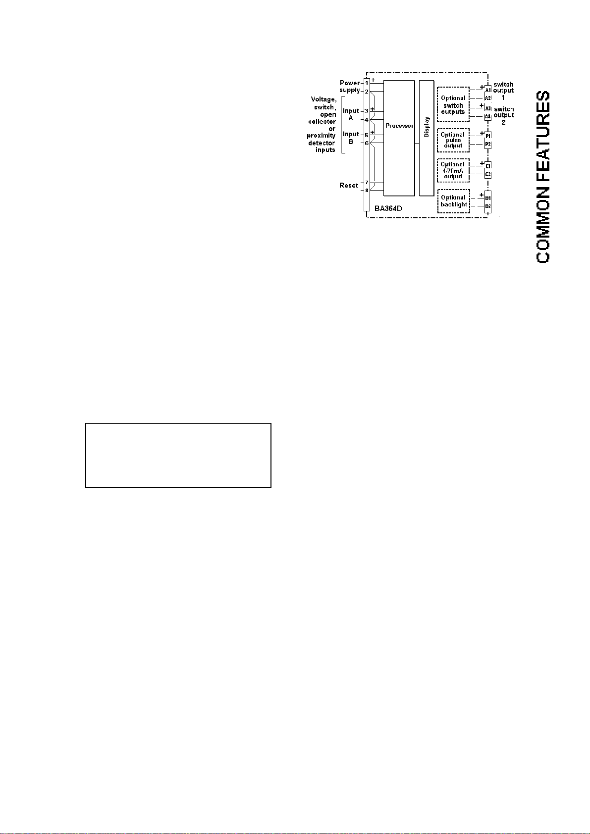
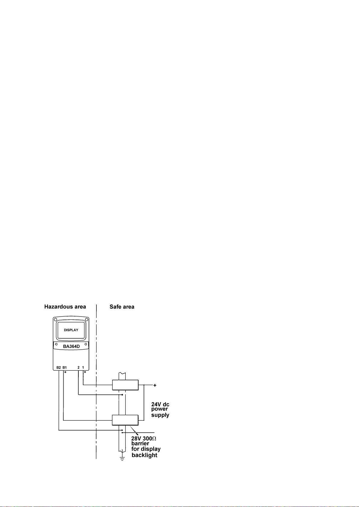
1.4.2 Power supply
When installed in a hazardous area the BA364D
must be powered via a Zener barrier or galvanic
isolator from a dc supply located in the safe area.
The input safety parameters for terminals 1 and 2
are: Ui = 28V dc
Ii = 100mA dc
Pi = 0.7W
Any certified Zener barrier or galvanic isolator
with output safety parameters within these limits
may be used. Two system certificates provide
guidance to help selection of suitable devices.
The maximum equivalent capacitance and
inductance between terminals 1 and 2 is:
Ci = 20nF
Li = 20 H
When installing a system not covered by the
BA364D system certificates, these figures must
be subtracted from the maximum cable
parameters for the certified device powering the
BA364D.
1.4.3 Pulse input terminals
The BA364D has two identical inputs designated
A (terminals 3 & 4) and B (terminals 5 & 6).
Each may be connected to a voltage pulse,
switch, open collector or certified intrinsically safe
2-wire proximity detector. The safety parameters
of each input are:
Ui = 28V dc
Ii = 100mA dc
Pi = 0.7W
Uo = 10.5V dc
Io = 9.2mA dc
Po = 24mW
Note: when programmed as a tachometer only
one input may be used and when programmed
as a clock neither of the inputs are available.
Hazardous area mechanically operated switches
comply with the requirements for simple
apparatus and may be directly connected to
either input. Similarly, optically isolated open
collector outputs that comply with the
requirements for simple apparatus may also be
directly connected to either input.
The BA364D system certificates specify some of
the intrinsically safe 2-wire proximity detectors
that may be connected directly to the two
instrument inputs. Other certified intrinsically
safe detectors may be used providing their input
safety parameters less than the BA364D output
parameters.