BEKA BA568E User manual

Issue: 5
25th July 2019
BA568E
Two Input
General purpose
Counter
Issue 5

1. Description
2. Operation
2.1 Initialisation
2.2 Controls
2.3 Displays
3. System Design
3.1 Power supply
3.2 Pulse input
3.2.1 Switch contact input
3.2.2 2-wire proximity detector input
3.2.3 Open collector
3.2.4 Magnetic pick-off input
3.2.5 Voltage pulse input
3.3 Remote reset
4. Installation
4.1 Location
4.2 EMC
4.3 Installation procedure
4.4 Scale card
5. Configuration and Calibration
5.1 Calibration structure
5.2 Accessing configuration functions
5.3 Summary of configuration functions
5.4 Input A
5.5 Input A type
5.6 Input A debounce
5.7 Input b
5.8 Input b type
5.9 Input b debounce
5.10 Input A pulse counting edge
5.11 Input b pulse counting edge
5.12 Display update interval
5.13 Counting function
5.14 Upper display
5.15 Lower display
5.16 Position of decimal points
5.17 Total scale factor
5.18 Rate scale factor
5.19 Timebase
5.20 Display filter
5.21 Direction of count
5.22 Reset value
5.23 Local reset
5.24 Local total reset
5.25 Local grand total reset
5.26 Reset grand total from configuration
menu.
5.27 Security code
5.28 Reset configuration to factory defaults
5.29 Display overflow
6. Pulse Output
6.1 System design
6.2 Configuration
6.3 Access pulse output sub-menu
6.4 Enable pulse output
6.5 Source of output pulse
6.6 Divide output pulse frequency
6.7 Output pulse width
7. Configuration example
8. Maintenance
8.1 Fault finding during commissioning
8.2 Fault finding after commissioning
8.3 Servicing
8.4 Routine maintenance
8.5 Guarantee
8.6 Customer comments
9. Accessories
9.1 Scale card
9.2 Tag information
9.3 Alarms
9.3.1 Solid state output
9.3.2 Summary of configuration
functions.
9.3.3 Alarm enable
9.3.4 Type of alarm
9.3.5 Setpoint adjustment
9.3.6 Alarm function
9.3.7 Alarm output status
9.3.8 Hysteresis
9.3.9 Alarm delay
9.3.10 Alarm silence time
9.3.11 Flash display when alarm
occurs.
9.3.12 Access setpoint
9.3.13 Adjusting alarm setpoints
from display mode.
9.4 Display backlight
9.5 4/20mA output
9.5.1 System design
9.5.2 Configuration and calibration
9.5.3 Access 4/20mA output sub-menu
9.5.4 Enable 4/20mA output
9.5.5 Select rate or total source
9.5.6 Define display for 4mA output
9.5.7 Define display for 20mA output
2222222222222222222222222
CONTENTS
The B
A
568E is CE marked to show com
p
liancewiththeEuro
p
ean EMC Directive 2014/30
/
EU

1. DESCRIPTION
This general purpose, two input pulse counter will
accept pulses on one or both inputs and may be
configured to show one of the following in
engineering units on an eight digit display:
Input A + Input b
Input A - Input b
Input A direction controlled by Input b
Quadrature input
(Input A and Input b electrically 90oapart)
A smaller six digit display may be activated to show
the composite pulse rate in engineering units per
second, minute or per hour.
In addition to simple counting applications, the
quadrature input allows direction of movement and
position to be displayed.
The optically-isolated pulse output may be
configured to synchronously retransmit either of the
two inputs or a scaled composite output.
This instruction manual supplements the abbreviated
instruction sheet supplied with each instrument.
2. OPERATION
Fig 1 shows a simplified block diagram of the
BA568E Counter. The instrument has two inputs, A
and b, which can be configured to accept pulses
from most types of sensor and display the total
number of pulses received and their combined rate
on separate displays.
Each input can be individually configured to accept
pulses from a wide variety of sensors. When the
sensor requires energising to determine its status,
such as a switch contact, open collector or a two
wire proximity detector, an external link supplies
power to the input terminals.
The BA568E may be supplied with any of the
following factory fitted accessories:
Internally powered display backlight
Dual isolated alarms
Isolated 4/20mA output
Fig 1 BA568E block diagram
2.1 Initialisation
Each time power is applied to a BA568E Counter
initialisation is performed. After a short delay the
following display sequence occurs:
All segments of the display are activated
The Counter starts functioning using the
configuration information stored in the
instrument’s permanent memory. Unless total
and grand total displays have been reset to
zero, new pulses will be added to the existing
totals.
3

2.2 Controls
The BA568E Counter is controlled and configured
via four front panel push buttons. In the display
mode i.e. when the instrument is counting the push
button functions are:
Push Button Functions
) + &Grand total - shows Lo followed by least
significant 8 digits of the 16 digit grand
total.
) + * Grand total - shows Hi followed by the
most significant 8 digits of the 16 digit
grand total.
If Local Grand Total Reset CLr Gtot in
the instrument configuration menu has
been activated, operating the ) and
*buttons simultaneously for ten
seconds will result in Clr .no being
displayed with the no flashing.
Operating the *or &button will
change the display to Clr .YE5, the )
button will then reset the grand total to
zero which will be confirmed by a brief
display of Gt Clrd. See 6.25
& + *If Local Total Reset CLr tot in the
instrument configuration menu has
been activated, operating the & and
*buttons simultaneously for three
seconds will reset the total display to
zero and clear any pulses stored in the
optional pulse output.
See 5.24
(+ &Shows firmware version
( + )Access to configuration menu
Note: When optional alarms are fitted, the BA568E
Counter may be configured to provide direct access
to the alarm setpoints from the display mode when
the (and *buttons are operated simultaneously.
See 9.3.12 and 9.3.13
2.3 Displays
The BA568E Counter has two digital displays and
associated annunciators, plus a pulse input indicator
as shown on the front cover of this manual.
Total Shows the total pulse count on the
display upper eight digit display. May be
reset to zero via front panel push
buttons or by a remote reset switch.
Rate Shows the pulse rate on the lower six
Display digit display. Total and rate displays
may be reversed.
Pulse input This disc in the lower left hand corner
indicator of the display 'rotates' for two
seconds each time an input pulse is
received on either input. Appears to
rotate continuously when combined
input frequency on both inputs
exceeds 0.5Hz.
Reset Activated while the total display
annunciator is being reset via the front panel
push buttons, or the external reset
terminals.
Rate Identifies rate display
annunciator
Total Identifies total display
annunciator
RTx Retransmitted pulse
annunciator annunciator.
Depends upon the setting of 5ource
in the pulse output configuration
menu.
5caled:
Annunciator activated each time
pulse output open collector is on,
i.e. Ron is less than 60+ 3V.
direct:
Annunciator continuously
activated.
4

3. SYSTEM DESIGN
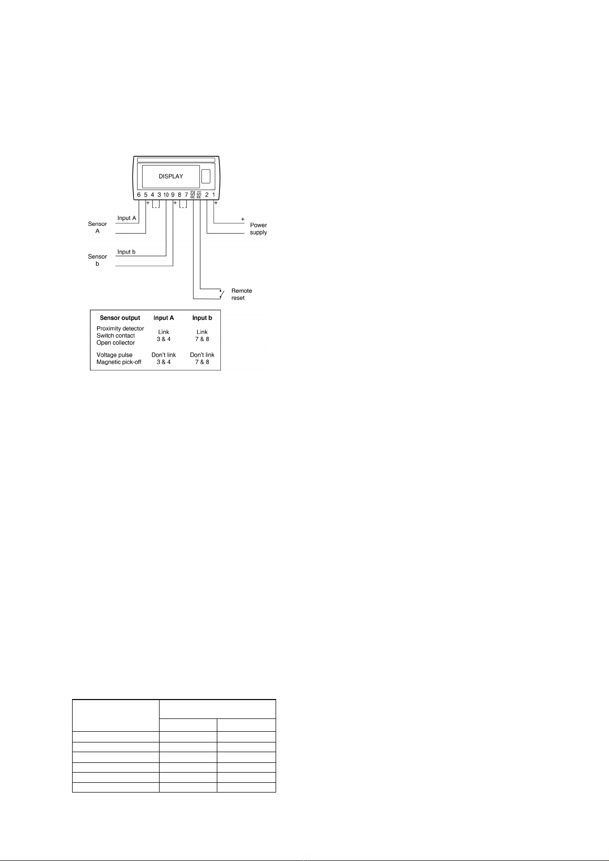
Fig 2 illustrates the basic circuit that is used for all
BA568E Counter installations. For simplicity,
connections for the pulse output and the optional
alarms and 4/20mA output are shown separately in
sections 6 and 9 of this manual.
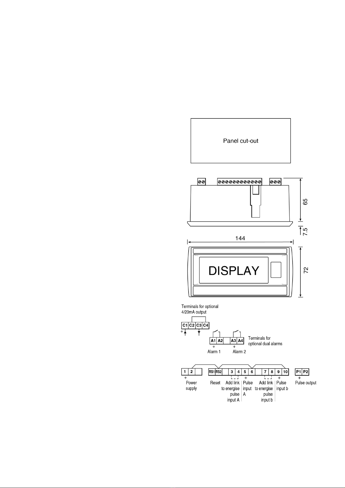
Fig 2 BA568E connections
When designing a system it is important to
remember that terminals 2, 6, 10 and RS2 are
interconnected within the BA568E See Fig 1.
3.1 Power supply
The BA568E Counter requires a 10 to 30V dc supply
between terminal 1 & 2 and consumes:
10mA
plus 16mA for optional backlight
plus 6mA when terminals 3 & 4 are linked
plus 6mA when terminals 7 & 8 are linked
______
38mA
3.2 Pulse input
As shown in Fig 2 the BA568E can count pulses
from a wide variety of sensors.
The following table shows the switching thresholds
for the various types of sensor. For reliable
counting the pulse input must fall below the lower
threshold and rise above the upper threshold.
Input sensor
Switching thresholds
Lower Upper
Switch 1001000
Proximity detector 1.2mA 2.1mA
Open collector 2k10k
Magnetic pick-off 0 40mV peak
Voltage pulse low 1.0V 3.0V
Voltage pulse high 3.0V 10.0V
3.2.1 Switch contact input
Any switch contact may be directly connected to the
pulse input terminals 5 & 6 and 9 & 10. Each input
of the BA568E contains a configurable debounce
circuit to prevent contact bounce being counted.
See section 5.6 including details of the maximum
counting frequency.
3.2.2 2-wire proximity detector input
Most NAMUR 2-wire proximity detector may be
connected directly to the BA568E pulse inputs,
providing the minimum operating voltage of the
proximity detector is less than 7.5V. Each input of
the BA568E contains a configurable debounce
circuit to prevent contact bounce being counted.
See section 5.6 including details of the maximum
counting frequency.
3.2.3 Open collector input
Sensors with an open collector output may be
directly connected to Counter input terminals 5 & 6
and 9 & 10. Polarity of the sensor output should be
observed. Each input of the BA568E contains a
configurable debounce circuit to prevent contact
bounce being counted. See section 5.6 including
details of the maximum counting frequency.
3.2.4 Magnetic pick-off input
Sensors incorporating a magnetic pick-off will have a
low level voltage output unless the sensor
incorporates an amplifier. CoiL in the BA568E input
configuration menu is a low level voltage pulse input
intended for use with a magnetic pick-off. Each
input of the BA568E contains a configurable
debounce circuit to prevent contact bounce being
counted. See section 5.6 including details of the
maximum counting frequency.
3.2.5 Voltage pulse input
Two voltage pulse input ranges are selectable in the
BA568E Counter configuration menu, VoLt5 L and
VoLt5 H as shown in section 3.2. Each input of the
BA568E contains a configurable debounce circuit to
prevent contact bounce being counted. See section
5.6 including details of the maximum counting
frequency.
3.3 Remote reset
The Counter's total display may be remotely reset
by connecting terminals RS1 and RS2 together for
more than one second. Permanent interconnection
inhibits counting.
Note: The BA568E may also be configured to
reset the total display by operating the &
and *push buttons simultaneously for
more than two seconds in the counting
mode. See 5.24
5

4. INSTALLATION
4.1 Location
The BA568E Counter has a robust glass reinforced
Noryl enclosure with a toughened glass window.
The front of the instrument has IP66 ingress
protection and a gasket seals the joint between the
instrument enclosure and the panel. The rear of the
instrument has IP20 ingress protection.
The BA568E may be installed in any panel providing
that the operating temperature is between -40°C and
+70°C. At temperatures below -20°C the instrument
will continue to count but the display digits will
change more slowly and the display contrast will be
reduced.
Figs 3 shows the overall dimensions together with
the recommended panel cut-out dimensions. To
achieve an IP66 seal between the instrument
enclosure and the instrument panel, the smaller cut-
out dimensions should be used and the instrument
should be secured with four panel mounting clamps.
4.2 EMC
The BA568E Counter complies with the
requirements of the European EMC Directive
2014/30/EU. For specified immunity all wiring
should be in screened twisted pairs, with the screens
earthed at one point.
Recommended panel cut-out
dimensions for all installations
Mandatory to achieve an IP66 seal
between instrument and panel
136 +0.5/-0.0 x 66.2 +0.5/-0.0
DIN 43700
138.0 +1.0/ -0.0 x 68 +0.7 -0.0
Note: Optional backlight is internally powered
Fig 3 BA568E dimensions & terminals
6

4.3 Installation Procedure
a. Cut the specified aperture in the panel. To
achieve an IP66 seal between the instrument
enclosure and the instrument panel the
aperture must have the tighter tolerances
specified in Fig 3.
b. Slide the gasket over the body of the BA568E
Counter before inserting the instrument into
the panel aperture.
c. Firstly ensure that all the panel mounting
clamps are closed by turning the knurled
screws fully anti clockwise until the two pips in
the clamp foot align with holes in the clamp
body.
d. Place a clamp in the recess on each side of
the Counter, pulling gently to slide it onto the
dovetail as shown in Fig 4. Push the knurled
screw slightly forward to engage the thread
and tighten by turning clockwise until it is just
finger tight. When all clamps are fitted ensure
that the gasket behind the front panel bezel is
correctly positioned before fully tightening the
clamps to secure the instrument. The
maximum recommended clamp tightening
torque is 22cNm (1.95 lbf in) which is
approximately equivalent to finger-tight plus
one half turn. Do not over tighten.
e. Four panel mounting clamps are required to
achieve an IP66 seal between a BA568E
Counter and the instrument panel.
f. Connect the panel wiring to the rear terminal
block(s) as shown in Fig 3. To simplify
installation, the terminals are removable so
that the panel wiring can be completed before
the instrument is installed. To prevent
vibration damage ensure panel wiring is
supported.
Fig 4 Fitting panel mounting clamps
4.4 Scale card
The Counter’s units of measurement may be shown
on a printed scale card in a window at the right hand
side of the display. The scale card is mounted on a
flexible strip that is inserted into a slot at the rear of
the instrument as shown in Fig 5. Thus the scale
card can easily be changed without removing the
Counter from the panel or opening the instrument
enclosure.
New BA568E Counters are supplied with a printed
scale card showing the requested units of
measurement, if this information is not supplied
when the instrument is ordered a blank card will be
fitted.
A pack of self-adhesive scale cards printed with
common units is available as an accessory from
BEKA associates. Custom printed scale cards can
also be supplied.
To change a scale card, unclip the tapered end of
the flexible strip at the rear of the instrument by
gently pushing it upwards and pulling it out of the
enclosure. Peel the existing scale card from the
flexible strip and replace it with a new printed card,
which should be aligned as shown below. Do not fit
a new scale card on top of an existing card.
Install the new scale card by gently pushing the
flexible strip into the slot at the rear of the Counter,
when it reaches the internal end-stop secure it by
pushing the end of the flexible strip downwards so
that the tapered section is held by the rear panel.
Align the self-adhesive printed
scale card onto the flexible strip
and insert the strip into the
Counter as shown below.
Fig 5 Inserting the flexible strip carrying the scale
card into slot at the rear of the BA568E Counter.
7

5.0 CONFIGURATION & CALIBRATION
The BA568E Counter is configured and calibrated
via four front panel push buttons. All the
configuration functions are contained in an easy to
use intuitive menu that is shown diagrammatically in
Fig 7.
Each menu function is summarised in section 5.3 of
this manual and each summary includes a reference
to more detailed information.
The isolated pulse output, including configuration, is
described in section 6 of this manual. When factory
fitted optional alarms and the optional 4/20mA output
are included, additional functions appear in the
configuration menu which are described in section 9
of this manual.
All new BA568E Counters are supplied calibrated as
requested at the time of ordering. If calibration is not
requested, Counters will have default configuration
as shown in the following table, but can easily be re-
configured on-site.
Function Display Default
Input A inP .tYPE oP .CoL
Debounce dEbounCE dEFAuLt
Input b inP .tYPE oP .CoL
Debounce dEbounCE dEFAuLt
Counting edge A CntEdG-A EdGE 1
Counting edge b CntEdG-b EdGE 1
Update uPdAtE 0.5
Count Count A:b
Upper display di5p-1 totAL
Lower display di5P-2 on
Decimal point dP Rate 00000 .0
Total 00000000
Total scale factor 5CALE .t001.00
Rate scale factor 5CALE .r001.00
Timebase t-bA5E tb-01
Filter FiLter 24
Counter direction uP or dn uP
Clear value clr val 00000000
Local clear loc clr
Local total reset Clr tot oFF
Local grand total reset Clr Gtot oFF
Security code CodE 0000
Note: While the instrument is being configured
counting continues so that any input pulses
occurring during this time are recorded.
5.1 Calibration structure
Fig 6 shows the calibration structure of the BA568E
Counter. The two pulse inputs are processed by the
count function to produce a single output having the
selected arithmetic function, such as the sum of
pulse input A and pulse input b. This output is
passed to the 5cALE .rand 5CALE .T functions
allowing the rate and total displays to have different
engineering units.
5CALE .tis a dividing factor that converts the output
from the Counter function into the required total
display in engineering units. e.g. if the output from
the Counter function is two pulses per pump stroke
and a total display of thousands of pump strokes is
required, 5CALE .tshould be set to 2000.
5CALE .ris a dividing factor that converts the output
from the Counter function into a rate display with the
required engineering units. e.g. if the output from
the Counter function is two pulses per pump stroke
and it is required to display the pump stroke rate,
5CALE .rshould be set to 2.
The timebase t-bA5E is a multiplying factor that
determines if the instrument displays rate per
second, per minute or per hour.
The BA568E uses ‘real’ decimal points. Moving the
position of a decimal point in a scale factor will affect
the instrument calibration.
Fig 6 Calibration structure
8

5.2 Accessing configuration functions
Throughout this manual the instrument front panel
push buttons are shown as &, *, (and )and
legends displayed by the instrument are shown in a
seven segment font as displayed by the Counter
e.g. FiLtEr and 5CALE .r.
Access to the configuration menu is obtained by
operating the (and )push buttons
simultaneously. If the instrument is not protected by
a security code the first parameter inPut-A will be
displayed. If a security code other than the default
code 0000 has already been entered, the instrument
will display CodE. Press (to clear this prompt and
enter the security code for the instrument using the
&or *push button to adjust the flashing digit,
and the (push button to transfer control to the
next digit. If the correct code has been entered
pressing )will cause the first parameter inPut-A
to be displayed. If an incorrect code is entered, or a
push button is not operated within ten seconds, the
instrument will automatically return to the display
mode.
All configuration functions and prompts are shown
on the upper eight digit display.
Once within the configuration menu the required
function can be selected by scrolling through the
menu using the &and *push buttons. The
configuration menu is shown diagrammatically in
Fig 7.
When returning to the display mode following
reconfiguration, the BA568E Counter will display
dAtA followed by 5AVE while the new information is
stored in permanent memory.
If after accessing the configuration menu the interval
between operating any front panel push button
exceeds one minute, the BA568E will automatically
return to the display mode and any configuration
changes will not be stored in permanent memory.
When making changes to multiple configuration
functions, it is therefore sensible to occasionally
return to the display mode to save the changes that
have already been made.
5.3 Summary of configuration functions
This section summarises all the configuration
functions. When read in conjunction with Fig 7 it
provides a quick aid for configuring the Counter. If
more detail is required, each summary contains a
reference to a full description of the function.
Display Summary of function
inPut-A Contains sub-menu with two
functions:
inP .tYPE Select Input type
dEbounCE Set debounce
See section 5.4
inP .tYPE [for Input-A]
Configures input-A to accept one of
six types of input:
oP .CoL Open collector *
VoLt5 L Voltage pulse <1 >3V
VoLt5 H Voltage pulse <3 >10V
CoiL Magnetic pick-off
Pr .dEt Proximity detector *
ContACt Switch contact *
*Link terminals 3 & 4
See section 5.5
dEbounCE [[[for Input-A]
Defines level of input debounce
applied to the pulse input A to
prevent false counting:
dEFAuLt
HEAVY
LiGHt
See section 5.6
inPut-b Contains sub-menu with two
functions:
inP .tYPE Select Input type
dEbounCE Set debounce
See section 5.7
inP .tYPE [for Input-b]
Configures input-b to accept one of
six types of input:
oP .CoL Open collector *
VoLt5 L Voltage pulse <1 >3V
VoLt5 H Voltage pulse <3 >10V
CoiL Magnetic pick-off
Pr .dEt Proximity detector *
ContACt Switch contact *
*Link terminals 7 & 8
See section 5.8
9

Display Summary of function
dEbounCE [for Input-b]
Defines level of input debounce
applied to the pulse input b to
prevent false counting:
dEFAuLt
HEAVY
LiGHt
See section 5.9
CntEdG-A Input A pulse counting edge
Defines whether the Counter is
incremented/decremented on the
leading or trailing edge of a pulse on
input A.
See section 5.10
CntEdG-b Input b pulse counting edge
Defines whether the Counter is
incremented/decremented on the
leading or trailing edge of a pulse on
input b.
See section 5.11
updAtE Display update interval
Defines the interval between display
updates between 0.5 and 5
seconds.
See section 5.12
Count Counting function
Defines the arithmetic relationship of
the two pulse inputs. The total
display can be derived from:
A:bInput A + Input b
A:-b Input A - Input b
A con b Input A controlled by
Input b.
a rel b Quadrature input
(for position display)
See section 5.13
di5P-1 Upper display
Defines whether rAtE or totAL is
shown on the upper display. The
other variable will be shown on the
lower display, providing the lower
display is on in function dI5P-2.
See section 5.14
Display Summary of function
di5P-2 Lower display
Turns the lower display, which
normally shows rate, on or oFF.
See section 5.15
dP Position of decimal points
Defines the position of the decimal
point in both the total and rate
displays.
See section 5.16
5CALE .tTotal Scale Factor
5CALE .tis a dividing factor that
converts the pulse output from
arithmetic Count function into the
required total display in engineering
units. 5CALE .tmay be adjusted
between. 0.0001 and 99999. e.g. if
one pulse represents 1 centimetre of
dispensed cable and the total
display is required in metres,
5CALE .tshould be set to 100.0
which is the number of centimetres
in a metre.
The total display is independent of
the rate display.
See section 5.17
5CALE .rRate scale factor
5CALE .ris a dividing factor that
converts the pulse output from the
arithmetic Count function into the
required rate display in engineering
units. 5CALE .rmay be adjusted
between 0.0001 and 99999. e.g. if
one pulse represents 2 pump
strokes and the rate display is
required in pump strokes, 5CALE .r
should be set to 0.5.
The rate display is independent of
the total display.
See section 5.18
t-bA5E Timebase
Selectable multiplier allowing rate to
be displayed in units per second, per
minute or per hour.
Select:
tb-01 for rate / second
tb-60 for rate / minute
tb-3600 for rate / hour
See section 5.19
10

Display Summary of function
FiLtEr Display filter
Is an adjustable digital filter to
reduce the noise on the rate display.
The filter has two parameters each
represented by a digit adjustable
between 0 and 9. The first digit
defines the amount of filtering
applied to the display, the second
digit the deviation from the displayed
rate at which the filter will be
overridden and the rate display will
move rapidly to the new value.
See section 5.20
&or *Direction of count
Determines whether pulses at inputs
A and b increment or decrement the
total display.
See section 5.21
CLr VAL Reset value
Defines a preset number to which
the total display will be set when the
BA568E Counter is locally or
remotely reset. Enables the
instrument to count down from a
preset number.
See section 5.22
LoC CLr Local clear
Contains sub-menu with two
functions enabling the total and the
grand total to be reset via the front
panel push buttons while the
Counter is in the display mode.
See section 5.23
Clr tot
When on is selected total display is
reset when &and *buttons are
operated simultaneously for more
than 3 seconds in the display mode.
See section 5.24
Clr Gtot
When on is selected the grand total
may be reset when )and *
buttons are operated simultaneously
for more than 10 seconds in the
display mode - see section 2.2 for
details.
Note: Once reset, the grand total
can not be restored.
See section 5.25
Display Summary of function
Clr Gtot Resets grand total to zero from
within configuration menu.
This function resets the grand total
to zero from within the configuration
menu when CLr YE5 is selected.
Note: Once reset, the grand total
can not be recovered.
See section 5.26
CodE Access code
Defines a four digit alphanumeric
code that must be entered to gain
access to the configuration menu.
Default code 0000 disables the
security function and allows
unrestricted access to all
configuration functions.
See section 5.27
r5Et dEF Reset to factory defaults
Returns the BA568E Counter to the
factory defaults shown in section 5.0
To prevent accidental use the
request must be confirmed by
entering 5urE before the reset will
be executed.
See section 5.28
11

12

13

5.4 Input A: inPut-A
The Input A function contains two sub-functions
inP .tYPE and dEbounCE that define the type of input
and the amount of input noise rejection.
5.5 Input A type: inP.tYPE
inP .tYPE is a sub-menu in the inPut-A function
which defines the type of input sensor or input pulse
that the instrument will count at Input-A. To check or
change the type of input, select inPut-A in the
configuration menu and press (which will reveal
the inP.tYPE prompt, pressing (again will show
the existing Input-A setting. If set as required press
)twice to return to the configuration menu, or
repeatedly press the &or *button until the
required type of input is displayed and then press
)twice to return to the configuration menu.
One of following six types of input may be selected:
Switching
thresholds
Low High
oP .CoL Open collector 2210k
VoLt5L Voltage pulse low 113V
VoLt5H Voltage pulse high1310V
CoiL Magnetic pick-off 0 40mV
Pr .dEt Proximity detector 21.2 2.1mA
ContACt Switch contact 2100 1000
Notes:
1. Maximum voltage input +30V.
2. For sensors connected to Input-A that require
energising i.e. proximity detectors, switch
contacts or open collector sensors, terminals
3 & 4 of the BA568E should be linked
together.
3. To count correctly, the input pulse must fall
below the lower switching threshold and rise
above the higher switching threshold.
4. See section 5.6 for maximum counting
frequency.
5.6 Input A debounce: dEbouncE
dEbouncE is an adjustable sub-menu in both the
inPut-A and inPut-b functions which prevents the
input miscounting when the input pulse has noisy
edges, such as those resulting from a mechanical
contact closing and bouncing. The debounce
function only applies to the input in which the
function is located.
Three levels of protection may be independently
selected for each input. The amount of debounce
applied depends upon the type of Counter input that
has been selected for the input in the associated inP
.tYPE function.
Select inPut-A or inPut-b in the configuration menu
and press (which will reveal the inP .tYPE prompt,
press the &or *button to select dEbouncE
followed by (to reveal the existing setting.
Pressing the &or *button will scroll through the
three levels. When the required level has been
selected, pressing )twice will enter the selection
and return the display to the configuration menu.
The following table shows the minimum time that the
input pulse must be continuously above the upper
input switching threshold and continuously below the
lower switching threshold to ensure that the Counter
processes the input pulse. Input switching
thresholds are shown in section 5.5.
debounce
level
Min input pulse width
Type of Input
Contact All others
Default 1600µs 40µs
Heavy 3200µs 350µs
Light 400µs 5µs
The maximum counting frequency of the BA568E
depends upon the debounce level selected, the
shape of the input pulse and its amplitude. The
following table assumes a square wave input and is
included for guidance. The maximum counting
frequency will be lower if the input pulses have
sloping edges and the pulse amplitude only slightly
exceeds the input switching thresholds.
ONLY FOR GUIDANCE
debounce
level
Max counting frequency
Type of input
Contact All others
Default 150Hz 5kHz
Heavy 75Hz 1kHz
Light 500Hz 20kHz
14

5.7 Input b: inPut-b
The Input b function contains two sub-functions
inP .tYPE and dEbounCE that define the type of input
and the amount of input noise rejection.
5.8 Input b type: inP.tYPE
inP.tYPE is a sub-menu in the inPut-b function
which defines the type of input sensor or input pulse
that the instrument will count at Input-b. To check or
change the type of input, select inPut-b in the
configuration menu and press (which will reveal
the inP.tYPE prompt, pressing (again will show
the existing Input-b setting. If set as required press
)twice to return to the configuration menu, or
repeatedly press the &or *button until the
required type of input is displayed and then press
)twice to return to the configuration menu.
One of following six types of input may be selected:
Switching
thresholds
Low High
oP .CoL Open collector 22 10k
VoLt5L Voltage pulse low 113V
VoLt5H Voltage pulse high1310V
CoiL Magnetic pick-off 0 40mV
Pr .dEt Proximity detector 21.2 2.1mA
ContACt Switch contact 2100 1000
Notes:
1. Maximum voltage input +30V.
2. For sensors connected to Input-b that require
energising i.e. proximity detectors, switch
contacts or open collector sensors, terminals
7 & 8 of the BA568E should be linked
together.
3. To count correctly, the input pulse must fall
below the lower switching threshold and rise
above the higher switching threshold.
4. See section 5.6 for the maximum counting
frequency.
5.9 Input b debounce: dEbouncE
Exactly as input A, please see section 5.6
5.10 Input A pulse counting edge: CntEdg-A
This function allows the edge on which a count
occurs to be selected. It applies to input A for all
counting modes except quadrature (A rEL b).
To check or change the input A pulse edge on which
the count occurs select CntEdG-A from the
configuration menu and press (which will reveal
EdGE 1 or EdGE 2. If required press the &or *
button to change the setting, followed by the )
button to return to the configuration menu.
EdGE 1
Type of input Counting edge
Voltage Low to high
Switch contact Closed to open
Open collector Closed to open
Proximity detector High to low current
EdGE 2
Type of input Counting edge
Voltage High to low
Switch contact Open to closed
Open collector Open to closed
Proximity detector Low to high current
Note:
The counting edge function CntEdg-A is not
included in the configuration menu when the
BA568E Counter has a quadrature input A rEL b.
In quadrature mode the instrument will count up
when the rising edge of input-b leads the rising
edge of input-A.
See section 5.13.
5.11 Input b pulse counting edge: CntEdg-b
This function allows the edge on which a count
occurs to be selected. It applies to input b for all
counting modes except quadrature A rEL b and input
A controlled by input b A Con b.
To check or change the input b pulse edge on which
the count occurs select CntEdG-b from the
configuration menu and press (which will reveal
EdGE 1 or EdGE 2. If required press the &or *
button to change the setting, followed by the )
button to return to the configuration menu.
EdGE 1
Type of input Counting edge
Voltage Low to high
Switch contact Closed to open
Open collector Closed to open
Proximity detector High to low current
EdGE 2
Type of input Counting edge
Voltage High to low
Switch contact Open to closed
Open collector Open to closed
Proximity detector Low to high current
15

Note:
The counting edge function CntEdg-b is not
included in the configuration menu when the
BA568E Counter has a quadrature input A rEL b
or when input A is controlled by input b A Con b.
In quadrature mode the instrument will count up
when the rising edge of input-b leads the rising
edge of input-A.
See section 5.13.
5.12 Display update interval: uPdAtE
If either the rate or the total display is likely to
change rapidly, a longer interval between display
updates may simplify reading. This function allows
one of six different display intervals between 0.5 and
5 seconds to be selected. The selected display
update interval does not affect the update time of
any other instrument function.
To adjust the update interval select uPdAtE from the
configuration menu and press (to reveal the
current update interval. Pressing the &or *
button will scroll through the six times. When the
required interval has been selected press )to
enter the selection and return to the configuration
menu.
5.13 Counting function: Count
This function defines the arithmetic relationship
between Inputs A and Input b. The following four
modes may be selected:
Display Input count mode
A :b Pulses at input A added to
pulses at input b.
A :-b Pulses at input b
subtracted from pulses at
input A. *
A Con b Input b controls count
direction of input A. *
Input b Input A
Low Up counter
High Down counter
A rEL b Quadrature input with
sensors electrically 90o
apart. *
* The pulse output is not available with these
count modes.
Fig 8 shows the voltage waveforms at the two inputs
and the resulting total display when the BA568E is
configured to count up on a rising edge.
Fig 8 Counting waveforms
Note:
For a quadrature input the two signals do not
require equal marks and spaces to achieve
reliable counting.
5.14 Upper display: di5P-1
Usually the total count is shown on the larger upper
eight digit display, but this function reverses the
display locations allowing rate to be shown on the
larger upper display and total on the smaller lower
display.
To check the setting for the display, select dI5P-1
from the configuration menu and press (which will
reveal if the display is showing rAtE or totAL. The
setting can be changed by pressing the &or *
button followed by the )button to enter the
selection and return to the configuration menu.
16

5.15 Lower display: di5P-2
This function turns the lower display on or off. When
turned off, the BA568E will only have one eight digit
display which may be configured in the di5P-1
function to show the total count or rate.
To check the setting for the lower display, select
di5P-2 from the configuration menu and press
(that will reveal if the lower display is on or oFF.
The setting may be changed by pressing the &or
*button followed by the )button to enter the
selection and return to the configuration menu.
5.16 Position of the decimal points: dP
The upper and lower displays have eight and six
digits respectively. This function enables the
position of the decimal point in both displays to be
independently positioned as shown below.
Upper display
Total 000.0.0.0.0.0 1 of 5 positions or absent
Rate 00.0.0.0.0 1 of 4 positions or absent
Lower display
Total 0.0.0.0.0.0 1 of 5 positions or absent
Rate 00.0.0.0.01 of 4 positions or absent
To adjust the position of the decimal points select dP
from the configuration menu and press (. The
upper display defined as the rate or total display by
function di5P-1 (section 5.14) will be activated and
identified by the display annunciator as Rate or
Total. The decimal point, which may be positioned
as shown in the table above, is moved by operating
the &or *push button. The &button moves
the position of the decimal point to the left and the
*button moves the decimal point position to the
right.
When the decimal point in the upper display has
been positioned pressing the (button will transfer
control to the lower display variable, but it will be
shown and annunciated on the larger upper display.
The position of the decimal point may be positioned
in the same way by operating the &and *push
buttons. When both decimal points are positioned
as required, enter the settings and return to the
configuration menu by operating the )button.
Note:
Adjustment of a decimal point position will
disable the following outputs which must be
re-enabled after the adjustment is complete:
Pulse output
Optional Alarm outputs
Optional 4/20mA output
5.17 Total scale factor: 5CALE .t
5CALE .tis a dividing factor adjustable between
0.0001 and 99999 that enables the total to be
displayed in engineering units. e.g. if one pulse from
the arithmetic count function represents 1 centimetre
of dispensed cable and the total display is required
in metres, 5CALE .tshould be set to 100.0 which is
the number of centimetres in a metre. If just the
total number of input pulses is required, 5CALE .t
should be set to 1.0. The total display is
independent of the rate display.
To check or change the total scale factor select
5CALE .tfrom the configuration menu and press (
which will reveal the existing value with one digit
flashing. The value of the flashing digit may be
changed by pressing the &or *button. When
this digit has been adjusted as required, pressing (
will transfer control to the next digit. When all the
digits have been adjusted pressing (will transfer
control to the decimal point that may be positioned
between any of the digits, or may be omitted by
moving it to the right of the least significant digit.
When the total scale factor has been entered, press
(to return to the 5CALE .tprompt in the
configuration menu.
Note:
Adjustment of 5cale .twill disable the
following ouputs which must be re-enabled
after the adjustment is complete:
Pulse output
Optional Alarm outputs
Optional 4/20mA output
5.18 Rate scale factor: 5CALE .r
5CALE .ris a dividing factor adjustable between
0.0001 and 99999 that enables the rate display to be
shown in engineering units. e.g. if one pulse from
the arithmetic count function represents 2 pump
strokes and the rate display is required in pump
strokes, 5CALE .rshould be set to 0.5. If just the rate
of input pulses is required, 5CALE .rshould be set to
1.0. The rate display is independent of the total
display.
The units of the rate display are counts per unit of
time. The unit of time is the timebase of the
instrument which is determined by t-bA5E
described in section 5.19.
To check or change the rate scale factor select
5CALE .rfrom the configuration menu and press (
which will reveal the existing value with one digit
flashing. The value of the flashing digit may be
adjusted by pressing the &or *button.
17

When this digit has been adjusted as required,
pressing (will transfer control to the next digit.
When all the digits have been adjusted pressing
(will transfer control to the decimal point that may
be positioned between any of the digits, or may be
omitted by moving it to the right of the least
significant digit. When the required rate scale factor
has been entered, press )to return to the 5CALE .r
prompt in the configuration menu.
Note:
Adjustment of 5cale .rwill disable the
following ouputs which must be re-enabled
after the adjustment is complete:
Pulse output
Optional Alarm outputs
Optional 4/20mA output
5.19 Timebase: t-bA5E
The timebase multiplies the rate display by 1, 60 or
3,600 depending upon whether the BA568E Counter
is required to display rate per second, per minute or
per hour. See Fig 6.
To check or change the timebase, select t-bA5E
from the configuration menu and press (which will
reveal the current setting. Pressing the &or *
button will scroll through the three options:
tb-1 for pulses / second
tb-60 for pulses / minute
tb-3600 for pulses / hour
When the required multiplier is displayed press )
to return to the t-bA5E prompt in the configuration
menu.
5.20 Display filter: FiLtEr
The digital display filter has two independent
adjustable parameters enabling the rate display
response to be tailored for optimum performance.
The filter parameters are controlled by a two digit
number. The first digit defines the amount of filtering
applied to the display as shown below.
First digit Filter time constant
Seconds
0X 0
1X 1.3
2X 4.3
3X 6.5
4X 8.7
5X 11.3
6X 15.7
7X 20.9
8X 25.2
9X 31.5
The second digit defines the deviation from the
displayed rate at which the filter will be overridden
and the rate display will move rapidly to the new
value.
Second
digit
Magnitude of step
change which will
produce a rapid
response
X0 Off
X1 1%
X2 2%
X3 4%
X4 8%
X5 12%
X6 16%
X7 24%
X8 32%
X9 64%
By careful adjustment of the two parameters a stable
display with an acceptable input step response can
be obtained for most applications.
During commissioning it is recommend that initially
the second digit is set to 0 (off) and the first digit is
adjusted to provide acceptable rate display stability.
The second digit should then be increased until the
selected step size is greater than the noise on the
display signal, at which setting the rate display will
become stable. These will be the optimum filter
parameters for acceptable rate display stability and a
fast response to a large rate signal change.
To check or change the filter select FiLtEr in the
configuration menu and press (which will reveal
the current settings with the first digit flashing.
Pressing the &or *button will adjust the flashing
digit and (will transfer control to the second digit.
While making adjustments the filtered rate display is
shown on the lower display so that stability can be
assessed while adjustments are being made. When
set as required, press the )button to enter the
revised parameters and return to the FiLtEr prompt
in the configuration menu.
18

5.21 Direction of count: uP or dn
This function defines whether input pulses increment
or decrement the total display. i.e. whether Input A
is an up-counter or a down counter.
When configured as a down-counter with a non-zero
number entered for the reset value CLr VAL, the
BA568E will count down from the re-set value to
zero.
To check or change the count direction select
uP or dn from the configuration menu and press
(which will reveal the present setting. uP
indicates that the instrument is an up-counter and dn
that it is a down counter. Pressing the &or *
buttons will toggle the instrument between the two
settings. When set as required, press the )button
to enter the setting and return to the configuration
menu.
Note:
The Count function described in section 5.13
also affects the direction in which the BA568E
counts.
5.22 Reset value: CLr VAL
This function defines the value to which the total
display is reset when the local or remote reset are
operated. This allows the BA568E to be used as a
pre-set down counter.
When the instrument is used as an up-counter,
CLr VAL is normally set to zero.
To check or change the reset value select CLr VAL
from the configuration menu and press (which will
reveal the current setting with one digit flashing. The
flashing digit may be adjusted by pressing the &or
*button. When this digit is correct, pressing
(will transfer control to the next digit.
When all the digits have been adjusted press the )
button to enter the revised number and return to the
configuration menu.
5.23 Local reset: LoC CLr
The Local reset function contains two sub-functions
Clr tot and Clr Gtot which when enabled allow the
total display and grand total to be reset via the
instrument front panel push buttons while the
BA568E Counter is in the display mode.
5.24 Local total reset: Clr tot
Clr tot is a sub-menu in the LoC CLr function. When
activated it allows an operator to reset the total
display to the reset value [see section 5.22] while
the BA568E Counter is in the display mode by
operating the &and *push buttons
simultaneously for more than three seconds.
To check or change the setting select LoC CLr in the
configuration menu and press (which will reveal
the Clr tot prompt, operating (again will show if
the local total reset is on or oFF. If set as required
operate the
)button twice to return to the
configuration menu, or the &or *button to
change the setting followed by the )button twice
to enter the change and return to the LoC CLr prompt
in the configuration menu.
Note:
The total display may also be remotely reset
to the reset value by connecting terminals
RS1 and RS2 together for more than one
second. See sections 3.3 and 5.24 of this
manual.
5.25 Local grand total reset: Clr Gtot
The grand total is a separate sixteen digit counter
which is incremented or decremented in parallel with
the total display, but is not reset when the total
display is reset. The grand total may be viewed in
the display mode in two eight digit sections as
described in section 2.2 of this manual.
Clr Gtot is a sub-menu in the LoC CLr function
which when activated allows the operator to reset
the grand total display to zero from the display mode
by operating the )and *push buttons
simultaneously for more than ten seconds.
To check or change the setting select LoC CLr in the
configuration menu and press (which will reveal
Clr tot. Using the &or *button to select
Clr Gtot and press (which will show if local grand
total reset is on or oFF. If set as required operate
the )button twice to return to the configuration
menu, or the &or *button to change the setting
followed by the )button twice to enter the change
and return to the LoC CLr prompt in the configuration
menu.
Note:
Once reset, the grand total can not be
recovered.
5.26 Reset grand total from configuration menu:
Clr Gtot
The grand total is a separate sixteen digit counter
which is incremented or decremented in parallel with
the total display, but is not reset when the total
display is reset. The grand total may be viewed in
the display mode in two eight digit sections as
described in section 2.2 of this manual.
To zero the grand total from within the configuration
menu select CLr Gtot and press (which will cause
the instrument to display Clr .no with no flashing.
19

Using the &or *push button change Clr no to
clr ye5, pressing (will result in the instrument
displaying 0000 with the first digit flashing. This is a
request to confirm the reset instruction by entering
5urE. Using the &or *button set the first
flashing digit to 5and press (to transfer control to
the second digit which should be set to u. When
5urE has been entered pressing the )button will
reset the grand total which will be confirmed by a
brief display of Gt Clrd, the instrument will
automatically return to the Clr Gt prompt in the
configuration menu.
Note:
Once reset, the grand total can not be
recovered.
5.27 Security code: ‘CodE’
Access to the instrument configuration menu may be
protected by a four digit security code which must be
entered to gain access. New instruments are
configured with the default security code 0000 which
allows unrestricted access to all configuration
functions.
To enter a new security code select CodE from the
configuration menu and press (which will cause
the BA568E Counter to display 0000 with one digit
flashing. The flashing digit may be adjusted using
the &and *push buttons, when set as required
operating the (button will transfer control to the
next digit. When all the digits have been adjusted
press )to return to the CodE prompt. The revised
security code will be activated when the BA568E
Counter is returned to the display mode.
Please contact BEKA associates sales department if
the security code is lost.
5.28 Reset configuration to factory defaults
r5Et dEF
This function returns the BA568E Counter to the
factory defaults shown in section 5.0. To prevent
accidental use the request must be confirmed by
entering 5urE before the configuration change will be
executed.
Select r5Et dEF from the configuration menu and
press (.the instrument will display 0000 with the
first digit flashing. To confirm the instruction to reset
all the configuration functions to factory defaults
5urE must be entered. Using the &or *button
set the first flashing digit to 5and press (to
transfer control to the second digit which should be
set to u. When 5urE has been entered pressing the
)button will reset all the configuration functions to
the factory default settings and zero both the total
display and the grand total. While resetting the
BA568E Counter will display - - - - - - - - before
automatically returning to the display mode when the
operation is complete.
5.29 Display overflow
The BA568E Counter total has a maximum display
range of -9999999 to 99999999 when shown on the
eight digit upper display. If this range is exceeded
the display will be as shown below with all of the
decimal points flashing:
Overrange 9.9.9.9.9.9.9.9
Underrange -9.9.9.9.9.9.9
When the total is shown on the lower six digit display
the maximum display range is -99999 to 999999.
When a total overflow occurs the actual total may be
obtained from the instrument's grand total display
which has sixteen digits - see 2.2.
To prevent future total display overflows occurring
the total scale factor 5CALE .tand the position of the
decimal point in the total display dP should be
reviewed.
20
Table of contents
Other BEKA Cash Counter manuals