9
4.4 Scale card
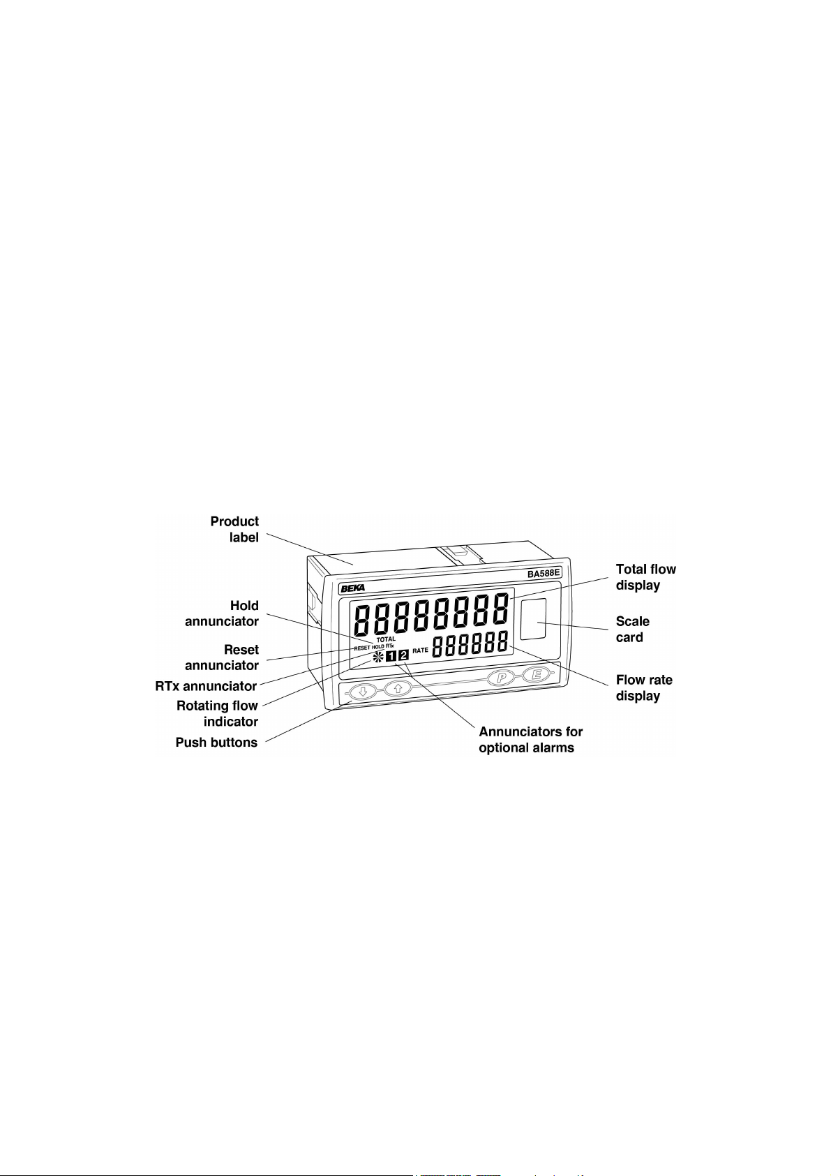
The BA588E's units of measurement are shown on a
printed scale card in a window at the right hand side
of the display. The scale card is mounted on a
flexible strip that is inserted into a slot at the rear of
the instrument as shown in Fig 5. Thus the scale
card can easily be changed without removing the
BA588E Rate Totaliser from the panel or opening the
instrument enclosure.
New instruments are supplied with a printed scale
card showing the requested units of measurement, if
this information is not supplied when the instrument
is ordered a blank card will be fitted.
A pack of self-adhesive scale cards printed with
common units of flow measurement is available as
an accessory from BEKA associates. Custom
printed scale cards can also be supplied.
To change a scale card, unclip the tapered end of
the flexible strip at the rear of the instrument by
gently pushing it upwards and pulling it out of the
enclosure. Peel the existing scale card from the
flexible strip and replace it with a new printed card,
which should be aligned as shown below. Do not fit
a new scale card on top of an existing card.
Install the new scale card by gently pushing the
flexible strip into the slot at the rear of the
instrument, when it reaches the internal end-stop
secure it by pushing the end of the flexible strip
downwards so that the tapered section is held by the
rear panel.
Align the self-adhesive printed scale
card onto the flexible strip and insert
the strip into the instrument as
shown below.
Fig 5 Inserting the flexible strip carrying the scale
card into slot at the rear of the instrument.
5.0 CONFIGURATION AND CALIBRATION
The BA588E Rate Totaliser is configured and
calibrated via four front panel push buttons. Figs 6
and 7 show the calibration structure and the
configuration menu.
Each menu function is summarised in section 5.3 of
this manual and each summary includes a reference
to more detailed information. The two sixteen
segment linearisers and the pulse output are
described separately in sections 6 and 7.
When factory fitted optional alarms and a 4/20mA
output are included, additional functions appear in
the configuration menu which are described
separately in sections 10.3 and 10.5.
All new BA588E Rate Totalisers are supplied
calibrated as requested at the time of ordering. If
calibration is not requested, Rate Totalisers will have
default configuration which is shown in the following
table, but can easily be re-configured on-site.
Function Display Default
Access code CodE 0000
Function FunCtion 5td
A Input* inP .tYPE-A oP.CoL
Debounce dEbounCE dEFAuLt
Update uPdAtE 0 .5
Count Count A :b
Upper display di5p-1 totAL
Lower display di5P-2 5td
Decimal point dP Total00000000
Rate 0000.0
Factor input A* FACtor-A 001 .00
Total scale factor input A* 5cALE .T-A 001 .00
Rate scale factor input A* 5cALE .R-A 001 .00
Timebase t-bA5E tb-01(secs)
Filter for input A* FiLter-A 24
Clip-off for input A* CLP .oFF-A 0000.0
Local total reset Clr tot oFF
Local grand total reset Clr Gtot oFF
Pulse source 5ource 5caled
divide 1
duration 0 .1
External reset E clr clr anb
Access code CodE 0000
Notes:
1. Defaults for input A are shown, defaults for
input b are identical, functions affected are
identified with an *.
2. While the instrument is being configured
totalisation continues so that any flow
occurring during this time is recorded.