Belanger Gyro Wrap Signature Series User manual
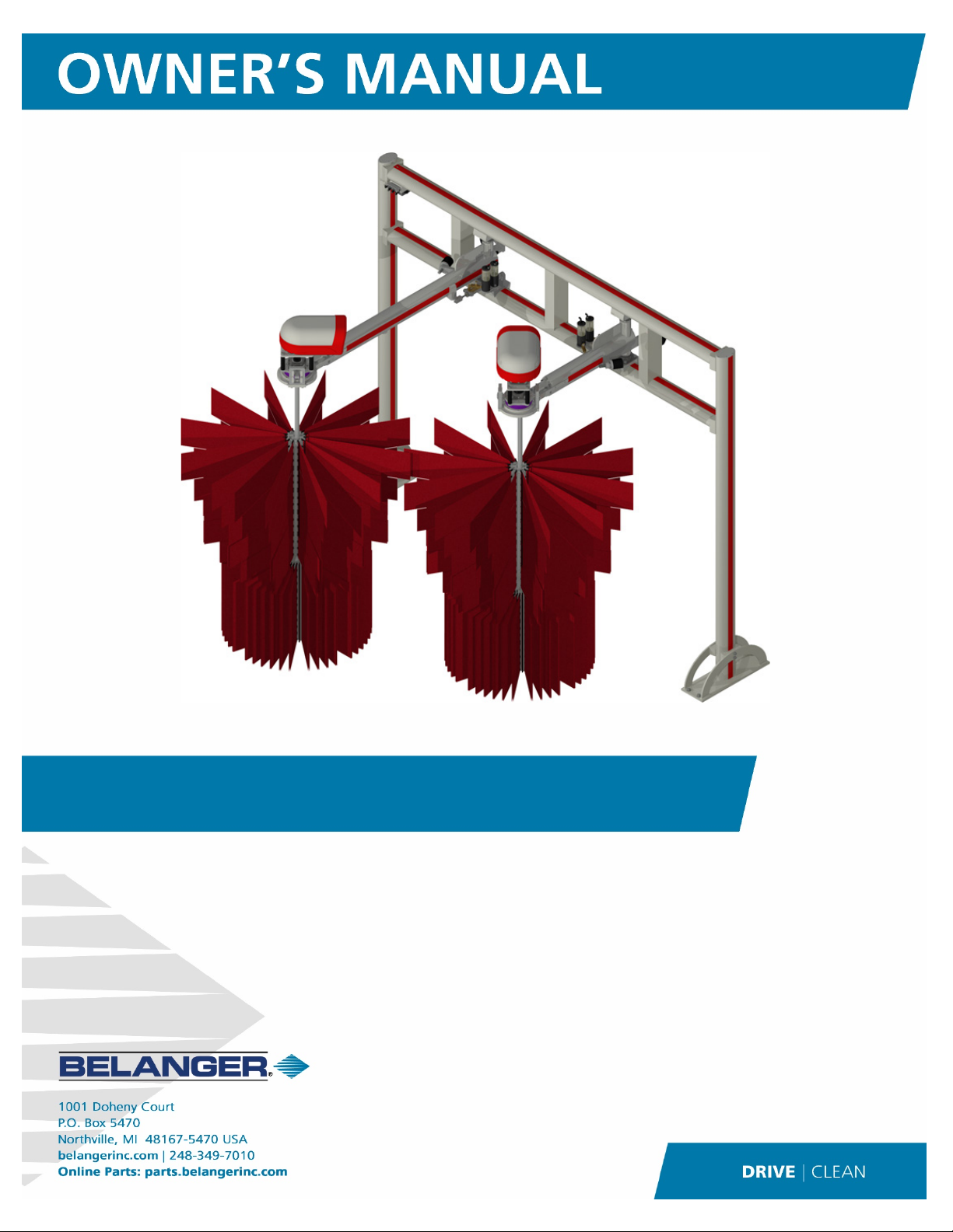
Gyro Wrap™ Signature Series
Gyro Wrap™ Signature Series
1MANUAL248 Rev02


Belanger Equipment Owner’s Manual
Gyro Wrap™ Signature Series
Copyright 2021
Belanger, Inc®
This manual and the accompanying equipment are protected by United States trademark, copyright, and patent laws. You
may make one copy of this manual. Do not make additional copies of this manual or electronically transmit it in any form
whatsoever, in whole or in part, without the prior written permission of Belanger, Inc.®
The registered trademarks used in this document are the property of their respective owners. The use of such trademarks is
for reference purposes only and does not imply sponsorship or approval of Belanger, Inc.®by these companies or any
companies affiliated with their respective owners.


CURRENT REVISION LOG
Belanger, Inc. * PO BOX 5470 *Northville, MI 48167-5470 * Ph (248) 349-7010 * Fax (248) 380-9681 1MANUL248
Rev
Release
Date
Page Description
02
Before
4/8/21
All Changed Neo-Tex to Neo-Tex™ throughout manual
3
Updated Limited Warranty
7
Added “or hydraulic” to the first sentence of the second paragraph
Removed the first sentence from the third paragraph which specified the electric motor
specifications
Removed the Neo-Tex™ Foam and cleaning information from the Introduction
In the first paragraph changed Belanger Signature Line to Belanger® Signature® and
removed “to a glossy white” after powder coated
8
Removed Gearbox from Motor-Gearbox Assemblies under Equipment included
9
Changed dimension under Tunnel space required from 129-1/2” to 139”
Removed “plastic” and “cover” under Unit height
Added “each motor” after each of the motor specifications
Added Hydraulic 4GPM @900 PSI to the Utility section
Added Unit Height 126”: from the floor to the top of the hoses – Hydraulic
Changed CAUTION note from …installing piece of equipment to …installing a piece of
equipment
10
Added Electric and Hydraulic to subheading
Changed dimension 129-1/2” to 139” and 135-1/2” to 145”
Added image to show Unit Height for a Hydraulic system
11
Removed “Electric” from heading Drive Considerations
Added Electric and Hydraulic to sub-heading
Added image of hydraulic motor assembly
12
Changed Electrical to Electric in subheading
Changed Note from There are driver side / passenger side labels to There is a driver side
and passenger side label…
Changed image title to Overview of the correct orientation for Gyro Head with an Electric
Motor/Gearbox
13
Added this page to describe and show the Gyro Head™ Orientation for the hydraulic
motor
14
Revised Frame Assembly steps 2-6 per the attached document
15
Added Guide Rail after Conveyor in note
19-22
Added Electric Drive Only to the sub-heading
20
Added note to verify that the overall length of the two shafts is 102”
Corrected spelling in step 1
22-25
Added Inserting the Shaft – Hydraulic Drive Only instructions and images
26-29
Added Electric Drive Only to the sub-heading Mounting the Motor/Gearbox Assembly
32-36
Revised instructions for the installation of the Neo-Tex™ Fill (per Change Request #38)
Removed installation instructions for Neo-Tex
™
with Nylon Brush fill
33
Under Installing Cleaning Material Lower Hub Fill step 5 changed 8” to 10” Wash Clips
34
Under Installing Cleaning Material for Upper Hub: Neo-Tex™ in step 5 changed “Clips” to
“Clip” and “if both packs” to “of two pieces”
37-44
Added Hydraulic to the Utilities sub-heading
Changed sub-heading to Pneumatic, Electric or Hydraulic, and Water
37
Added Note for hydraulic driven machines to disregard the electrical routing and
connection steps
Updated the Distribution Manifold – Electric images
Added images of the Distribution Manifold – Hydraulic
Added Electric and Hydraulic notes to images in step 2
38
Changed the last sentence in first paragraph from “…each end for all” to “…the end of
each” and connections to connection
Updated the images of the distribution manifold and the pneumatic connections

CURRENT REVISION LOG
Belanger, Inc. * PO BOX 5470 *Northville, MI 48167-5470 * Ph (248) 349-7010 * Fax (248) 380-9681 1MANUL248
Rev
Release
Date
Page Description
40
Under Pneumatic Connections removed Passenger Side from step 4c
Changed “4 wire electrical cord” in Note to “4 conductor cable”
Under Electrical Junction Box Connections step 1 changed electrical to electrician and in
step 1c removed Passenger Side:
41
Updated the image of the distribution manifold in Step 2 of Electrical Junction Box
Connections
Removed the first word “Supplies” from the first paragraph of the Electrical Motor/Gearbox
Connections section
Added images to Electrical Motor/Gearbox Connections step 1 and in step 2 changed 4
wires to 4 conductor cable
Replaced “If you have the optional motor covers, you will need to…” with “Then…”
42
Changed “wired up” to “connected” in the first sentence under Wheel Rotation
Changed the sentence: Use the image for... to Refer to the image at the bottom of this
page for…
Changed “Turn power off swap motor leads if necessary.” to “If the wheels are rotating
incorrectly turn the power off and swap the motor leads.”
Corrected typo in Note: show to shown
Removed Water Manifold Installation section under Utilities; manifold ships secured in
position
43
Added Connecting the Hydraulic Hoses instructions and images under Utilities section
45
Changed filler strip part numbers: 8812 to 9317 and 8805 to 9310
46
Changed filler strip lengths: at base of frame legs from 7-3/4” to 7-7/8” in four places, on
top of the head assembly from 67-13/16” to 15-1/16”, on top of the passenger side arm
assembly from 43-1/4” to 33-1/2” and added a 7-3/4” filler strip
48
Removed the third sentence in the first paragraph under Swing Flow Control which stated:
On each stand, there are two such controls.
50
Removed and added Daily, Weekly and Monthly Routine Procedures
Removed Quarterly Routine Procedures
50-52
Added the Powder Coating Maintenance and Powder Coating Repair Procedures
55
Added exploded views of the Head Assembly with Hydraulic Lines
56
Added exploded views of the Arm Assemblies with Hydraulic Lines
57
Changed part numbers: 1BERNG810 to 1BERNG849 in two places, 1GRMIT750 to
1GRMIT666, 8767 to 9298 and 8778 to 9299
Corrected part number: 1WASHR-LC281 to 1WASHR-LC581
58
Removed Hydraulic from the first subheading on the page
Changed second subheading from Gyro Head Assembly: Hydraulic to Gyro Cylinder
Assembly: 109721 & 109722
59
Changed subheading from Gyro Head Assembly: Hydraulic to Gyro Cylinder Assembly:
109721 & 109722
Changed subheading from Posi-Stop Mount Assembly: 109722 to Gyro Cylinder
Assembly: 109721 & 109722
Changed part number 1VALVE-HY393 to 1VALVE-HY395 (per Change Request #11)
60
Added exploded views of the electrical and hydraulic distribution manifolds
Added “see below” to component callouts
Added 109712 and 109713 to subheading and component callouts
61
Added 60 Hz into the following subheading Gyro Head Assembly: Electric 60Hz (Upper
Section)
Added the number 1 to all the plastic gear cover part numbers in chart
62
Replace with a new exploded assembly to include the 1FSTNR-SH958(4) fasteners
Corrected part numbers: 8781 was 3211, 1BERNG849 was 1BERNG810 (2 places), 8783
was 8738,
63
Added this page to show the exploded view of the Gyro Head Assembly for the 50 Hz
electric motor, drive shaft and assembled image

CURRENT REVISION LOG
1MANUL248 Belanger, Inc. * PO BOX 5470 *Northville, MI 48167-5470 * Ph (248) 349-7010 * Fax (248) 380-9681
Rev
Release
Date
Page Description
64
Added this page to show the exploded view of the Gyro Head Assembly for the hydraulic
motor, drive shaft and the exploded view of mounting the hydraulic motor
65
Changed subheadings from Air Cylinder Assembly to Water Manifold Assembly and Air-
Over-Oil Assembly to Water Manifold Assembly Components
Created new images to show the entire water manifold assembly and exploded images to
show components of the assembly
66
Changed filler strip part number 8812 to 9317 and 8805 to 9310
Changed filler strip lengths: at base of frame legs from 7-3/4” to 7-7/8” in four places, on
top of the head assembly from 67-13/16” to 15-1/16”, on top of the passenger side arm
assembly from 43-1/4” to 33-1/2” and added a 7-3/4” filler strip
68
Added part number callout 1VALVE-EL710 (per Change Request 60)
71
Added page to show part numbers for the plastic Wash Clips for Neo-Tex™ and the Neo-
Tex
™
Fill Pattern (per Change Request #38)
72
Moved line to the correct position to show the top three sections
Removed note about the bottom row of lower hub having 20 additional clips
Added: hub sizes and part numbers, single part numbers for Neo-Tex™, part numbers for
complete Neo-Tex™ fill replacement for all six colors, wash clip quantities for upper and
lower hubs (per Change Request #38)
73-75
Added Appendix A: Nylon Brush Installation for Fleet Washes. This content was
previously included within the manual, it is an offering primarily for Rental Car Fleet
Washes.
2
After
04/08/21
11 Removed the description of passenger side and driver side sticker label
12 & 13 Increased size of the driver side and passenger side identification note
14 Called out the Clevis Mount
15
Added Note: The 48-3/4” measurement is the same for both a single and a double
guiderail conveyor.
17 Identified what arm was being mounted in the image
18 Added notes about cylinder installation and how to adjust the flow control properly
26 Added note about plastic motor cover option for 60Hz Motor/Gearbox Assembly
27 Added note about loosening the Torque Studs to set the Cotter Pins when installing the
electric Motor/Gearbox then retightening the Torque Studs
54
Added not stating that the Leg Assembly Caps may have either 2 or 6 fasteners, the older
assemblies have 6 and the newer assemblies have 2
58
Updated the image of the Gyro Bearing Glide Components
61
Updated page to show 8-hole Torque Plate 108661
Added enlarged image of Torque Plate & Ring Terminals
Changed Motor/Gearbox call out from: 1GEABX-AS986: Std. Voltage, 1GEABX-AS988:
575 Volts to 112286 Std. VAC, 112297: 380/400/415 VAC, 112288: 575VAC per
62
Updated the Electric 60Hz Head Assembly to clarify the B-Ball Assembly 109725 &
Motor/Gearbox Assembly, specified black powder coated parts
63
Updated the Electric 50Hz Head Assembly to clarify the B-Ball Assembly 110245 &
Motor/Gearbox Assembly 110246, specified black powder coated parts
64
Updated the Hydraulic Motor/B-Ball Head Assembly 110342, specified black PC parts
69
Changed part number 1FSTNR-HH045 to 1FSTNR-HH056


GYRO WRAP™ Signature ®Series
1MANUL248 Belanger, Inc. *PO BOX 5470 *Northville, MI 48167-5470 * Ph (248) 349-7010 * Fax (248) 380-9681 1
Table of Contents
Belanger Incorporated Limited Warranty........................................................ 3
Operational Warning......................................................................................... 4
Introduction ....................................................................................................... 5
Important Safety Information................................................................................................................................... 5
Safety Symbols and Signal Words.......................................................................................................................... 5
Safety Warnings...................................................................................................................................................... 6
Before You Get Started........................................................................................................................................... 8
Specifications.................................................................................................... 9
Requirements.......................................................................................................................................................... 9
General Dimensions: Electric and Hydraulic......................................................................................................... 10
Drive Considerations ...................................................................................... 11
Wash Module ........................................................................................................................................................ 11
Electric and Hydraulic Motor Assembly Component Orientation........................................................................... 11
Installation ....................................................................................................... 12
Gyro Head™ Orientation - Electric........................................................................................................................ 12
Gyro Head™ Orientation - Hydraulic..................................................................................................................... 13
Tunnel Placement ................................................................................................................................................. 14
Frame Assembly ................................................................................................................................................... 14
Attaching the Arms and Cylinders......................................................................................................................... 16
Attaching the Spherical Bearing Assembly – Electric Drive Only.......................................................................... 19
Inserting the Shaft – Electric Drive Only................................................................................................................ 20
Inserting the Shaft – Hydraulic Drive Only ............................................................................................................ 22
Mounting the Motor/Gearbox Assembly – Electric Drive Only .............................................................................. 26
Installing Side Wheel Hubs ................................................................................................................................... 30
Lower Hub Installation Overview...........................................................................................................................................30
Lower Hub Installation...........................................................................................................................................................30
Upper Hub Installation...........................................................................................................................................................31
Installing Cleaning Material ................................................................................................................................... 31
Cleaning Material Orientation................................................................................................................................................31
Lower Hub Fill........................................................................................................................................................................33
Upper Hub: Neo-Tex™..........................................................................................................................................................34
Utilities: Pneumatic, Electric or Hydraulic, and Water ........................................................................................... 37
Installing the Remaining Filler Strips..................................................................................................................... 45
Adjusting the Positive Stops.................................................................................................................................. 47
Operational Performance and Controls ........................................................ 48
Understanding Air-Over-Oil ................................................................................................................................... 48
Understanding Regulator Adjustments.................................................................................................................. 48
Initial Start Up.................................................................................................. 49

GYRO WRAP™ Signature ®Series
2Belanger, Inc. * PO BOX 5470 *Northville, MI 48167-5470 * Ph (248) 349-7010 * Fax (248) 380-9681 1MANUL248
Table of Contents
Maintenance .....................................................................................................50
Routine Procedures ...............................................................................................................................................50
Powder Coating Maintenance................................................................................................................................50
Powder Coating Repair..........................................................................................................................................51
Trouble Shooting....................................................................................................................................................52
Exploded Parts View..............................................................................................................................................53
Frame Main Components ......................................................................................................................................................53
Leg Assembly: 109717 ..........................................................................................................................................................54
Arm Weldments .....................................................................................................................................................................54
Head Assembly with Hydraulic Lines ....................................................................................................................................55
Arm Assemblies with Hydraulic Lines....................................................................................................................................56
Arm Mounting Components ...................................................................................................................................................57
Head Mounting Components.................................................................................................................................................57
Head Mounting & Gyro Bearing Glide Components..............................................................................................................58
Gyro Cylinder Assembly: 109721 & 109722..........................................................................................................................58
Distribution Manifold Assembly..............................................................................................................................................60
Posi-Stop Mount Assembly....................................................................................................................................................60
Gyro Head Assembly: Electric 60Hz (Lower Section) ...........................................................................................................62
Gyro Head Assembly: Electric 50Hz .....................................................................................................................................63
Gyro Head Assembly: Hydraulic............................................................................................................................................64
Water Manifold Assembly ......................................................................................................................................................65
Water Manifold Assembly Components ................................................................................................................................65
Filler Strips.............................................................................................................................................................................66
Gyro Wrap Air Panel..............................................................................................................................................................67
Aluminum Hub Assembly (Overview) ....................................................................................................................................68
Aluminum Hub Assembly (Upper Section): 106782 ..............................................................................................................69
Aluminum Hub Assembly (Lower Section): 106026 ..............................................................................................................70
Neo-Tex™ Wash Clips ..........................................................................................................................................................71
Aluminum Hub Neo-Tex™ Fill ...............................................................................................................................................72
Appendix A: Nylon Brush Installation for Fleet Washes ..............................73
Installing Cleaning Material....................................................................................................................................73
Overview for Neo-Tex™ with Nylon Brush Packs .................................................................................................................73
Exploded Parts View..............................................................................................................................................75
Aluminum Hub Neo-Tex™ Fill with Nylon Brush Packs ........................................................................................................75

GYRO WRAP™ Signature ®Series
1MANUL248 Belanger, Inc. * PO BOX 5470 *Northville, MI 48167-5470 * Ph (248) 349-7010 * Fax (248) 380-96813
Belanger Incorporated Limited Warranty
LIMITED WARRANTY:
Equipment:
Subject to the limitations stated below, Seller warrants that the Equipment sold hereunder, which is fabricated by
Seller, shall be free from defects in workmanship and material under normal use and service for a period of 1 year plus
30 days from the date of invoice - CATPumps will be warranted for 2 years from the date of invoice.
Parts:
Subject to the limitations stated below, Seller warrants that the Parts sold hereunder, shall be free from defects in
workmanship and material under normal use and service for a period of 90 days from the date of invoice.
Limitations on All Warranties:
The warranties contained in this Section 13 are subject to the following limitations: (1) they are void if the factory
specifications for operation and maintenance, found in original equipment manuals, and component manuals, are not
followed, or if other than factory authorized erection, alterations or modifications are made to any Parts or Equipment;
(2) defective Parts are warranted to the Purchaser only for repair or replacement through an authorized Purchaser or
Distributor of Seller, or direct with Seller for a period of 13 months from the date of invoice; however, this warranty
excludes all claims for failure resulting from normal wear and tear, improper installation, omission of factory specified
preventative maintenance, misuse, abuse, negligence, third party damages, or acts of God and Purchaser agrees to
submit to and assist Seller or its authorized Purchaser or Distributor in conducting in-warranty inspections of the
Goods including inspection of any Equipment or Parts claimed to be defective by the Purchaser; (3) the cost of
providing labor or repair to replace Equipment and Parts warranted to Purchaser will be included within the warranty
only if such claim is made within 120 days from the date of invoice and then only during normal business hours
through an authorized Purchaser or Distributor of Seller, or direct with Seller, and labor and service provided beyond
the labor warranty period shall be subject to labor charges at the rates established by the local authorized Purchaser
or Distributor or direct with Seller; (4) the warranties shall be void for all Equipment failures and premature Part wear
caused by the use of corrosive chemicals in the wash process, and the following list includes some, but not all, of the
particularly corrosive chemicals that if used in conjunction with Equipment or Parts will void the warranty: Hydrofluoric
Acid, Ammonium Bi-fluoride, Bromic Acid, Muriatic Acid, Sulfonic Acid, Phosphoric Acid, Hydrogen Cyanide,
Hydrochloric Acid, Sodium Hydroxide and Chlorinated Solvents; (5) Seller makes no warranty, express or implied, with
respect to the design or operation of any entire system, in which Seller’s Equipment or Parts sold hereunder are mere
components;(6) in no event shall Seller be liable for any incidental, special, consequential, punitive or exemplary
damages resulting from the furnishing, performance or use of any Goods or services sold pursuant hereto, whether
due to a breach of contract, breach of warranty, negligence or any other claim at law or equity. Seller shall not be
liable for any damages of any kind, including, but not limited to, loss of business; inconvenience, or property damage
of any kind; nor for any damages of whatever nature resulting in any way from the Purchaser’s selection and use of
any chemicals not manufactured exclusively by Seller but used with the purchased Equipment or Parts; or for any
service not expressly provided herein related to or arising from the Equipment or Parts sold. Seller shall not be liable
for damages resulting from Purchaser’s use of any engineering recommendations, sales representations, technical
assistance, advice or data other than that information contained in Belanger manuals; (7) all warranties, express,
implied, or statutory, pertaining to the Equipment and Parts apply to the Purchaser only; are not transferable; are fully
set forth herein; and no addition to or modification thereto shall be binding upon the Seller, unless made in writing and
signed by a duly authorized employee of Seller.
No Other Warranties:
THIS LIMITED WARRANTY FOR EQUIPMENT AND PARTS IS EXPRESSLY IN LIEU OF ALL OTHER
WARRANTIES, EXPRESS OR IMPLIED, WHETHER STATUTORY OR OTHERWISE, INCLUDING ANY
IMPLIED WARRANTY OF MERCHANTABILITY OR WARRANTY OF FITNESS FOR A PARTICULAR
PURPOSE. THE IMPLIED WARRANTIES OF MERCHANTABILITY AND FITNESS FOR PARTICULAR
PURPOSE CONTAINED IN THE UNIFORM COMMERCIAL CODE – SALES ARE EXPRESSLY
DISCLAIMED.
Copyright ©2020 by Belanger, Inc. All rights reserved. No part of this work may be reproduced or transmitted in any
form or by any means, electronic or mechanical, including photocopying and recording, or by any information storage
or retrieval system, except as may be expressly permitted by the 1976 Copyright Act. Belanger reserves the right to
change or modify the Belanger Inc. Limited warranty without notice.

GYRO WRAP™ Signature ®Series
4Belanger, Inc. * PO BOX 5470 *Northville, MI 48167-5470 * Ph (248) 349-7010 * Fax (248) 380-9681 1MANUL248
Operational Warning
Formulations containing the chemicals listed below are particularly dangerous and should not
be used even at low concentrations:
•Hydrofluoric Acid
•Ammonium Bi-fluoride
•Bromic Acid
•Muriatic Acid
•Sulfonic Acid
•Phosphoric Acid
•Hydrogen Cyanide
•Hydrochloric Acid
•Chlorinated Solvents
Belanger, Inc., does not endorse or condone the use of chemicals that are potentially
dangerous to human health, the environment or property. Belanger recognizes that it is the
right and sole decision of the end user operators of our equipment as to the type and dilution
ratio of the chemicals used in their facilities. We strongly recommend that the end user does
not select products containing any of the chemicals listed above as an ingredient in the wash
solutions. The chemicals listed above are potentially dangerous to human health, and have a
detrimental, deteriorating effect on the equipment and the facility. Be advised that a portion of,
or all of your warranty will be voided if you determine to use any of the chemicals listed above
as an ingredient in the wash solutions in conjunction with your Belanger automatic car wash
equipment:
Limitation (4), of Paragraph (8), Limited Warranty, of the Belanger Terms and Conditions of
Sales describes the potential limitation of warranty due to your chemical selection:
(4) This warranty shall be void for all equipment failures and premature component wear
caused by the use of corrosive chemicals in the wash process. The following list includes
some, but not all, of the particularly corrosive chemicals that if used in conjunction with
Belanger equipment will void the warranty: Hydrofluoric Acid, Ammonium Bi-fluoride, Bromic
Acid, Muriatic Acid, Sulfonic Acid, Phosphoric Acid, Hydrogen Cyanide, Hydrochloric Acid,
and Chlorinated Solvents. The Purchaser also agrees to accept the responsibility and
liability for the selection and use of any chemicals listed above.
However, should the end user decide to use formulations containing any of the above
ingredients, the end user should institute a comprehensive training program and implement
detailed operational parameters within their organization for the proper handling and treatment
of such products to minimize the potential dangers involved. Consult your chemical supplier for
assistance in establishing operational guidelines in the use of their products. MSDS (Material
Safety Data Sheet) should be obtained from the chemical supplier before using any chemical
formulation.
During the installation process the installer is responsible for re-tightening
ALL lugs, set screws and terminals located in the electrical panels. Components
may vibrate loose during shipping.

GYRO WRAP™ Signature ®Series
1MANUL248 Belanger, Inc. * PO BOX 5470 *Northville, MI 48167-5470 * Ph (248) 349-7010 * Fax (248) 380-96815
Introduction
Important Safety Information
This section introduces the hazard and safety precautions associated with installing, maintaining or
servicing this product. Before performing any task on this product, read this safety information and
the applicable sections in this manual, where additional hazards and safety precautions for your task
may be found. Electrical shock could occur and cause death or serious injury if these safe service
procedures are not followed.
Safety Symbols and Signal Words
Alert Symbol
This safety alert symbol is used in this manual and on warning labels to alert you to
precautions, which must be followed to prevent potential personal safety hazards.
Obey safety directives that follow this symbol to avoid possible injury or death.
Signal Words
The signal words used in this manual and on warning labels tell you the seriousness of
particular safety hazards. The precautions that follow must be followed to prevent death, injury
or damage to the equipment.
This signal word is used to alert you to a hazard or unsafe practice which WILL RESULT IN
DEATH OR SERIOUS INJURY
This alerts you to a hazard or unsafe practice which COULD RESULT IN DEATH OR
SERIOUS INJURY
This signal word designates a hazard or unsafe practice, which MAY RESULT IN MINOR
INJURY
When used by itself, CAUTION designates a hazard or unsafe practice, which MAY RESULT
IN PROPERTY OR EQUIPMENT DAMAGE
Before You Begin
Only trained or authorized individuals knowledgeable in the related procedures should install,
inspect, maintain or service this equipment.
Read the Manual
Read, understand and follow this manual and any other labels or related materials supplied with
this equipment. If you do not understand the procedure, call a Belanger, Inc. representative at
248-349-7010. It is imperative to your safety and the safety of others to understand the
procedures before beginning work.
GYRO WRAP™ Signature ®Series
6Belanger, Inc. * PO BOX 5470 *Northville, MI 48167-5470 * Ph (248) 349-7010 * Fax (248) 380-9681 1MANUL248
Introduction
IMPORTANT Safety Information – MUST READ
Safety Warnings
DISCONNECT MAIN POWER SUPPLY PRIOR TO
SERVICING OR MAINTAINING EQUIPMENT
Belanger recommends that all workers observe the OSHA (U.S. Department
of Labor Occupational Safety & Health Administration) Lockout / Tagout
procedure prior to performing service or maintenance on machinery and
equipment. Doing so will prevent unexpected energization, startup, or
release of hazardous energy while maintenance and servicing activities are
being performed.
BE SURE TO OBSERVE OPERATING ENVELOPE.
EQUIPMENT MAY START UNEXPECTICALLY. OVERHEAD,
ROTATING AND/OR MOVING COMPONENTS COULD
RESULT IN SERIOUS INJURY OR DEATH.
BE AWARE OF FOREIGN OBJECTS IN THE AREA
SURROUNDING A ROTATING PIECE OF EQUIPMENT.
OBJECTS MAY BECOME TANGLED WITH EQUIPMENT AND
COULD RESULT IN SERIOUS INJURY OR DEATH.
BE AWARE OF HAZARDS ASSOCIATED WITH
EQUIPMENT INSTALLED ON THE FLOOR
THAT MAY BE A TRIP HAZARD.
It is imperative to your safety and the safety of others to always follow safe work procedures.
GYRO WRAP™ Signature ®Series
1MANUL248 Belanger, Inc. * PO BOX 5470 *Northville, MI 48167-5470 * Ph (248) 349-7010 * Fax (248) 380-96817
Introduction
Congratulations on your purchase of the Belanger® Signature® Gyro Wrap. All the main frame
components and the arm components are constructed of aluminum and then powder coated. The
powder coat finish will give the machine a fresh new look for many years and is easier to maintain
and clean. The hub shafts are constructed of a high strength stress proof steel and then cadmium
plated for added corrosion resistance.
The Signature® Gyro Wrap is offered as an electric or hydraulic drive machine. The arms are
controlled by a single air panel which is then connected to a single air-over-oil system for each arm
assembly. The air-over-oil system then utilizes a flow control valve on the extend and retract ports of
the cylinder to ensure a smooth and consistent stroke every cycle.
Whether you have already operated a car wash, or you are new to our industry, you know the
importance of the appearance of a car wash and its equipment to the customer.
Read through the entire manual to familiarize you with the Gyro Wrap™ before installation. When
installation is completed, you will want to keep this manual as a guide to proper maintenance.
It is imperative that wheels are spinning during any period that the
conveyor is activated.

GYRO WRAP™ Signature ®Series
8Belanger, Inc. * PO BOX 5470 *Northville, MI 48167-5470 * Ph (248) 349-7010 * Fax (248) 380-9681 1MANUL248
Introduction
Before You Get Started
Tools needed for installation:
Forklift (with side shift if available) C-Clamps
Hammer drill with 5/8” bit Tin snips
Tape measure (25 foot or greater) Safety glasses
Miscellaneous hand tools Work gloves
Level 50-foot extension cord
Ladder
Equipment included: Qty
Head Beam Frame Assembly 1
Driver Side Arm Assembly 1
Passenger Side Arm Assembly 1
Leg Assemblies 2
Large Diameter Hub Assemblies: 28-1/4” long 2
Small Diameter Hub Assemblies: 42-1/4” long 2
Steel hub Shafts 2
Spherical Bearing Assemblies 2
Motor Assemblies 2
Lower Hub Neo-Tex™ Clips 1 box
Upper Hub Neo-Tex™ Clips 1 box
Filler Strip Kit 1
Neo-Tex™ Cleaning Material 8 boxes
Accessory box 1
Note: Uncrate and inspect shipment for damage, and to verify that all pieces are there. If there is
any damaged equipment, file a claim with the trucking company immediately. Receiving
party is responsible for filing claim with trucking company. Notify your local distributor or
Belanger, Inc. immediately If shipment is determined damaged or incomplete.
GYRO WRAP™ Signature ®Series
1MANUL248 Belanger, Inc. * PO BOX 5470 *Northville, MI 48167-5470 * Ph (248) 349-7010 * Fax (248) 380-96819
Specifications
Requirements
Physical
Tunnel space required
Unit Length: entrance side of the base plate to the outermost tip of
Neo-Tex™ on the passenger side wheel – 139”
Unit width
151-1/2”: outside to outside of base plates
Unit height
120”: from the floor to the top of the motor - Electric
126”: from the floor to the top of the hydraulic hoses - Hydraulic
Vehicle height clearance
90”
Utility
Electrical
1 HP; 208-230/460 V; 60 Hz – each motor
1 HP; 575 V; 60 Hz – each motor
2 HP; 208-230/460 V; 50 Hz – each motor
Pneumatic
0.3 CFM @ 90-120 PSI maximum
Hydraulic
4 GPM @ 900 PSI
Water
2.8 GPM total or 1.4 GPM per side @ 40 PSI
DISCONNECT AND LOCKOUT ELECTRICAL POWER BEFORE SERVICING ANY
EQUIPMENT!
Always wear safety glasses when performing maintenance on any equipment
It is recommended that a licensed electrician is contracted to perform all electrical installations.
YOUR HYDRAULIC SYSTEM MUST BE CAPABLE OF ADJUSTMENT TO 76 RPM AT
900 PSI (62.1 BAR) WHILE LOADED AGAINST VEHICLE. PLEASE VERIFY YOUR
SYSTEMS CAPABILITY TO MEET THESE SETTING WHILE RUNNING A VEHICLE
PRIOR TO INSTALLING A PIECE OF EQUIPMENT
A compressed Air System should be set correctly to support 90 PSI necessary to operate
equipment but should never be set to deliver more than 120 PSI air pressure to the Belanger
specified equipment.

GYRO WRAP™ Signature ®Series
10 Belanger, Inc. * PO BOX 5470 *Northville, MI 48167-5470 * Ph (248) 349-7010 * Fax (248) 380-9681 1MANUL248
Specifications
General Dimensions: Electric and Hydraulic
145" dimension allows 6” clearance from the cleaning material
Unit Height for
Hydraulic Only
151-1/2”
145”
48-3/4”
This dimension is taken from the outside edge
of the Base Plate to the inside edge of the
inside Conveyor Guide Rail
139”
126”
120”
Table of contents
Other Belanger Cleaning Equipment manuals

Belanger
Belanger DuoScrubber User manual

Belanger
Belanger FreeStyler E-1032 User manual

Belanger
Belanger DuoScrubber HP User manual

Belanger
Belanger Wave Across User manual

Belanger
Belanger FreeStyler User manual

Belanger
Belanger Full Side Washer User manual

Belanger
Belanger QuickFire User manual

Belanger
Belanger QuickFire Wrap Around Signature Series User manual

Belanger
Belanger DURAJET ARCH User manual

Belanger
Belanger SUDZAMELEON ARCH User manual


