Bell'O 8335 User manual
English
Introduction
Congratulations on your decision to mount your TV with a TV Wall Mounting Kit For
Dummies. The enclosed mounting bracket was engineered and designed by Bell’O
International Corporation using the latest computer-aided design and stress-analysis
software to ensure safety and durability when installed according to the instructions. It
has been further tested and Listed by Underwriters Laboratories.
About This Manual
Mounting your TV on the wall can seem like an overwhelming task. This handy For Dummies®
guide takes you through the process step-by-step to ensure the proper installation of your
mount. Before starting this project, be sure to read the entire instruction manual and watch the
included installation DVD for a complete demonstration. If at any time you are unclear about
the directions and believe you need further assistance, contact the Bell’O®installation experts
at 888-779-7781 from 9am – 5pm EST.
Icons Used in This Book
Don’tbe alarmed by the bomb in the icon. We just want to
get your attention because making an error could be costly.
This is not really very technical stuff, just some details you
need to really pay attention to.
Foolish Assumptions
Although our easy-to-install mounts and instructions simplify the process, mounting your
TV still requires great care. Weassume you’re someone who, at minimum, has done odd
jobs around the house and has some basic tools. You don’t need to be a master carpenter or
electrician to install this mount. With that said, if at any time you feel that you are
uncertain or uncomfortable with doing the installation yourself, don’t hesitate to call on a
handyman or professional contractor/installer.

English
NEVER exceed the maximum load capacity of 280 lbs (127 kg)
Precautions!
•This mounting bracket was designed to be installed and utilized ONLY
as specified in this manual. Bell’O International Corporation will not
be responsible for failure to assemble as directed or for the improper
assembly, use, or handling of this product.
•Improper installation of this product may cause damage or serious
injury. Bell'O International Corporation cannot be liable for direct or
indirect damage or injury caused by incorrect mounting, incorrect
use, or incorrect assembly.
•If the mounting bracket will be attached to any structure other than
those specified in this manual, only a licensed professional
contractor/installer should perform this installation. The supporting
structure must support, at minimum, four times the combined weight
of the mounting bracket and TV. It is the responsibility and liability of
the installer to ensure the suitability of the supporting structure.
•This product should NEVER be mounted to metal framing studs.
•Check carefully to ensure that there are no missing or damaged parts.
Never use defective parts. If any parts are damaged or missing, call
Bell'O International Corporation at 888-779-7781 and parts will be
shipped directly to purchaser. Please contact Bell’O International Corp.
beforeattempting to returnproducts to the point of purchase.
•Specifications are subject to change without notice.
•The maximum weight of your television cannot exceed the maximum
weight rating of your mount or any attached Bell'O®UL listed adapters
sold separately, whichever is lower.

(WP) Wall Plate (with Left & Right Extensions), Qty: 1
(EC) End Covers, Qty: 2
(ME) Arm Extensions, Qty: 4
Parts Included in This Kit
(MA) Monitor Arms, Qty: 2
English
(IT) Installation Template, Qty: 1
(IG) Installation Guide
&DVD, Qty: 1 each
Quite possibly the world’s
easiest mounts to install!
For 8335Mounting Bracket
English Français Español
Installation Guide for
TV Wall Mounting Kit
A step-by-step guide for
mounting your flat panel
TV safely and easily!
Installation Video for
Bell’O TV Wall Mounting Kits
©
J
a
n
u
a
r
y
2
0
0
7
B
e
l
l
'
O
I
n
t
e
r
n
a
t
i
o
n
a
l
C
o
r
p
o
r
a
t
i
o
n
.
C
o
n
t
e
n
t
s
o
f
t
h
i
s
d
i
s
c
a
r
e
c
o
p
y
r
i
g
h
t
e
d
a
n
d
a
r
e
n
o
t
f
o
r
r
e
p
r
o
d
u
c
t
i
o
n
o
r
d
i
s
t
r
i
b
u
t
i
o
n
w
i
t
h
o
u
t
w
r
i
t
t
e
n
p
e
r
m
i
ss
i
o
n
f
r
o
m
B
e
l
l
’
O
I
n
t
e
r
n
a
t
i
o
n
a
l
C
o
r
p
.
A
l
l
d
e
s
i
g
n
s
a
n
d
i
m
a
g
e
s
a
r
e
p
r
o
p
e
r
t
y
o
f
B
e
l
l
’
O
I
n
t
e
r
n
a
t
i
o
n
a
l
C
o
r
p
.
A
l
l
d
e
s
i
g
n
s
a
r
e
p
a
t
e
n
t
e
d
o
r
p
a
t
e
n
t
p
e
n
d
i
n
g
,
a
n
d
a
r
e
s
u
b
j
e
c
t
t
o
A step-by-step guide for
mounting your flat panel
TV safely and easily!
Wiley,the Wiley logo,For Dummies,
theDummies Man logo,and
relatedtrademarks or registered
trademarksof John Wi ley&Sons, Inc.
and/oritsaffiliates. U sed by license.
Video: 701
Bell’O InternationalCorp.
711 GinesiDrive
Morganville, NJ 07751

English
Parts Included in This Kit (continued)
(A) M4 x 12mm Screw, Qty: 4
(B) M4 x 22mm Screw, Qty: 4
(C) M4 x 30mm Screw, Qty: 4
(G) M5 x 12mm Screw, Qty: 4
(H) M5 x 22mm Screw, Qty: 4
(I) M5 x 30mm Screw, Qty: 4
(J) M6 x 14mm Screw,Qty: 4
(K) M6 x 25mm Screw,Qty: 4
(L) M6 x 35mm Screw,Qty: 4
(S) M6/M8 Washer,
Qty: 4
(R) M4/M5 Washer,
Qty: 4
(AB)
M4 x
10mm Security Screw, Qty: 2
(M) M8 x 20mm Screw,Qty: 4
(N) M8 x 30mm Screw,Qty: 4
(O) M8 x 40mm Screw,Qty: 4
(AF) M8 Nut,
Qty: 8
Parts Included in This Kit (continued)
TOGGLER®brand ALLIGATOR®SOLID-WALL ANCHORS are patented under one or more of US Patent numbers
5,161,296 and 5,938,385; and foreign counterparts thereof and of 4,752,170. Other patents pending.
TOGGLER and ALLIGATOR are worldwide registered trademarks of Mechanical Plastics Corporation.
English
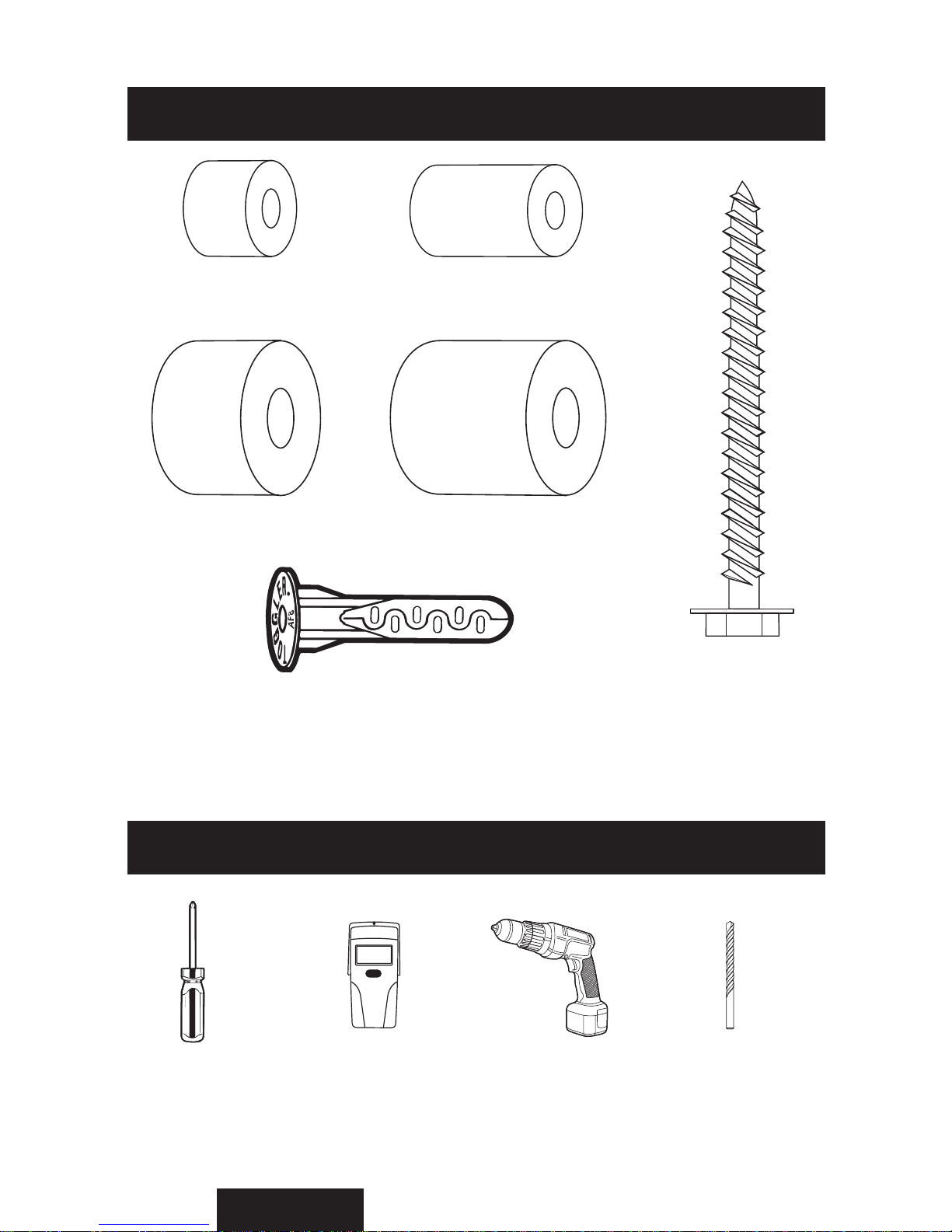
(Q) M6/M8 Short
Spacer, Qty: 4
(P) M6/M8 Long Spacer,
Qty: 4
(D) M4/M5 Short
Spacer, Qty: 4
(E) M4/M5 Long
Spacer, Qty: 4
(U) TOGGLER®brand AF8 ALLIGATOR®Anchor, Qty: 6
(T) #14 X 64mm
Lag Bolt, Qty: 6
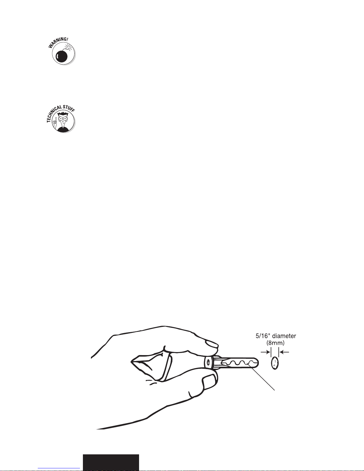
Tools You Will Need
Screwdriver Stud Finder Drill Drill Bit
For wood 5/32" (4mm)
For masonry 5/16" (8mm)

Metric Ratchet
Set
Masking Tape Pencil Tape Measure
Level
Getting ready to hang the TV
Select the location where you want to mount the TV. Clear the area of all furniture and
electronics. You will need some elbow room to mount the TV. You also want to make sure
that your electronic devices are unplugged, covered, and out of way because you are about
to start drilling holes, and that is likely to make dust. You will also need to leave space that
you can use to mount the Monitor Arms (MA) onto the TV.
Your TV may have come with a stand installed. If it did, it is okay to leave it on for
now as long as it does not interfere with the monitor arm installation. If not, you need
to determine the best way to hold or rest your TV safely so you can attach the
monitor arms. Placing the TV face-down can damage the fragile screen or decorative
frame. You may want to get a friend to assist you in holding the TV.If you are
uncertain of the safest way to do this, call the TV manufacturer for advice.
English
Tools You Will Need (continued)
Step 1: Attaching the Adjustable Arms
Your TV owner’s manual generally explains where the mounting location is on the TV.
There are several typical mounting configurations for this size bracket. The mounting hole
distances are measured in millimeters per the VESA (Video Electronics Standards
Association) specifications.

Who is VESA?
The Video Electronics Standards Association is an international nonprofit organization
representing hardware, software, PC, display, and component manufacturers, cable and
telephone companies, and service providers. VESA supports and sets industry-wide
interface standards for the PC, workstation, and computing environments.
Deciding whether you need the Arm Extensions
If you are installing a large TV, you may need to use the supplied Arm Extensions (ME) to
reach the mounting configuration holes on the back of your monitor. To determine if you
need to use the arm extensions, simply hold one of the Monitor Arms (MA) up to the back
of the TV cabinet to see whether the arms can reach the holes. If they do not (as shown in
Figure 1), then you need to attach the extensions to the arms. If the arms reach the holes,
you may skip the next step.
English
Figure 1
Attaching the Arm Extensions
Secure an Arm Extension (ME) to the
top and bottom of each Monitor Arm
(MA) using two of the M8 Nuts (AF)
for each extension as shown in Figure 2.
Use the measurement of the distance
between the screw holes as a guide for
determining how to place the arm
extensions on the monitor arms. Make
sure all four nuts are tightened fully
before moving on.
Figure 2
ME
MA
AF

English
Choosing which screws to use for your TV
You’re probably wondering why so many screws came with this mount. The screw sizes
follow the standards setup by VESA for each mounting configuration.
Most monitors have the mounting holes flush with the back of the monitor. If yours is
like this, you likely need to use short screws. Test several of the screws included in this
kit to find the correct match for the holes in the back of your TV.
Don’t use screws that are too long because they will not fully seat in the holes
and can permanently damage the TV or mounting holes and cause the monitor
to come loose.
Ror S
Selected Screw
DETAILED VIEW
Back
of TV
Figure 3
MA
Attaching the Monitor Arms
After you’ve figured out which screws to use for your TV, attach each Monitor Arm
(MA) to the back of the TV as shown in Figures 3 and 4. Make sure that the arms are
oriented properly, with the adjustment levers facing toward the outer edge of the TV so
that you can reach them later.
Also make sure that each Washer (R for M4 or M5 screws, or S for M6 or M8 screws)
is placed between the screw and the monitor arm. Don’tplace the washers between the
arms and the TV.
Ror S
Selected
Long Screw
MA
Selected
Spacer
English
DETAILED VIEW
Back of TV
Figure 4
Some TVs have mounting holes that are recessed. This kit includes longer mounting
screws and Spacers
(D or E for M4 and M5 screws; P or Q for M6 and M8 screws)
for
such instances. The spacers are used to take up the space in the recessed hole as shown in
Figure 4. The spacer you select must stick out past the back of the TV to ensure secure
mounting. You don’t want the spacer to be loose. The Monitor Arms (MA) need to rest
securely on the spacers.
Test several of the spacers included in this kit to find the
correct match for the recessed holes in the back of your TV.

Step 2: Mounting the Wall Plate
English
Extending the Wall Plate
You need to determine the correct width of the expandable Wall Plate (WP) to fit the
mounting configuration of your TV. To do this, measure the distance from the outside
edges of the Monitor Arms (MA) on the back of your TV using a tape measure. The
wall plate must extend past this measurement and into the “grey zone” (see Figure 5),
but should not extend past the sides of the TV cabinet.
Figure 5
Minimum Wall Plate Width
Maximum Wall Plate Width
Pay attention to how far you extend the wall plate here—the amount of extension
determines whether you use four or six Lag Bolts (T) in the next step of the installation
process! If you extend the Left and Right Extension Plates into, or wider than, the third
expansion slot (see Figure 6), you must use six lag bolts (three studs for wood stud
installations). If you expand the Left and Right Extension Plates into the first or second
expansion slot, you need to use only four lag bolts (two studs for wood stud installations).
Using the socket wrench, loosen and remove the four M8 nuts and washers that
secure the three components of the Wall Plate (WP) together. Extend the Left and
Right Extension Plates to the necessary width for your TV, then secure all three of the
wall bracket parts together again by placing the four M8 washers and nuts over the
screws as shown in Figure 6. Tighten all four M8 nuts fully before attempting to install
the wall plate to the wall.
English
Figure 6
DETAILED VIEW
Before you attach the wall plate to the wall, you
need to insert the M4 x 10mm Security Screws
(AB) into the locking mechanism on each end
of the bracket. Insert them only half-way, so that
the locking arm can still be easily rotated.
AB
12456
3
1
2
4
5
63
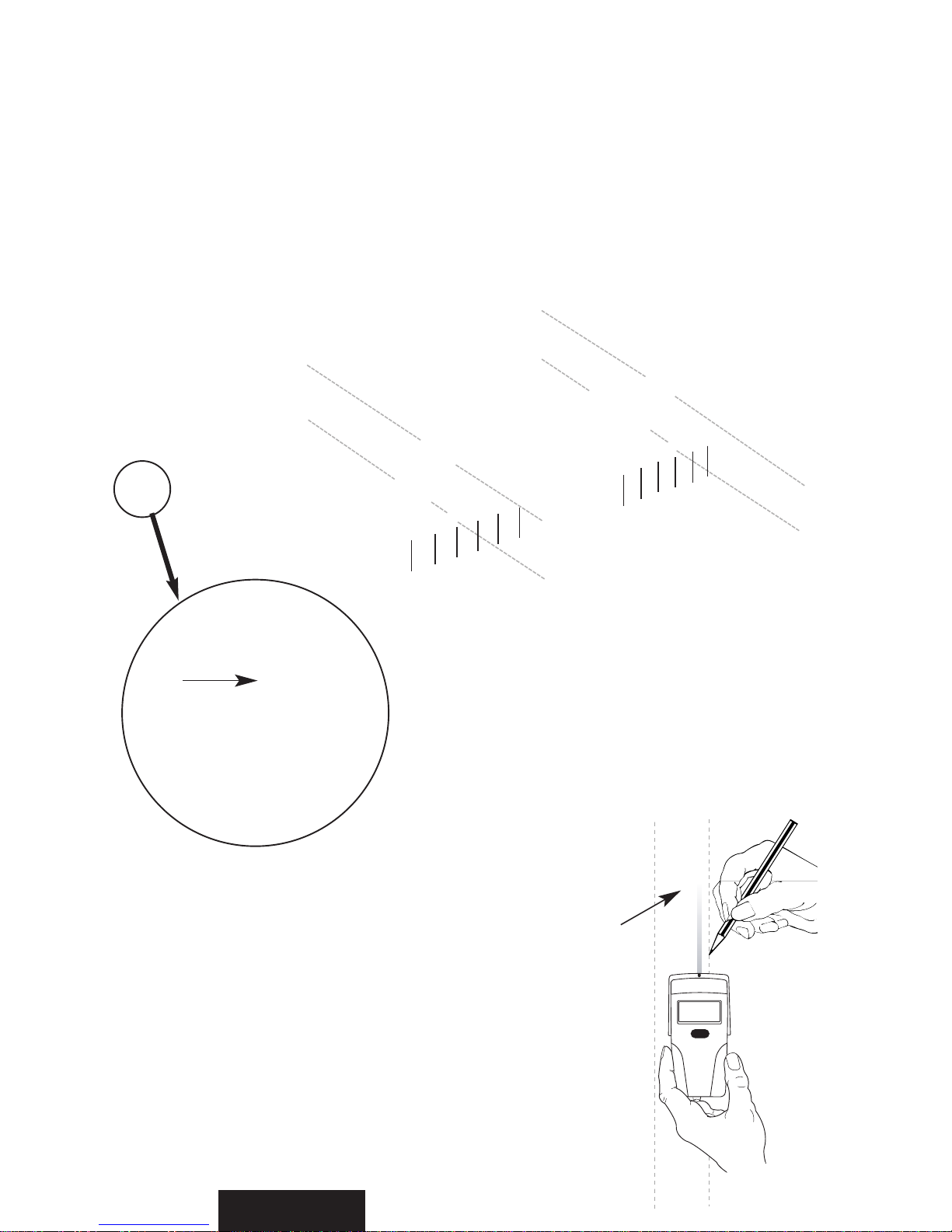
Finding the wood studs to mount to
Using a stud finder,determine the exact location
of the studs to which you want to attach the Wall
Plate (WP). Using an electronic stud finder works
best because it gives you an indication of where
the right and left sides of the stud are.
After you
determine the stud locations, mark the right and
left sides of each stud as shown in Figure 7. These
markings help you determine the center location of
each stud for proper drilling.
Wood
Stud
Figure 7
You need to locate either two studs or three studs, depending on the size of your TV. To
determine whether you need two studs or three, simply refer to how you positioned the
wall plate extensions in the previous step. If you extended the wall plate into or past the
third expansion slot, you need to mount to three studs. If you did not extend your
bracket at all, or extended it less than three slots, you can mount into only two studs.
Next line up the Installation Template (IT) with your pencil markings and tape it into place.
English
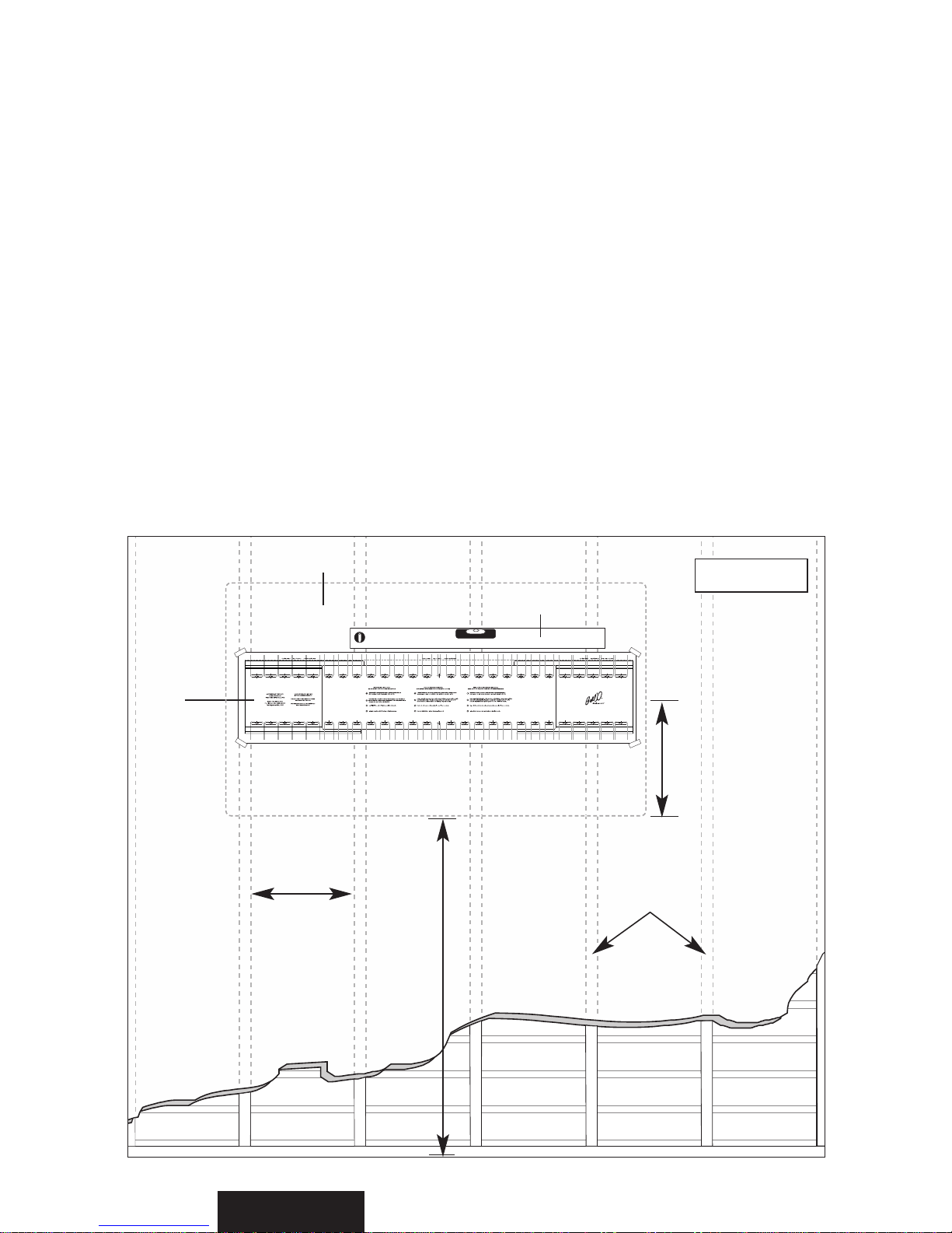
Determining the location of the TV
After the Monitor Arms (MA) have been attached to the TV, measure the distance from
the center of the monitor arms to the top and bottom of the TV to help determine the
desired height of the TV on your wall. The reason that you need to take these
measurements is because many TVs do not have the mounting location centered on the
back of the monitor. To determine the exact height you want to mount the Wall Plate
(WP), use the convenient Installation Template (IT) rather than holding the TV in place
while you do all this measuring. Always make sure to use a level when placing the template.
Measure from the floor up as shown in Figure 8, and using a pencil, make small marks on
the wall to help you determine the desired TV height.
16
Inches
(406mm)
Height to bottom of TV
Distance from
Bottom of TV
to Center of
Monitor Arms
Wood
Studs
IT
Level
Desired Location of TV
Figure 8

You must be careful to accurately drill the holes or else the screws may not line
up with the holes in your Wall Plate (WP).
Line up the installation template with your stud markings to ensure the proper location for
your drill holes. After you have the position selected, tape the template in place securely
on the wall with masking tape so that you don’t damage the wall surface. Use a level to
double-check that the screw holes will line up vertically. Drill all holes 2.5" (64mm) deep
using a 5/32" (or 4mm) size drill bit. Follow the directions on the installation template
carefully. The mount is designed to be installed into two studs if the expansion plates are
in the 1st or 2nd hole position as shown on page 11. If the mount is in the third or wider
expansion slot it must be mounted to three studs.
English
Using the Installation Template
The Installation Template (IT) included in this kit helps you select the correct
positions for drilling the holes for the TV mounting.
Figure 9
When mounting to a wood stud
When you have prepared the holes for mounting the Wall Plate (WP), place the plate
over the holes and screw in the Lag Bolts (T), as shown in Figure 10.
Leave some “wiggle”
room so that you can make any fine adjustments, if necessary.After making sure the wall
mount is level, tighten all of the lag bolts completely.
Tighten the Lag Bolts (T) so that the Wall Plate (WP) is firmly attached to the
wall, but don’t over-tighten! The lag bolts and/or the supporting surface can
become damaged, which greatly reduces their holding ability. Final tightening of
the bolts should always be done by hand, with a Phillips-head screwdriver or
ratchet wrench.
Lines for Locating Stud Markings

English
WP
T
Supporting
Stud
Supporting
Stud
Supporting
Stud
Wall
Figure 10
When mounting to solid concrete, bricks, or cinder block
After you have determined your desired TV location, tape the Installation Template (IT)
in place securely on the wall with masking tape. Use a level to double check that the screw
holes line up vertically, as shown in Figure 11.
Concrete Block Wall
IT
Level
Figure 11
English
Do not drill into mortar joints! Mortar joints are in between the bricks where the
cement is. These joints are typically not strong enough to hold heavy loads. You
need to drill the holes at least one inch from the joint to provide adequate
strength. Use a standard drill with a new masonry drill bit to drill the holes. Do
not use a hammer drill because it can damage the hole or break out the back of
the concrete wall which will not give adequate support to the anchor.
Because drilling an accurate and clean hole is essential to securing your
mount, be sure to use a new drill bit. An old drill bit can not only make
an uneven hole, it can also break out the back of the concrete block
which can diminish the holding ability of the anchor.
Line up the installation template to ensure you’re not going to drill into any mortar joints.
Drill all holes 3" (76mm) deep using a 5/16" (8mm) size drill bit. Follow the directions on the
installation template carefully. The number of screws you will need will depend on how
wide you expand your mount. If you expand into or past the third expansion slot as shown
on page 12 you need to use three Lag Bolts (T), evenly spaced apart on the top and
bottom. If the mount is in the first or second expansion hole, use four lag bolts, evenly
spaced apart on the top and bottom.
This kit includes the TOGGLER®brand ALLIGATOR®Anchors (U) for mounting in
concrete walls, brick, or cinder block. These patented anchors are the finest solid wall
anchors on the market and offer excellent holding ability when properly installed.
After the holes are drilled, remove the template and place four (or six)
ALLIGATOR®Anchors into the concrete wall as shown in Figure 12.
Figure 12
U
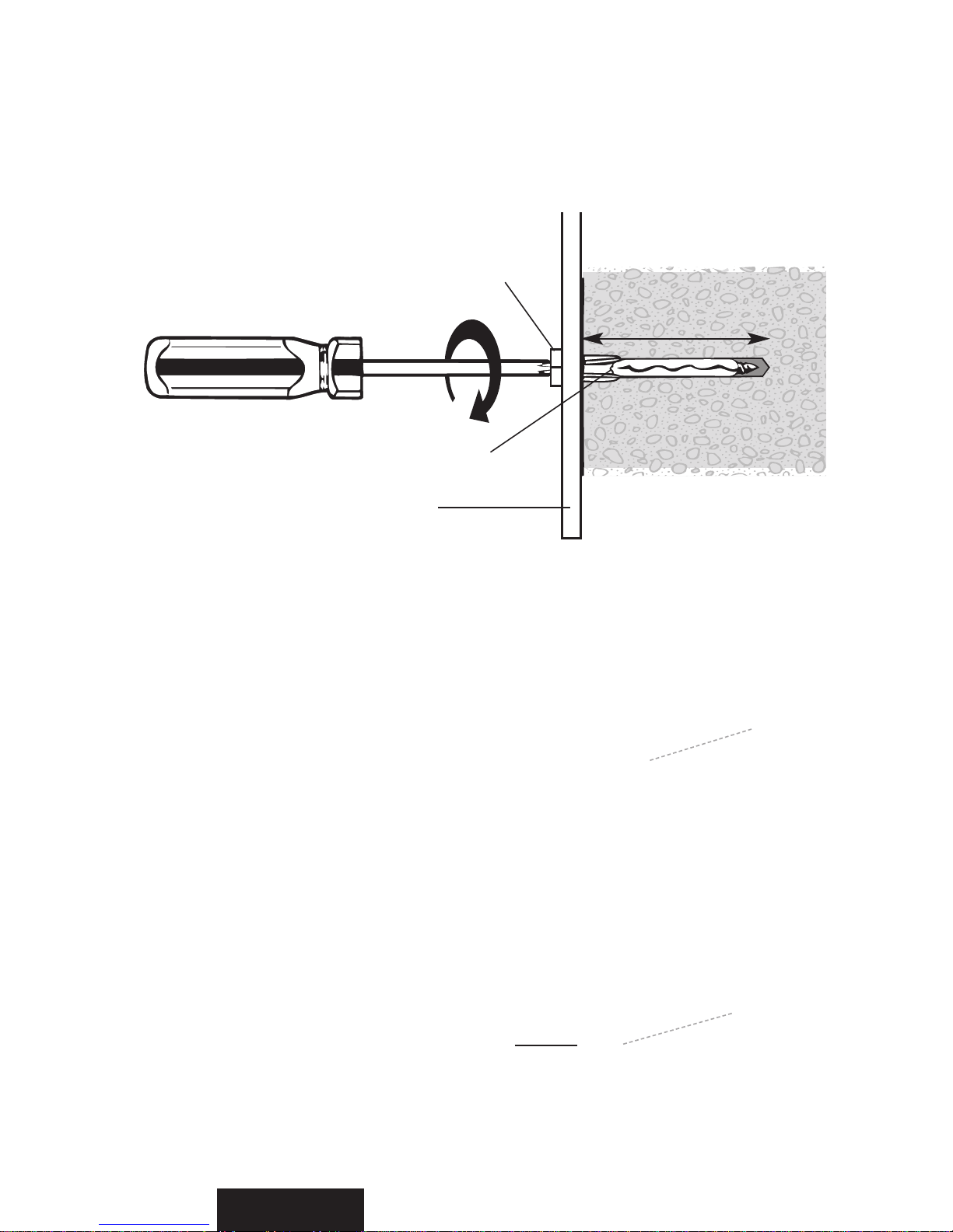
Figure 13
WP
U
T
Concrete
After you have prepared the holes for mounting the Wall Plate (WP), install the wall plate
by inserting the four (or six) Lag Bolts (T) through the mount and into the
ALLIGATOR®Anchors (U)
as shown in Figures 10 and 13. After checking that the
wall mount is level, tighten all lag bolts fully, but be careful not to over-tighten.
English
3" (76mm)
minimum hole depth
Installing the decorative End Covers
Figure 14
WP
EC
Even though your TV hides most
of your wall mount from view,
from the sides you can probably
still see the ends of the bracket.
This kit includes decorative End
Covers (EC) to make your bracket
installation look clean and
finished. To install the end covers,
simply line up the cover with the
end of the bracket, and press into
place. Look for two holes in the
frame of the bracket which the
end cover inserts into, as shown in
Figure 14.

Step 3: Mounting the TV
English
Understanding the locking mechanism
This 8335 TV Wall Mounting Kit For Dummies has a unique feature which enables you
to easily lock the Monitor Arms (MA) onto the Wall Plate (WP) so that your TV cannot
be removed. Before attempting to attach the TV with the monitor arms to the wall bracket, make
sure that the right and left side locking mechanisms are in the unlocked position. Using a
screwdriver, turn the large screw head on the side of the bracket 90° toward the front of
the bracket, as shown in Figure 15. Repeat this procedure on both sides of the bracket.
Large Screw
Head
Locking Bar
Shown Up in
Unlocked Position
To Unlock
Figure 15
If your audio, video, and power cables will not be accessible after you mount
the TV, you need to make those connections now. Before doing this, however,
make sure all TV and component power cords are not plugged into any electri-
cal outlets and your audio and video equipment is turned off. Make sure you
leave enough slack so you can install the mount without any interference.
Don’t forget those wires!

English
Figure 16A
MA
WP
Mounting the TV
DETAILED VIEW
Before you attempt to attach the TV to the wall plate, make sure the adjustable arms
are parallel to the wall (in the 0-degree position). This position is indicated by the
markings on the arms as shown in Figure 16B.
Detailed instructions on how to adjust
the arms can be found on page 20.
When you’re ready to put the TV
with the Monitor Arms (MA) onto
the Wall Plate (WP) assembly, get a
friend or an assistant to help you lift
the TV and guide the monitor arms
onto the wall plate as shown in
Figure 16A.
Markings on the adjustable arm will line up
when in the 0-degree position.
Figure 16B
Make sure the arms are engaged on both the top and bottom rails of the
wall plate!
Locking the arms into place
After the TV with the Monitor Arms (MA) is positioned on the Wall Plate (WP), you
need to lock the arms into place so that the TV cannot inadvertently come off the wall
plate or be removed. To lock the arms, simply turn the large screw head on the side of
both of the bracket’s locking mechanisms 90° toward the wall using a screwdriver as
your assistant holds the TV in place. (See Figure 17.) After you’ve done this, and the
locking mechanism has been engaged, tighten the M4 x 10mm Security Screw (AB)
behind the large lock screw to prevent the locking bar from rotating out of the locked
position. Repeat this procedure on both sides of the bracket. For extra security, in
addition to the security screw, you can also place a padlock through the large holes in
the protruding tabs of the locking mechanism.
Large
Screw Head
AB
Locking Bar
Shown Down in
Locked Position
To
Lock
Figure 17
After the TV is
installed, carefully
try to lift it off to
make sure it is
secure. If it is
correctly secured,
the TV should
not move.
Using the tilting arm feature
After you’ve securely locked the TV with the monitor arms securely onto the wall
plate, you can safely adjust the tilting feature on the arms. The arms can tilt up to 15°
downward or up to 5° upward, depending on your optimum viewing position. Have
your assistant hold the TV steady before you start to adjust the tilt. To adjust the tilt of
your TV, simply reach behind the TV and turn the lever in the center of the arm to
loosen. It works like a ratchet so that you can loosen the lever easily in a very confined
area. To disengage the lever, rotate it away from the monitor arm and reposition as
shown in Figure 19. Push it in again to turn and adjust the arm’s tension as shown in
Figure 18. Repeat this procedure for the lever on the other arm also before attempting
to position the TV.
After the TV is in the desired tilted position, you need to tighten the levers. Turn the
levers clockwise to tighten, pulling out to disengage the rachet mechanism.
English
Table of contents
Other Bell'O TV Mount manuals

Bell'O
Bell'O 7842 User manual

Bell'O
Bell'O SFP-9901HG User manual

Bell'O
Bell'O SFP-9901HG User manual

Bell'O
Bell'O 7610 User manual

Bell'O
Bell'O Triple Play TP4452 User manual

Bell'O
Bell'O 8315 User manual

Bell'O
Bell'O 8220 User manual

Bell'O
Bell'O 7420 User manual

Bell'O
Bell'O 7640 User manual

Bell'O
Bell'O TRIPLE PLAY TP4444 User manual

Bell'O
Bell'O 7410 User manual

Bell'O
Bell'O PP-59 User manual

Bell'O
Bell'O Triple Play NTPC2132G User manual

Bell'O
Bell'O FP-2125 User manual

Bell'O
Bell'O Triple Play TPC2128 User manual

Bell'O
Bell'O Triple Play TPC2128 User manual

Bell'O
Bell'O 8210 User manual

Bell'O
Bell'O 8160 User manual

Bell'O
Bell'O PP-59 User manual

Bell'O
Bell'O FP-4850HG User manual


