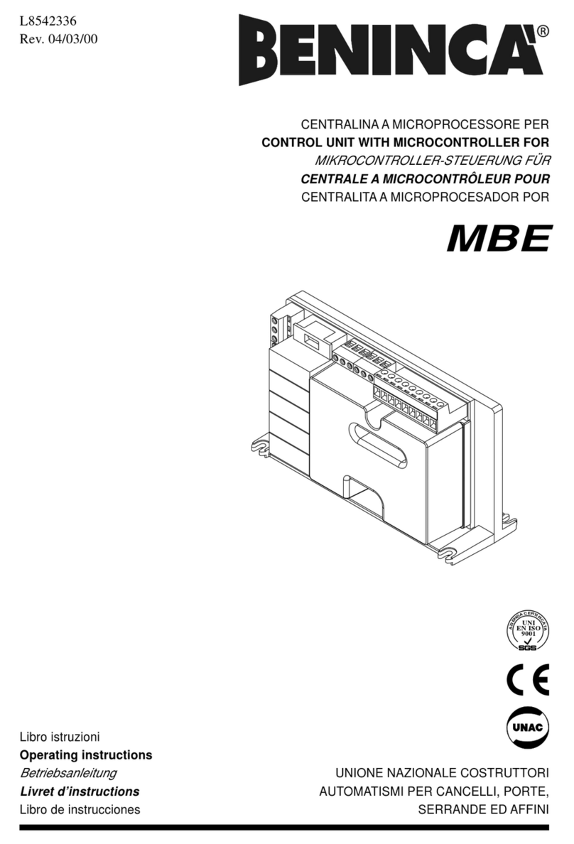
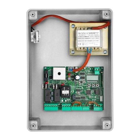
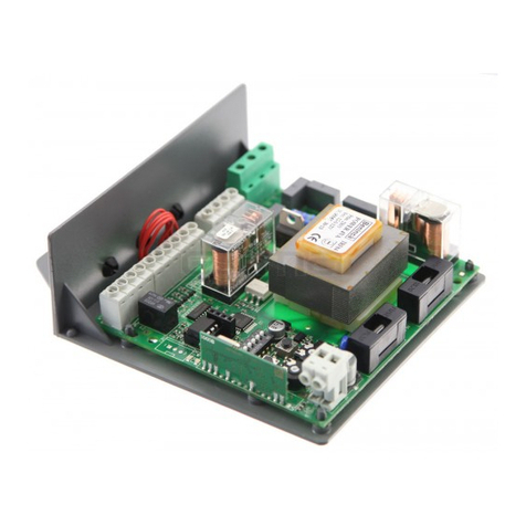
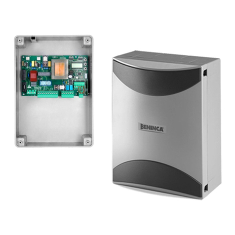
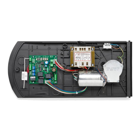
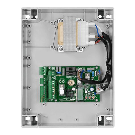
Beninca DREAM User manual

CENTRALE DI COMANDO
CONTROL UNIT
STEUEREINHEIT
CENTRALE DE COMMANDE
CENTRAL DE MANDO
CENTRALKA STEROWANIA
L8542387
Rev. 02/09/01
DREAM
Libro istruzioni
Operating instructions
Betriebsanleitung
Livret d’instructions
Manual de instrucciones
Książeczka z instrukcjami
UNIONE NAZIONALE COSTRUTTORI
AUTOMATISMI PER CANCELLI, PORTE,
SERRANDE ED AFFINI

2
3
3
Dichiarazione CE di conformità Déclaration CE de conformité
EC declaration of conrmity Declaracion CE de conformidad
EG-Konformitatserklarung Deklaracja UE o zgodności
Con la presente dichiariamo che il nostro prodotto
We hereby declare that our product
Hiermit erklaren wir, dass unser Produkt
Nous déclarons par la présente que notre produit
Por la presente declaramos que nuestro producto
Niniejszym oświadczamy że nasz produkt
è conforme alle seguenti disposizioni pertinenti:
complies with the following relevant provisions:
folgenden einschlagigen Bestimmungen entspricht:
correspond aux dispositions pertinentes suivantes:
satisface las disposiciones pertinentes siguientes:
zgodny jest z poniżej wyszczególnionymi rozporządzeniami:
Direttiva sulla compatibilità elettromagnetica (89/336/
CCE, 93/68/CEE)
EMC guidelines (89/336/EEC, 93/68/EEC)
EMV-Richtlinie (89/336/EWG, 93/68/EWG)
Directive EMV (89/336/CCE, 93/68/CEE) (Compatibilité
électromagnétique)
Reglamento de compatibilidad electromagnética (89/336/
MCE, 93/68/MCE)
Wytyczna odnośnie zdolności współdziałania elektromagne-
tycznego (89/336/EWG, 93/68/EWG)
Norme armonizzate applicate in particolare:
Applied harmonized standards, in particular:
Angewendete harmonisierte Normen, insbesondere:
Normes harmonisée utilisées, notamment:
Normas armonizadas utilzadas particularmente:
Normy standard najczęściej stosowane:
EN 55022, EN 61000-3-2, EN 61000-3-3, EN 50082-1
Data/Firma
Direttiva sulla bassa tensione (73/23/CEE, 93/68/CEE)
Low voltage guidelines (73/23/EEC, 93/68/EEC)
Tiefe Spannung Richtlinie (73/23/EWG, 93/68/EWG)
Directive bas voltage (73/23/CEE, 93/68/CEE)
Reglamento de bajo Voltaje (73/23/MCE, 93/68/MCE)
Wytyczna odnośnie niskiego napięcia (73/23/EWG, 93/
68/EWG)
Norme armonizzate applicate in particolare:
Applied harmonized standards, in particular:
Angewendete harmonisierte Normen, insbesondere:
Normes harmonisée utilisées, notamment:
Normas armonizadas utilzadas particularmente:
Normy standard najczęściej stosowane:
EN 60204-1, EN 60335-1
Data/Firma
Automatismi Benincà SpA
Via Capitello, 45
36066 Sandrigo (VI)
ITALIA

2
3
J1
J1 DAS
Close
DAS 8K2
J1 DAS
Open
DAS N.C.
PHOT
RADIO
ON
SW2
1 4
P1
F0,200A
230V:F5A
115V:F10A
PGM
DL1
F1
F2
COM
C
M
NL
L N 3 4 5 6 7 8 9 10 11
10 11
12
14
15
13
N.O.
24Vac
100mA max
PP PHOT
SHIELD
ANT
ANT
8k2
DAS
Lamp 230Vac*
40W MAx
*DREAM 115: 115Vac-40Wmax

4
5
Centrale di comando DREAM
La centrale elettronica DREAM può essere utilizzata per il controllo di 1 motore con potenza non superiore
a 500W.
AVVERTENZE GENERALI
a) L’installazione elettrica e la logica di funzionamento devono essere in accordo con le normative vigenti.
b) I conduttori alimentati con tensioni diverse, devono essere sicamente separati, oppure devono essere
adeguatamente isolati con isolamento supplementare di almeno 1 mm.
c) I conduttori devono essere vincolati da un ssaggio supplementare in prossimità dei morsetti.
d) Ricontrollare tutti i collegamenti fatti prima di dare tensione.
e) Controllare che le impostazioni dei Dip-Switch siano quelle volute.
f) Gli ingressi N.C. non utilizzati devono essere ponticellati.
FUNZIONI INGRESSI/USCITE
N° Morsetti Funzione Descrizione
1-2 Alimentazione DREAM: Ingresso 230Vac 50Hz (1-Fase/2-Neutro)
Versione DREAM115: Ingresso 115vac 60Hz (1-Fase/2-Neutro)
3-4-5 Motore Collegamento al motore (3-marcia/4-Com/5-marcia)
3-5 Condensatore Collegamento condensatore
6-7 24 Vac Uscita alimentazione accessori 24Vac/100 mA max.
8-9 PP Ingresso pulsante passo-passo apre>stop>chiude>stop.
Contatto N.O.
10-11 PHOT/COSTA
Ingresso per fotocellula o costa sensibile, attivo solo in fase di
chiusura.
Utilizzato come ingresso fotocelulla:
Jumper J4 Aperto. Dip-Switch 3 OFF.
Utilizzato come ingresso costa sensibile:
Costa resistiva: Jumper “J4” chiuso. Dip-Switch 3 ON.
Costa meccanica: Jumper “J4” aperto. Dip-Switch 3 ON.
12-13 TIMER/II°ch Uscita (contatto N.O.) congurabile come secondo canale radio o
temporizzato. Vedi descrizione DIP 4.
14-15 Antenna Collegamento antenna scheda radioricevente incorporata
(14-segnale/15-schermo).
MD1 RADIO Ricevitore radio bicanale incorporato. Vedi DIP 1
FUNZIONE DIP-SWITCH
DIP 1 “CVAR” Abilita o disabilita i trasmettitori a codice sso.
On: Sono abilitati solo i trasmettitori a codice variabile (massimo 14 codici).
Off: Sono abilitati sia i trasmettitori a codice variabile sia i trasmettitori a codice sso (massimo 14
codici).
DIP 2 Vedi paragrafo “Apprendimento corsa”
DIP 3 “PHOT/COSTA” Seleziona la modalità di funzionamento dell’ingresso 10-11.
On: L’apertura del contatto in fase di chiusura provoca l’arresto del movimento (STOP).
Il comando che segue l’arresto sarà sempre un comando APRE.
Off: L’apertura del contatto provoca l’inversione no alla totale apertura. A questo punto inizia
il conteggio del tempo di lavoro rimanente e dell’eventuale tempo di chiusura automatica, al
termine del conteggio la centrale comanda una nuova manovra di chiusura.
DIP 4 “TIMER” Seleziona la modalità di funzionamento dell’uscita TIMER/II°ch.
On: Contatto pulito NO controllato dal secondo canale radio della ricevente incorporata. Il tempo
di commutazione è regolabile tramite il trimmer P1 (timer) da 1s a 200s.
Off: Contatto pulito NO per il controllo di luci di servizio, segnalazione, ecc. La commutazione
avviene simultaneamente ad ogni movimento della porta. Il tempo di commutazione è regolabile
tramite il trimmer P1 (timer) da 1s a 200s.

4
5
APPRENDIMENTO CORSA
L’apprendimento della corsa (tempo di lavoro) e del tempo di richiusura automatica (TCA), si effettua
seguendo questa procedura:
1 - Portare il DIP2 in ON.
Se si desidera la richiusura automatica (TCA) portare il DIP4 in ON.
Se non si desidera la richiusura automatica, portare il DIP4 in OFF.
2 - Dare un comando PP (con pulsante o trasmettitore) e attendere la completa apertura.
3 - Con la porta aperta dare un comando PP:
a) Se il DIP4 è in ON inizia il conteggio del tempo TCA. Attendere il tempo TCA desiderato, quindi dare
un nuovo comando PP, la porta si muove in chiusura.
b) Se il DIP4 è OFF si può dare subito un nuovo comando PP, la porta si muove in chiusura.
4 - Inizia il conteggio del tempo di lavoro. Attendere la chiusura della porta e l’arresto, attendere qualche
secondo come margine di manovra quindi dare un nuovo comando PP che memorizza il tempo di
lavoro.
5 - Riportare il DIP2 in OFF, riportare il DIP 4 alla posizione iniziale.
CONFIGURAZIONE RICEVITORE INCORPORATO
La centrale è dotata di un modulo radio incorporato per la ricezione di telecomandi sia a codice sso che a
codice variabile (vedi funzioni dip-switch 1), con frequenza di 433.92MHz.
Per utilizzare un telecomando è prima necessario apprenderlo, la procedura di memorizzazione è illustrata
di seguito, il dispositivo è in grado di memorizzare no a 14 codici diversi.
Memorizzazione di un nuovo trasmettitore con attivazione funzione P.P.
- Premere 1 volta il pulsante PGM per 2s, il LED DL1 inizia a lampeggiare velocemente.
- Premere entro 10s il pulsante del trasmettitore che si desidera memorizzare con funzione P.P.
Dopo la memorizzazione del trasmettitore la ricevente esce dalla fase di programmazione.
Memorizzazione di un nuovo trasmettitore con attivazione uscita 2° canale radio (DIP4:ON)
- Premere 2 volte il pulsante PGM, ogni volta per almeno 2 secondi, il led DL1 si accende a luce ssa.
- Premere entro 10s il pulsante del trasmettitore che si desidera memorizzare con funzione 2° canale
radio.
Dopo la memorizzazione del trasmettitore la ricevente esce dalla fase di programmazione.
Cancellazione di tutti i trasmettitori dalla memoria
- Togliere alimentazione di rete, premere il pulsante PGM e mantenendolo premuto ridare alimentazione di
rete.
- Mantenere premuto il pulsante PGM per 5s, il led DL1 si accende a luce ssa.
- Rilasciare il pulsante PGM, la memoria è stata cancellata.
NOTA:
Per motivi di sicurezza, non è possibile memorizzare trasmettitori durante le fasi apertura/chiusura del
motore.
Se nella fase di memorizzazione dei trasmettitori, successivamente alla pressione del pulsante del
trasmettitore, il LED DL1 emette un lampeggio lungo e si spegne, signica che la memoria della ricevente
è completa (il trasmettitore pertanto non viene memorizzato) o che il trasmettitore utilizzato non è
compatibile.

6
7
DREAM Control Unit
The DREAM control unit can be used to control 1 motor with power not exceeding 500W.
GENERAL WARNINGS
a) The wire connections and the operating logic should be in compliance with regulations in force.
b) The cables featuring different voltage should be physically separated, or adequately insulated by an
additional insulation of at least 1 mm.
c) The cables should be further fastened in proximity to the terminals.
d) Check all connections before powering the unit.
e) Check that setting of the Dip-Switches are the required ones.
f) Normally Closed inputs which are not in use should be short-circuited.
INPUTS/OUTPUTS
Terminal no. Function Description
1-2 Power Supply DREAM: Input, 230Vac 50Hz (1-Phase/2-Neutral)
Model DREAM115: Input 115vac 60Hz (1-Phase/2-Neutral)
3-4-5 Motor Connection to motor (3-marcia/4-Com/5-marcia)
3-5 Capacitor Connection to capacitor
6-7 24 Vac Output, power supply of accessories, 24Vac/100 mA max.
8-9 Step-by-Step Input, step-by-step push button open>stop>close>stop.
N.O. contact
10-11 PHOT/SAFETY
EDGE
Input, photocell or safety edge.
It is activated in the closing phase only.
It is used as photocell input:
Jumper J4 Open. Dip-Switch 3 OFF.
Used as input for safety edge:
Safety edge of the resistive type: Jumper “J4” closed. Dip-Switch
3 OFF.
Safety edge of the mechanical type: Jumper “J4” open. Dip-
Switch 3 OFF.
12-13 TIMER/2nd ch. Output (N.O. contact). It can be set for second radio channel or
timed. See description of DIP 4.
14-15 Antenna Connection of antenna with built-in radio receiver module
(14-signal/15-display).
MD1 RADIO Built-in two-channel radio receiver. See DIP 1
FUNCTIONS OF DIP-SWITCHES
DIP 1 “CVAR” – Fixed code transmitters are enabled or disabled.
On: Only variable-code transmitters are enabled (14 codes maximum).
Off: Both variable code transmitters and xed code transmitters are enabled (14 codes
maximum).
DIP 2 See paragraph “Learning of stroke”
DIP 3 “PHOT/SAFETY EDGE” – Selects the operating mode of input 10-11.
On: When the contact is opened in the closing phase the gate/door stops (STOP).
The control following the stop will always be an OPEN control signal.
Off: The opening of the contact causes the movement reversion until the gate is totally opened.
At this point, the counting of the remaining operating time and of the possible automatic closure
starts. At end of counting, the control unit starts a new closing operation.

6
7
DIP 4 “TIMER”- The operating mode of TIMER/II°ch output is selected.
On: Normally Open, free contact. This is controlled by the second radio channel of the built-in
receiver. The switching time is adjustable through the trimmer P1 (timer) from 1 to 200s.
Off: Normally Open, free contact. This is to control service lights, indicator lamps, etc. The
contact switches every time the door moves. The switching time is adjustable through the trimmer
P1 (timer) from 1 to 200s.
STROKE LEARNING
The learning of the stroke (operating time) and of the automatic re-closure time (TCA) is carried out through
the following procedure:
1 - Move DIP2 to ON.
To obtain an automatic re-closure (TCA) move DIP4 to ON.
If the automatic re-closure is not required, move DIP4 to OFF.
2 - Send a Step-by- Step control (through the push-button or the transmitter) and wait that the door is
completely open.
3 - With open door, send a Step-by-Step control:
a) If the DIP4 is to ON, the TCA time counting starts. Wait that the desired TCA time has elapsed, then
send a new Step-by-Step control and the door comes to a closure.
b) If the DIP4 is OFF, a new Step-by-Step control can be sent immediately, and the door comes to a
closure.
4 - The counting of the operating time starts. Wait that the door is completely closed and the movement
comes to a stop, wait some seconds, then send a new Step-by-Step control signal to store the operating
time in memory.
5 - Move DIP2 to OFF again, move DIP 4 to the initial position again.
CONFIGURATION OF THE BUILT-IN RECEIVER
The control unit is tted with a built-in radio module for receiving remote controls both with xed codes
and variable codes (see dip-switch 1 functions), with a frequency of 433.92MHz.
For a transmitter to be used, the module rst has to self-learn its code. The memorise procedure is
illustrated below, the module can memorise up to 14 different codes.
Memorising a new transmitter by activating the P.P. function
- Press the PGM button once for 2sec and the LED DL1 starts ashing rapidly.
- Press the transmitter button within 10 sec to memorise with the P.P. (Step-by-step) function.
After the transmitter has been stored in memory, the receiver exits the programming phase.
To memorise a new transmitter code with activation of 2nd radio channel output (DIP4:ON)
- Press push-button PGM twice, each time for at least 2 seconds, LED DL1 switches on with xed light.
- Within the following 10 seconds, press the transmitter push-button to be memorised with 2nd radio
channel function.
After the transmitter has been stored in memory, the receiver exits the programming phase.
Cancelling all transmitters from the memory
- Cut-off the mains power supply, press the PGM push-button and power the system again, still keeping
the button pressed.
- Keep the PGM button pressed for 5 sec, the LED DL1 switches on with xed light.
- Release the PGM button, the memory is now erased.
N.B.: For safety reasons, transmitters cannot be memorised during the open/close cycles of the motor.
During the memorisation phase of the transmitter codes, if, after pressing the push-button of the
transmitter, DL1 LED lights up with a long ash and then switches off, this means that the receiver is full
(therefore, the code is not stored in memory) or the transmitter used is not compatible.
8
9
Steuereinheit DREAM
Die elektronische Einheit DREAM kann zur Kontrolle von 1 Motor mit einer maximalen Leistung von 500W
verwendet werden.
ALLGEMEINE HINWEISE
a) Die elektrische Installation und die Betriebslogik müssen den geltenden Vorschriften entsprechen.
b) Die Leiter die mit unterschiedlichen Spannungen gespeist werden, müssen physisch getrennt oder
sachgerecht mit einer zusätzlichen Isolierung von mindestens 1 mm isoliert werden.
c) Die Leiter müssen in der Nähe der Klemmen zusätzlich befestigt werden.
d) Alle Anschlüsse nochmals prüfen, bevor die Zentrale mit Strom versorgt wird.
e) Kontrollieren, ob die Dip-Schalter richtig positioniert sind.
f) Die nicht verwendeten N.C. Eingänge müssen überbrückt werden.
FUNKTIONEN EINGÄNGE/AUSGÄNGE
Klemmen Funktion Beschreibung
1-2 Speisung DREAM: Eingang 230Vac 50Hz (1-Phase/2-Nulleiter)
Ausführung DREAM115: Eingang 115vac 60Hz (1-Phase/2-Nulleiter)
3-4-5 Motor Anschluss an den Motor (3-Betrieb/4-Com/5-Betrieb)
3-5 Kondensator Anschluss Kondensator
6-7 24 Vac Ausgang Speisung Zubehör 24Vac/100 A max.
8-9 PP Eingang Taste Schritt-Schritt Öffnen>stop>schließen>stop.
Kontakt N.O.
10-11 PHOT/FLANKE
Eingang für Fotozelle oder Näherungsanke nur beim Schließen aktiv.
Verwendung als Fotozellen-Eingang:
Jumper J4 geöffnet. Dip-Schalter 3 OFF.
Verwendung als Eingang der Näherungsanke:
Widerstandsfähige Flanke: Jumper “J4” geschlossen. Dip-Schalter 3
ON.
Mechanische Flanke: Jumper “J4” geöffnet. Dip-Schalter 3 ON.
12-13 TIMER/II°ch Ausgang (Kontakt N.O.) als zweiter Funkkanal oder zeitgesteuert kon-
gurierbar. Siehe Beschreibung DIP 4.
14-15 Antenne Anschluss Antenne Karte eingebauter Funkempfänger
(14-Signal/15-Schirm).
MD1 FUNK Eingebauter Zweikanal-Funkempfänger Siehe DIP 1.
DIP-SCHALTER-FUNKTION
DIP 1 “CVAR” Aktiviert oder deaktiviert die Sendegeräte mit festem Code.
On: Alle Sendegeräte mit variablem Code sind aktiviert (maximal 14 Codes)
Off: Alle Sendegeräte mit variablem Code und festem Code sind aktiviert (maximal 14 Codes)
DIP 2 Siehe Paragraph “Hub lernen”.
DIP 3 “FLANKE” Wählt die Betriebsweise des Eingangs 10-11.
On: Das Öffnen des Kontakts beim Schließen hat das Anhalten der Bewegung zur Folge (STOP).
Die Steuerung die das Anhalten bewirkt, ist immer eine Steuerung ÖFFNEN.
Off: Das Öffnen des Kontakts hat das Umschalten bis zur vollkommenen Öffnung zur Folge.
Nun beginnt die restliche Zeit des Betriebs und ggf. die Zeit des automatischen Schließvorgangs
abzulaufen. Nach abgelaufener Zeit steuert die Zentrale einen neuen Schließvorgang.

8
9
DIP 4 “TIMER” Wählt die Betriebsweise des Ausgangs TIMER/II°ch.
On: Reiner Kontakt N.O. durch den 2. Funkkanal des eingebauten Empfängers gesteuert. Die
Umschaltzeit ist über den Trimmer P1 (Timer) zwischen 1s und 200s einstellbar.
Off: Reiner Kontakt N.O. zur Steuerung der Betriebs-, Meldeleuchten usw. Die Umschaltung
erfolgt gleichzeitig mit jeder Türbewegung. Die Umschaltzeit ist über den Trimmer P1 (Timer)
zwischen 1s und 200s einstellbar.
HUB LERNEN
Um den Hub (Betriebszeit) und die Zeit für den automatischen Schließvorgang (TCA) zu lernen,
folgendermaßen vorgehen:
1 - DIP2 auf ON schalten.
Wird der automatische Schließvorgang (TCA) gewünscht, DIP4 auf ON schalten.
Wird der automatische Schließvorgang (TCA) nicht gewünscht, DIP4 auf OFF schalten.
2 - Den Befehl PP geben (über die Taste oder das Sendegerät) und warten bis der Schließvorgang beendet
ist.
3 - Bei offener Tür den Befehl PP geben:
a) Wenn DIP4 auf ON geschaltet ist, beginnt die Zeit TCA abzulaufen. Wenn die gewünschte Zeit TCA
abgelaufen ist, nochmals den Befehl PP geben. Die Tür beginnt sich zu schließen.
b) Wenn DIP4 auf OFF geschaltet ist, sofort wieder den Befehl PP geben. Die Tür beginnt sich zu
schließen.
4 - Die Betriebszeit beginnt abzulaufen. Warten bis die Tür geschlossen und der Vorgang gestoppt ist. Dann
einige Sekunden warten (Bewegungsmarge) und erneut den Befehl PP geben, der nun die Betriebszeit
speichert.
5 - DIP2 wieder auf OFF und DIP4 auf die Ausgangsposition schalten.
KONFIGURATION DES EINGEBAUTEN EMPFÄNGERS
Die Zentrale ist mit einem eingebauten Funkmodul für den Empfang von Fernbedienungen mit xem oder
variablem Code (siehe Funktionen Dip-Switch 1), bei einer Frequenz von 433.92MHz ausgestattet.
Um eine Fernbedienung benutzen zu können, muss diese zunächst programmiert werden.
Das Speicherverfahren wird nachstehend beschrieben. Die Vorrichtung kann bis zu 14 verschiedene Codes
speichern.
Speichern eines neuen Senders mit Aktivierung der Funktion P.P. (Schrittschaltung)
- 1 Mal die Taste PGM 2s lang drücken, die Leuchte DL1 blinkt schnell .
- Innerhalb von 10s die Taste des Senders drücken, die mit der Funktion P.P. belegt werden soll.
Nachdem das Sendegerät gespeichert worden ist, beendet der Empfänger die Programmierungsphase.
Speicherung eines neuen Sendegeräts und Aktivierung des Ausgangs 2. Funkkanal (DIP4: ON)
- Die Taste PGM 2 Mal jeweils 2 Sekunden lang drücken; die Leuchte DL1 leuchtet fest.
- Innerhalb von 10s Sekunden die Taste des Sendegeräts drücken, die mit der Funktion 2. Funkkanal
gespeichert werden soll.
Nachdem das Sendegerät gespeichert worden ist, beendet der Empfänger die Programmierungsphase.
Löschen aller Sender aus dem Speicher
- Das Gerät stromlos machen, die Taste PGM drücken und gedrückt halten und gleichzeitig wieder Strom
geben.
- Die Taste PGM 5s Sekunden lang gedrückt halten; die Leuchte DL1 leuchtet fest.
- Die Taste PGM loslassen, der Speicher ist gelöscht.
NB:
Aus Sicherheitsgründen können die Sender nicht während des Öffnens/Schließens des Motors gespeichert
werden.
Wenn man die Speicherungsprozedur der Sendegeräte durch Drücken der Taste am Sendegerät abruft und
die Leuchte DL1 langsam blinkt und dann erlischt, bedeutet dies, dass der Speicher des Empfängers voll ist
(das Sendegeräte wird nicht gespeichert) oder dass das verwendete Sendegerät nicht kompatibel ist.

10
11
Centrale de commande DREAM
La centrale électronique DREAM peut être utilisée pour le contrôle de 1 moteur ne dépassant pas la
puissance de 500W.
AVERTISSEMENTS GENERAUX
a) L’installation électrique et la logique de fonctionnement doivent être conformes aux normes en vigueur.
b) Les conducteurs alimentés avec des tensions différentes, doivent être séparés physiquement, ou
dûment isolés avec une isolation supplémentaire d’au moins 1 mm.
c) Les conducteurs doivent être liés par un xage supplémentaire en proximité des bornes.
d) Avant de remettre sous tension, contrôler à nouveau tous les raccordements faits.
e) Contrôler que les réglages des Dip-Switch soient conformes à vos nécessités.
f) Les entrées N.F. non utilisées doivent être pontées.
FONCTIONS ENTREES/SORTIES
N° Serre-joints Fonctions Description
1-2 Alimentation DREAM: Entrée 230Vac 50Hz (1-Phase/2-Neutre)
Version DREAM115: Entrée 115vac 60Hz (1-Phase/2-Neutre)
3-4-5 Moteur Branchement au moteur (3-marche/4-Com/5-marche)
3-5 Condensateur Branchement condensateur
6-7 24 Vac Sortie alimentation accessoires 24Vac/100 mA max.
8-9 PP Entrée touche pas à pas ouvre>stop>ferme>stop.
Contact N.O.
10-11 PHOT/BARRE
Enterée pour photocellule ou bord sensible de sécurité. Activé
uniquement en phase de fermeture.
Utilisé comme entrée photocellule:
Jumper J4 Ouvert. Dip-Switch 3 OFF.
Utilisé comme entrée bord sensible de sécurité:
Barre pneumatique: Jumper “J4” fermé. Dip-Switch 3 ON.
Barre mécanique: Jumper “J4” ouvert. Dip-Switch 3 ON.
12-13 MINUTEUR/
II°ch
Sortie (contact N.O.) paramétrable en tant que deuxième chaîne
radio ou temporisé. Voir description DIP 4.
14-15 Antenne Branchement antenne carte radio réceptrice intégrée
(14-signal/15-écran).
MD1 RADIO Récepteur radio bicanal intégré. Voir DIP 1
FONCTION COMMUTATEUR DIP
DIP 1 “CVAR” Valide ou invalide les transmetteurs à code xe.
On: Seul les transmetteurs à code variable sont validés (14 codes maximum).
Off: Soit les transmetteurs à code variable et les transmetteurs à code xe sont validés (14 codes
maximum).
DIP 2 Voir paragraphe “Apprentissage Course”
DIP 3 “PHOT/BARRE” La modalité de fonctionnement de l’entrée 10-11 peut être sélectionnée.
On: L’ouverture du contact en phase de fermeture cause l’arrêt du movement (STOP).
La commande suivant l’arrêt sera toujeours une commande OUVRE.
Off: L’ouverture du contact cause l’inversion du movement jusqu’à l’ouverture totale. Le comptage
du temps de travail restant et du possible temps de fermeture automatique commence. A la n du
comptage, la centrale commande une nouvelle manoeuvre de fermeture.

10
11
DIP 4 “MINUTEUR” Sélectionnez le mode de fonctionnement de la sortie MINUTEUR/II°ch.
On: Contact propre NO contrôlé par la deuxième chaîne du récepteur intégré. Le temps de
commutation peut être réglé moyennant le trimmer P1 (minuteur) de 1s à 200s.
Off: Contact propre NO pour contrôler les lumières de service, signalisation, etc. La commutation
a lieu simultanément à chaque mouvement de la porte. Le temps de commutation peut être réglé
moyennant le trimmer P1 (minuteur) de 1s à 200s.
APPRENTISSAGE DE LA COURSE
L’apprentissage de la course (temps de travail) et du temps de refermeture automatique (TCA), s’effectue
selon la procédure suivante:
1 - Portez le DIP2 sur ON.
Si vous désirez la refermeture automatique (TCA) portez le DIP4 sur ON.
Si vous ne désirez pas la refermeture automatique, portez le DIP4 sur OFF.
2 - Donnez une commande PP (avec bouton pressoir ou transmetteur) et attendez la fermeture complète.
3 - Avec la porte ouverte donnez une commande PP:
a) Si le DIP4 est sur ON le compte du temps TCA commence. Attendez le temps TCA désiré et donnez
une nouvelle commande PP, la porte bouge en fermeture.
b) Si le DIP4 est OFF il est possible de donner immédiatement une nouvelle commande PP, la porte
bouge en fermeture.
4 - Le compte du temps de travail commence. Attendez la fermeture de la porte et l’arrt, après quelques
secondes pour le marge de manœuvre donnez une nouvelle commande PP et mémorisez le temps de
travail.
5 - Ramenez le DIP2 sur OFF et le DIP 4 sur la position initiale.
CONFIGURATION DU RECEPTEUR INTEGRE’
La logique de commande est munie d’un module radio incorporé pour la réception d’émetteurs aussi bien à
code xe qu’à code variable (voir fonctions dip-switch 1), à la fréquence de 433,92 MHz.
Pour utiliser un émetteur, il faut d’abord l’enregistrer, la procédure de mémorisation est illustrée ci-après, le
dispositif est en mesure de mémoriser jusqu’à 14 codes différents.
Mémorisation d’un nouvel émetteur avec activation fonction P.P.
- Presser 1 fois la touche PGM pendant 2 s,
la LED DL1 commence à clignoter rapidement
.
- Presser dans les 10 s la touche de l’émetteur que l’on souhaite mémoriser avec fonction P.P.
Après la mémorisation du transmetteur le récepteur sort de la phase de programmation.
Mémorisation d’un nouveau transmetteur avec activation sortie 2e canal radio (DIP4:ON)
- Appuyez 2 fois sur la touche PGM, chaque fois au moins pendant 2 secondes, la LED DL1 s’allume à lumière
xe.
- Appuyez dans l’espace de 10s la touche du transmetteur que vous désirez mémoriser avec fonction 2e canal
radio.
Après la mémorisation du transmetteur le récepteur sort de la phase de programmation.
Effacement de tous les émetteurs de la mémoire
- Coupez l’alimentation, appuyez sur la touche PGM, et toujours en gardant la touche appuyée et
rétablissez l’alimentation.
- Maintenez appuyée la touche PGM pendant 5s,
la LED DL1 s’allume à lumière xe.
- Relâchez la touche PGM, la mémoire a été effacée.
N.B.:
Pour des raisons de sécurité, il n’est pas possible de mémoriser des émetteurs durant les phases
d’ouverture et de fermeture.
Si durant la phase de mémorisation des transmetteurs, la LED DL1 après un long clignotement s’éteint ,
cela signie que la mémoire du récepteur est complète (donc le transmetteur n’est mémorisé) ou bien que
le transmetteur utilisé n’est pas compatible.

12
13
Central de control DREAM
La central electrónica DREAM se puede utilizar para controlar 1 motor con potencia no mayor que 500W.
ADVERTENCIAS GENERALES
a) La instalación eléctrica y la lógica de funcionamiento deben cumplir las normas vigentes.
b) Los conductores alimentados con tensiones distintas deben estar físicamente separados, o bien deben
estar adecuadamente aislados con aislamiento suplementario de por lo menos 1 mm.
c) Los conductores deben estar vinculados por una jación suplementaria cerca de los bornes.
d) Comprobar todas las conexiones efectuadas antes de dar la tensión.
e) Comprobar que las conguraciones de los Dip-Switch sean las deseadas.
f) Las entradas N.C. no utilizadas deben estar puenteadas.
FUNCIONES ENTRADAS/SALIDAS
N° Bornes Función Descripción
1-2 Alimentación DREAM: Entrada 230Vac 50Hz (1-Fase/2-Neutro)
Versión DREAM115: Entrada 115vac 60Hz (1-Fase/2-Neutro)
3-4-5 Motor Conexión al motor (3-marcha/4-Com/5-marcha)
3-5 Condensador Conexión condensador
6-7 24 Vca Salida alimentación accesorios 24Vac/100 mA máx.
8-9 PP Entrada botón paso-paso abre>stop>cierra>stop.
Contacto N.A.
10-11 PHOT/BORDE
Entrada para fotocélula o borde sensible, activa sólo en la fase de
cierre.
Utilizada como entrada fotocélula:
Puente J4 Abierto. Dip-Switch 3 OFF.
Utilizada como entrada borde sensible:
Borde resistivo: Puente J4 Cerrado Dip-Switch 3 ON.
Borde mecánico: Puente J4 Abierto. Dip-Switch 3 ON.
12-13 TIMER/II°ch Salida (contacto N.A.) congurables como segundo canal radio o
temporizado. Ver descripción DIP 4.
14-15 Antena Conexión antena tarjeta radiorreceptor incorporado
(14-señal/15-pantalla).
MD1 RADIO Receptor radio bicanal incorporado. Ver DIP 1
FUNCIÓN DIP-SWITCH
DIP 1 “CVAR” Habilita o inhabilita los transmisores de código jo.
On: Están habilitados sólo los transmisores de código variable (máximo 14 códigos).
Off: Están habilitados tanto los transmisores de código variable como los transmisores de código
jo (máximo 14 códigos).
DIP 2 Ver apartado “Aprendizaje carrera”
DIP 3 “PHOT/BORDE”
“PHOT/BORDE” Selecciona la modalidad de funcionamiento de la entrada 10-11.
On: La apertura del contacto en la fase de cierre causa la parada del movimiento (STOP).
El mando después de la parada será siempre un mando ABRE.
Off: La apertura del contacto provoca la inversión de la dirección de marcha hasta la apertura
total. Ahora empieza el conteo del tiempo de trabajo restante y del eventual tiempo de cierre
automático, al nal de la cuenta la central manda una nueva maniobra de cierre.

12
13
DIP 4 “TIMER” Selecciona la modalidad de funcionamiento de la salida TIMER/II°ch.
On: Contacto limpio NA controlado por el segundo canal radio del receptor incorporado. El
tiempo de conmutación es regulable a través del condensador de ajuste P1 (timer) entre 1s y
200s.
Off: Contacto limpio NA para el control de luces de servicio, señalización, etc. La conmutación
tiene lugar simultáneamente a cada movimiento de la puerta. El tiempo de conmutación es
regulable a través del condensador de ajuste P1 (timer) entre 1s y 200s.
APRENDIZAJE CARRERA
El aprendizaje de la carrera (tiempo de trabajo) y del tiempo de cierre automático (TCA), se efectúa con el
siguiente procedimiento:
1 - Poner el DIP2 en ON.
Si se desea el cierre automático (TCA) poner el DIP4 en ON.
Si no se desea el cierre automático, poner el DIP4 en OFF.
2 - Dar un mando PP (con botón o transmisor) y esperar la completa apertura.
3 - Con la puerta abierta dar un mando PP:
a) Si el DIP4 está en ON empieza el conteo del tiempo TCA. Esperar el tiempo TCA que se desea y
seguidamente dar un nuevo mando PP, la puerta se mueve en cierre.
b) Si el DIP4 está en OFF se puede dar enseguida un nuevo mando PP, la puerta se mueve en cierre.
4 - Empieza el conteo del tiempo de trabajo. Esperar el cierre de la puerta y la parada, esperar unos
segundos como margen de maniobra y luego dar un nuevo mando PP que memoriza el tiempo de
trabajo.
5 - Poner de nuevo el DIP2 en OFF, poner de nuevo el DIP 4 en la posición inicial.
CONFIGURACIÓN DEL RECEPTOR INCORPORADO
La centralita incorpora un módulo radio para recibir desde los telemandos el código jo y también el código
variable (véase funciones dip-switch 1), con frecuencia de 433.92MHz.
Para utilizar un telemando hay que aprenderlo primero; a continuación se indica el procedimiento de
memorización, el dispositivo está capacitado para memorizar hasta 14 códigos diversos.
Memorización de un nuevo transmisor con activación de la función P.P.
- Pulsar 1 vez el pulsador PGM por 2 seg., el LED DL1 empieza a parpadear rápidamente.
- Pulsar dentro de 10 segs. el pulsador del transmisor que se desea memorizar con función P.P.
Después de la memorización del transmisor, el receptor sale de la fase de programación.
Memorización de un nuevo transmisor con activación de la salida 2° canal radio (DIP4:ON)
- Pulsar 2 veces el botón PGM, cada vez durante por lo menos 2 segundos, el LED DL1 se enciende con
luz ja.
- Pulsar, dentro de 10s, el botón del transmisor que se desea memorizar con la función de 2° canal radio.
Después de la memorización del transmisor, el receptor sale de la fase de programación.
Cancelación de la memoria de todos los transmisores
- Cortar la alimentación de red, presionar el botón PGM y manteniéndolo presionado dar de nuevo la
alimentación de red.
- Mantener presionado el botón PGM por 5s, el LED DL1 se enciende con luz ja.
- Soltar el botón PGM, la memoria ha sido borrada.
NOTA:
Por razones de seguridad, no es posible memorizar los transmisores durante las fases de apertura/cierre
del motor.
Si, en la fase de memorización de los transmisores, después de presionar el botón del transmisor, el LED
DL1 emite un parpadeo largo y se apaga, signica que la memoria de la receptora está llena (por lo tanto el
transmisor no es memorizado) o que el transmisor utilizado no es compatible.

14
15
Centralka sterowania DREAM
Elektroniczna centralka sterowania DREAM może być używana do sterowania jednym silnikiem
o mocy nie większej jak 500W.
UWAGI OGÓLNE
a) Instalacja elektryczna i typ działania muszą być zgodne z obowiązującymi normami.
b) Przewody elektryczne o różnym napięciu muszą być oddzielone od siebie lub odpowiednio izolowane,
z zastosowaniem dodatkowej, co najmniej 1 mm izolacji.
c) Przewody muszą być zamocowane dodatkowym umocowaniem w pobliżu zacisków.
d) Przed włączeniem napięcia należy sprawdzić wszystkie połączenia.
e) Sprawdzić czy wszystkie ustawienia dip switchów zgodne są z zamierzonymi.
f) Wejścia N.C. (normalnie zwarte), które nie będą używane, muszą być zmostkowane.
FUNKCJE WEJŚĆ/WYJŚĆ
Nr zacisku Funkcja Opis
1-2 Zasilanie DREAM: Wejście 230Vac 50Hz (1-Faza/2-Zerowy)
Wersja DREAM115: Wejście 115vac 60Hz (1-Faza/2-Zerowy)
3-4-5 Silnik Połączenie z silnikiem (3-bieg/4-Wspólny/5-bieg)
3-5 Kondensator Połączenie z kondensatorem
6-7 24 Vac Wyjście zasilania pomocniczych 24Vac/100 mA max.
8-9 PP Wejście przycisku krok-po kroku otwiera>stop>zamyka>stop.
zestyk N.O.
10-11 FOTO/BRZEG
Wejście fotokomórki lub krawędzi bezpieczeństwa, aktywne tylko
podczas fazy zamykania.
Jeśli używane jako wejście fotokomórki:
Jumper J4 otwarty. Dip-Switch 3 OFF.
Jeśli używane jako wejście krawędzi bezpieczeństwa:
Krawędź oporowa: Jumper “J4” zamknięty. Dip-Switch 3 ON.
Krawędź mechaniczna: Jumper “J4” otwarty. Dip-Switch 3 ON.
12-13 TIMER/2 kanału Wyjście (styk N.O.) kongurowalne jako drugi kanał radio lub
regulator czasowy. Zobacz opis DIP 4.
14-15 Antena Połączenie anteny karty radioodbiornika wbudowanego
(14-sygnał/15-ekran).
MD1 RADIO Radioodbiornik dwukanałowy wbudowany. Zobacz DIP 1
FUNKCJE DIP-SWITCH
DIP 1 “CVAR” Włącza lub wyłącza nadajniki na kod stały.
On: Włączone tylko nadajniki na kod zróżnicowany (maksymalnie 14 kodów).
Off: Wyłączone zarówno nadajniki na kod zróżnicowany, jak i nadajniki na kod stały (maksymalnie
14 kodów).
DIP 2 Zobacz paragraf “Samonauczanie biegu”
DIP 3 “FOTO/BRZEG” Wyznacza tryb działania wejścia 10-11.
On: Otwarcie zestyku w fazie zamykania powoduje zatrzymanie ruchu (STOP).
Polecenie następujące po zatrzymaniu będzie zawsze poleceniem OTWIERA.
Off: Otwarcie zestyku powoduje odwrócenie biegu aż do pełnego otwarcia. W tym momencie
rozpoczyna się odliczanie pozostałego czasu pracy i ewentualnego czasu automatycznego
zamykania. Po zakończeniu odliczania centralka steruje nowym manewrem zamykania..

14
15
DIP 4 “TIMER” Wybiera tryb działania wyjścia TIMER/2.kan.
On: Zestyk wolny NO kontrolowany przez drugi kanał radio odbiornika wbudowanego. Czas
komutacji można wyregulować przez trymer P1 (regulator czasowy) od 1 s do 200 s.
Off: Zestyk wolny NO do kontroli oświetlenia pomocniczego, sygnalizacji i t.p. Komutacja odbywa
się jednocześnie z każdym ruchem bramy. Czas komutacji można wyregulować przez trymer P1
(regulator czasowy) od 1 s do 200 s.
SAMONAUCZANIE BIEGU
Samonauczanie biegu (czas pracy) i czasu automatycznego ponownego zamykania (TCA) odbywa się
zgodnie z poniższą procedurą:
1 - Ustawić DIP2 w położeniu ON.
Jeżeli zamierza się wprowadzić manewr ponownego zamykania automatycznego (TCA), należy ustawić
DIP4 w położeniu ON.
Jeżeli nie zamierza się wprowadzać manewru ponownego zamykania automatycznego, należy ustawić
DIP4 w położeniu OFF.
2 - Wydać nakaz PP (przy pomocy przycisku lub nadajnika) i odczekać na pełne otwarcie.
3 - Przy bramie otwartej wydać nakaz PP:
a) Jeżeli DIP4 będzie w położeniu ON, rozpocznie się odliczanie czasu TCA. Odczekać aż upłynie
żądany czas TCA, a następnie wydać nowy nakaz PP, brama będzie się poruszać w kierunku
zamykania.
b) Jeżeli DIP4 będzie w położeniu OFF, można od razu wydać nowy nakaz PP, brama będzie się
poruszać w kierunku zamykania.
4 - Zaczyna się czas odliczania czasu pracy. Odczekać na zamknięcie bramy i jej zatrzymanie, odczekać
jeszcze kilka sekund jako margines manewru i wydać nowy nakaz PP, który spowoduje zapamiętanie
czasu pracy.
5 - Przywrócić ustawienie DIP2 w położeniu OFF, przywrócić położenie początkowe DIP 4.
KONFIGURACJA ODBIORNIKA WBUDOWANEGO
Szafa sterownicza posiada wbudowany moduł radiowy do odbierania poleceń zarówno na kod stały jak i na
kod zmienny (zobacz funkcje dip-switch 1), z częstotliwością 433.92MHz.
W celu używania pilota należy wcześniej zapoznać się z jego funkcjonowaniem, proces utrwalania w
pamięci przedstawiony jest poniżej, przyrząd jest w stanie zapamiętać aż do 14 kodów odmiennych.
Zapamiętywanie nowego przekaźnika przez włączenie funkcji P.P.
- Przycisnąć tylko 1 raz na 2s przycisk PGM,
LED DL1 zacznie szybko błyskać.
- Przycisnąć w ciągu 10s przycisk przekaźnika który zamierza się utrwalić w pamięci za pomocą funkcji P.P.
Po zapamiętaniu nadajnika, odbiornik wychodzi z fazy programowania.
Wprowadzenie do pamięci nowego nadajnika z aktywowanym wyjściem 2. kanału radio (DIP4:ON)
- Wcisnąć dwa razy przycisk PGM, każdorazowo co najmniej przez 2 sekundy, led DL1 będzie świecił
światłem stałym.
- W ciągu 10 s wcisnąć przycisk nadajnika z funkcją 2. kanału radio, który zamierza się wprowadzić do Po
zapamiętaniu nadajnika, odbiornik wychodzi z fazy programowania.
Wycofanie z pamięci wszystkich przekaźników
- Odciąć zasilanie sieciowe, nacisnąć przycisk PGM i trzymając go wciśnięty podać zasilanie sieciowe.
- Trzymać wciśnięty przycisk PGM przez 5 s, led DL1 będzie świecił światłem stałym.
- Zwolnić przycisk PGM, pamięć została wykasowana.
UWAGA: Z racji na bezpieczeństwo, nie można utrwalać w pamięci przekaźników podczas faz
otwierania/zamykania silnika.
Jeżeli w fazie zapisywania w pamięci nadajników, po wciśnięciu przycisku nadajnika LED DL1 daje jedno
długie błyśnięcie a następnie gaśnie, oznacza to, że pamięć odbiornika jest pełna (w związku z czym
nadajnik nie zostanie zapisany w pamięci) albo że używany nadajnik jest niekompatybilny.

Table of contents
Languages:
Other Beninca Control Unit manuals

Beninca
Beninca SA02M User manual

Beninca
Beninca CP.B24 User manual

Beninca
Beninca KT3 User manual

Beninca
Beninca DA.96AE User manual

Beninca
Beninca SA.03 Head User manual

Beninca
Beninca SA02E User manual

Beninca
Beninca Logica 230 User manual

Beninca
Beninca HEAD User manual

Beninca
Beninca BRAIN 24-RI User manual

Beninca
Beninca BRAINY User manual

Beninca
Beninca CELL.P User manual

Beninca
Beninca KER User manual

Beninca
Beninca CORE User manual

Beninca
Beninca CP.M24-RE User manual

Beninca
Beninca SA.02 User manual

Beninca
Beninca CP.J3-SW User manual

Beninca
Beninca KTE User manual

Beninca
Beninca LOGICA User manual

Beninca
Beninca BRAINY 24 User manual

Beninca
Beninca MBE User manual