Bentel Security RAY60 User manual

ITALIANO
Caratteristiche Generali
XRaggio gemellare
XLenti di tipo asferico
XProtezione contro la luce esterna
XAmpia regolazione
XProtezione contro il gelo e la rugiada
XDistanza massima di arrivo del fascio: 10 volte
della gamma di protezione
XIP54 (Protezione contro acqua e polvere)
XMicroprocessore e 4 canali
Descrizione Generale
ENGLISH
General Features
XTwin beams
XAspheric lens type
XExternal light protection
XWide adjustment
XProtection against frost/dew
XMaximum beam arrival distance: 10 times of
protection range
XIP54 (Protection against water and dast)
XDigital CPU and 4-channel
Description
5$<5$<
!"
! " #
$
%
&'' (
'' ) *
&'' + ,*
#
&' -"+.%++/ &*-"+.%++/
0
''1 2#'
3 " 4
ISTISBL1RAY100 0.2 021208

Cautele nella Installazione
Per l’installazione delle barriere:
zevitare che una forte luce abbagli il ricevitore o il
trasmettitore (raggi del sole o fari di automobili);
znon installare le barriere su superfici non stabili;
znon installare le barriere in prossimità di alberi o
arbusti che possono interrompere il raggio delle
barriere stesse (considerare le stagioni);
znon installare le barriere in luoghi dove vengano
continuamente spruzzate da acqua sporca o da
spruzzi di mare diretti.
Tempo di risposta
Per la regolazione del tempo di risposta agire sul
trimmer 12 come in figura a lato:
zCorsa a tutta velocità: (6.9 m/s) – 50 msec;
zCamminata con rapidi passi: (1.2 m/s) – 200 msec;
zCamminata normale: (0.7 m/s) – 300 msec;
zCamminata con passi lenti: (0.5 m/s) – 500 msec;
zScavalcamento di un recinto: (0.3 m/s)– 700 msec.
Distanza protetta ed estensione del raggio
Distanza protetta ed estensione del raggio:
Installazione
Installazione a parete:
zrimuovere il coperchio dalla base (vite 2) e fare
scorrere la piastra metallica sulla basa, dopo aver
tolto la vite 15;
zstaccare quindi la piastra dalla base. Far passare
i fili attraverso le aperture della piastra e fissare
con 4 viti da 4 mm la piastra alla parete;
zrompere i bassofondi sulla base per far passare
i fili quindi fissare la base alla piastra (vite 15).
zDopo aver completato i collegamenti, regolate
l’allineamento, controllate le operazioni ed infine
fissate il coperchio sulla base (vite 2).
Installazione su paletto: fissare l’unità su un
paletto di diametro esterno da 40 a 46 mm.
Allineamento ottico
Leggere il voltaggio con un tester nelle apposite prese
di controllo (vedi figura sotto) per confermare
l’allineamento ottico ed ottenere la migliore affidabilità.
1. Alimentare l’unità dopo aver tolto il coperchio.
Cautions on Installation
Carefully work through the following steps:
zAvoid strong light from sun, car head lights etc.
shining on Tx Or Rx;
zDo not install the unit on unsteady surface;
zDo not install in a site where beam may be inter-
rupted by tree or plants, consider the seasonal
changes;
zDo not install in a place where units may be
splashed continuously by dirty water or direct sea
spray.
Response time
Response time adjustment:
zRun at full speed (6.9 m/s)– 50 msec;
zWalk with quick steps: (1.2 m/s) – 200 msec;
zWalking: (0.7 m/s) – 300 msec;
zWalk with slow steps: (0.5 m/s) – 500 msec;
zGo over a fence: (0.3 m/s)– 700 msec.
Protection distance and Expansion of beam
Protection distance and expansion of beam:
Installation
Wall mount:
zremove cover from unit (screw 2) and slide the
mounting plate to detach it.
zBreak grommet on mounting plate and pull wire
through it.
Secure the plate with 4 mm screws.
zWhen exposed wired, break knockouts on the
rear of unit, pull wire through and attach it to the
mounting plate (screw 15).
zAfter wiring is completed, adjust alignment, check
operation and attach cover.
Pole mount:
Unit mounts to a 1.58" (40 mm) ~1.80" (46 mm)
external diameter pole.
Optical alignment
Read voltage from monitor jack with volt-meter
(digital) to confirm optical alignment and to obtain
the highest reliability (see figure below).
1. Supply power with cover detached.

2. Utilizzando il Ricerca raggio (8) allineare le lenti del
trasmettitore con quelle del ricevititore. Le lenti possono
spostarsi orizzontalmente ± 90° e verticalmente ± 10° per
permettere all’unità di funzionare in tutte le direzioni. Il
Trasmettitore o il Ricevitore dovrebbero apparire nei
rispettivi Ricerca raggio (8) nel mezzo dello specchio
interno.
3. Regolare il trasmettitore orizzontalmente e/o
verticalmente per ottenere la migliore lettura del voltaggio.
4. Confermare il livello del raggio inserendo un Tester
nelle prese di controllo del Ricevitore.
Impostazione del canale
Questa funzione è usata per prevenire interferenze o
bypass dei raggi che possono accadere in una linea di
protezione o una linea ad unità sovrapposte. Impostare
il canale del raggio utilizzando il dipswitch (5).
LED del Trasmettitore (solo RAY100)
Le condizioni del sensore sono mostrate dai due LED.
Descrizione dei morsetti
2. Set Transmitter lens to Receiver lens by the
view finder. Look through view finder on either
side and line-up optics horizontally and vertically
until the opposite unit is visible. (Using the adjuster,
the lens can move horizontally (± 90°) and vertically
(± 10°) allowing the unit to work in all directions).
The opposite Transmitter or Receiver should
appear on the view finder of inside middle mirror.
3. Adjust the transmitter’s horizontally and vertically
to get highest voltage reading.
4. Confirm the beam level by inserting a tester in
monitor jack of receiver.
Channel setting
This function is used for the purpose of preventing
cross-talk or bypass of beams which may occur
in line protection or 2-stacked protection. Set beam
channel (dipswich 5).
LED indicator on Transmitter (RAY100 only)
Conditions of the detector are displayed on a 2-
colored LED of Transmitter.
Terminal assignment
#0/
!
"# !
$#
!
!
!"!#
$%!& &##'
!(!()' &##'
("(' *+,-
! !
&./' &./'
0( !"!#
$%! &#
!(!( &#
("( *+*#
! !
#!$!""
!%&
! "
!#
$
%#
%&
'#
$()*)*%$
',0(16,21,
',0(16,216

!" !
# $%& $#"
' (")"(! *!
+,-,.) .
' * (/ %!(/ '
'
0-1)
%&
234 2" $
%&
!"234!"# "$ "2$"
%%2"$"
&2$ "5
%% 2"
# "$ "2
%& %&
. 6 '
240.2!+0.
"'27-747.(27-7+7.
)*"28747.!2 !7+7.
6 '.
9
)"":'; * 43'43; 2/.40<+
2+
'; * 43'43; 2/.+0 <+
2=## <+
9" * !'; * 43'
4* ) >? '; * 43'
# 7-='@
;2,@AB@4.27@A@
C2,@AB@4.27@A@ DE
* '!2"4D2D)
'2'4D2D) *
<2//04<2/(, ? !
6 $ $0( $
!
!"
!"
!"
"#
$
#$
"
#$%$
%
!
%
&#
"#&&
'!
$&
"
'%'
"
$$#
"!
'
(
#(
!
%&#
"#&&
%
!#
#
#))
%"(&#
*!#&)+
'!
'(
)#
%
$&
&
(*#
'%'
"
#%%!#%
,!
% %!
(
$$#
"!
$&
"
#%#%
#
+,- .()**
-'
#)+. /5D\
)&/
#(,
/
,
%"%$
!
!,
&
,- .()**
#)+
. /5D\
!
BENTEL SECURITY s.r.l. si riserva il diritto di modificare le specifiche tecniche di questo prodotto senza preavviso.
BENTEL SECURITY s.r.l. reserves the right to change the technical specifications of this product without prior notice.
This manual suits for next models
1
Table of contents
Other Bentel Security Security Sensor manuals
Bentel Security
Bentel Security DT800 User manual
Bentel Security
Bentel Security IR 360 User manual
Bentel Security
Bentel Security FC450IB User manual
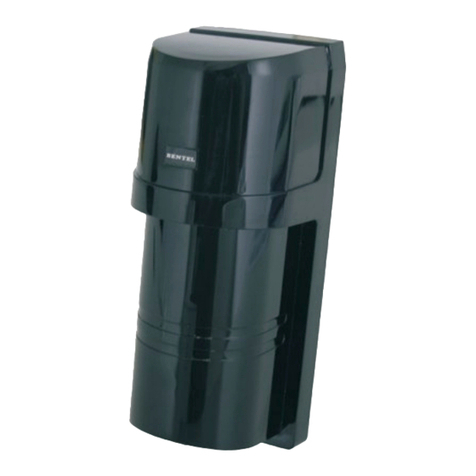
Bentel Security
Bentel Security RAY60-S User manual

Bentel Security
Bentel Security FC450IB User manual
Bentel Security
Bentel Security DT800 User manual

Bentel Security
Bentel Security BL151 User manual
Bentel Security
Bentel Security FC400H User manual
Bentel Security
Bentel Security BMD503 User manual

Bentel Security
Bentel Security ZT100H User manual

