TESTING
1) All the alarm signal services, releasing device and extinguisher system
should be disengaged during the test period and must be re-engaged
immediately at the conclusion of testing.
2) After energizing the detector head for approximately one minute, check
to see the indicator red LED flashing once every 4-6 seconds. If red LED
fails to flash, it indicates the non-functioning of the detector or faulty wir-
ing. Re-check the wiring or replace the detector if necessary.
CAUTIONS
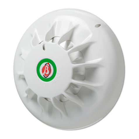
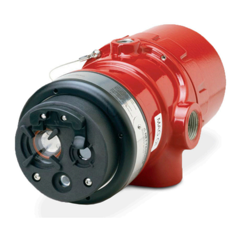
This heat detector is particularly designed to initiate and activate emer-
gency action, but will do so only when it is used in conjunction with an autho-
rized fire alarm system.
The purpose of design of heat detectors is meant to protect property,
not life. The heat detectors do not provide early warning of fire and cannot de-
tect smoke, gas, combustion particles, or flame. They will alarm when temper-
ature at the heat detector reach 57°C (135°F) or above. Given the rapid
growth of certain types of fires, heat detectors cannot be expected to provide
adequate warning of fires resulting from smoking in bed, inadequate fire pro-
tection practices, violent explosions, escaping gas, and improper storage of
flammable liquids like cleaning solvents, other safety hazards, or arson.
SPECIFICHE
http:www.bentelsecurity.com
Heat detectors do not always detect fires because the fire may be a
slow-smoldering, low-heat type (producing smoke), or because they may not
be mean where the fire occurs, or because the heat of the fire may bypass
them. Heat detectors will not detect smoke, gas, flames, or combustion particles.
Heat detectors are components in professionally installed fire alarm sys-
tems. They will not function if theyhave been improperly wired into the
fire alarm system or if power to them is disconnected for any reason.
Heat detectors cannot last forever. They should be tested and maintained
following the instructions in this manual. To be safe, they should be replaced
after they have been installed for ten years.
+CAUTION: DO NOT ATTEMPT TO DISASSEMBLY OF THE
FACTORY SEALED HEAT DETECTOR. THIS ASSEMBLY IS
SEALED FOR YOUR PROTECTION AND IS NOT INTENDED TO BE
OPENED FOR SERVICING BY USERS. TO OPEN THE DETECTOR
HEAD WILL VOID THE WARRANTY.
RECYCLING INFORMATION
BENTEL SECURITY recommends that customers dispose of their used
equipments (panels, detectors, sirens, and other devices) in an environ-
mentally sound manner. Potential methods include reuse of parts or whole
products and recycling of products, components, and/or materials.
For specific information see
www.bentelsecurity.com/en/environment.htm
WASTE ELECTRICAL AND ELECTRONIC EQUIPMENT (WEEE)
DIRECTIVE
In the European Union, this label indicates that this product
should NOT be disposed of with household waste. It should be
deposited at an appropriate facility to enable recovery and re-
cycling.
For specific information see
www.bentelsecurity.com/en/environment.htm
BENTEL SECURITY s.r.l. reserves the right to change the technical specifi-
cations of this product without prior notice.
HEAT SENSOR
RELAY
LED
POSITION
SETTING
FIG. 3 Schematic of Detector With Front Cover Open
Model 2/4 wire Voltage DC
Standby
Current
(Max.)
Alarm
Current
(Max.)
Surge
Current
(Max.)
Start-Up
Time
(Max.)
Permissible
Current
(Max.)
Frequency Alarm contact
ZT100H 2 10~35 V 55 µA50 mA 150 µA60 s 80 mA 4-6 s
ZT100HL 210~35 V 55 µA50 mA 150 µA60 s 80 mA 4-6 s
ZT100HR1 410~15 V 55 µA50 mA 150 µA60 s 80 mA 4-6 s Form A
ZT100HR2 421~27 V 55 µA50 mA 150 µA60 s 80 mA 4-6 s Form A

