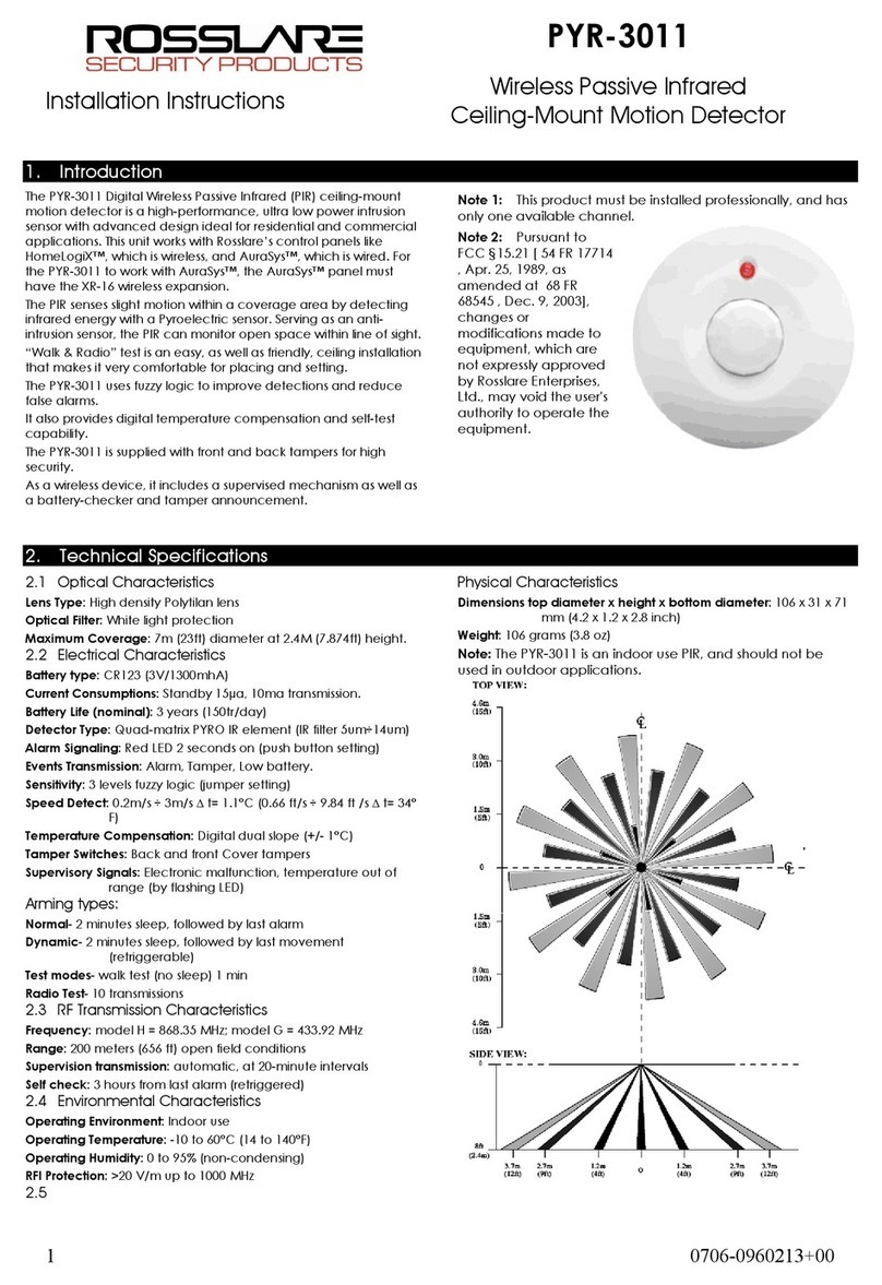
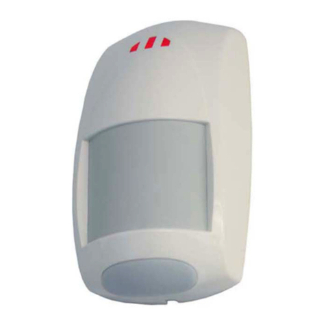
Bentel Security DT800 User manual

1
ITALIANO
Il DT800 è un rilevatore a doppia tec-
nologia (infrarosso + microonda) dispo-
nibile in quattro versioni, come mostra-
to nella tab 1; ogni versione è disponi-
bile in due frequenze di funzionamen-
to, così da poter installare due rilevato-
ri nello stesso ambiente, senza che
questi interferiscano tra loro Le istru-
zioni presenti in questo foglio sono va-
lide per tutte le versioni, salvo indica-
zioni diverse
COPERTURA
La copertura di questo rilevatore è
costituita dalle seguenti zone sensibili:
11 a lungo raggio + 13 a lungo/medio
raggio + 8 a medio raggio + 5 a corto
raggio
In Figura 1A e 1B è mostrata la copertu-
ra massima dei rilevatori DT800-B,
DT800-M e DT800-K, mentre in Figura
1D e 1E è mostrata la copertura massi-
ma del rilevatore DT800-PM: la linea trat-
teggiata rappresenta la copertura mas-
sima della microonda
Antistrisciamento
(solo DT800-B, DT800-M e DT800-K)
La copertura dei rilevatori DT800-B,
DT800-M e DT800-K si estende fino alla
parete sulla quale sono fissati (vedere
C in Fig 1), impedendo ad un eventua-
le intruso di eludere la sorveglianza
strisciando lungo la parete stessa
INSTALLAZIONE
Scegliere il punto per il fissaggio del
Rilevatore rispettando le seguenti in-
dicazioni:
¾fissare il Rilevatore ad un’altezza
compresa tra 1,95 e 3 m (si consiglia
2,3 m);
ENGLISH
The DT800 is a dual technology detec-
tor (infrared + microwave) available in
four versions, as shown in tab 1; each
version is available in two functioning
frequencies, so as to be able to install
two detectors in the same room, without
these interfering with each other
The instructions presented on this sheet
are valid for both versions, unless
otherwise indicated
COVERAGE
The coverage of this detector is provid-
ed by the following zones: 11 Long
Range + 13 Long/Intermediate Range
+ 8 Intermediate Range + 5 Short
Range In Figure 1A and 1B the cover-
age of the DT800-B, DT800-M and
DT800-K detectors is shown, while in
Figure 1D and 1E the coverage of the
DT800-PM detector is shown: the dot-
ted line represents the microwave cov-
erage
Look Down
(only DT800-B, DT800-M and DT800-
K)
The coverage of the DT800-B, DT800-
M and DT800-K detectors is extended
up until the wall on which they are mount-
ed (see C in Fig 1), so an eventual in-
truder sneaking against this wall will
also be detected
INSTALLATION
Choose the mounting location accor-
ding to the following indications:
¾mount the detector at a height
between 1 95 and 3 m (the
recommended height is 2 3 m )
FRANÇAIS
Le DT800 est un détecteur à double tech-
nologie (infrarouges+hyperfréquence)
disponible en quatre modèles, comme
indiqué dans le tableau 1; deux fréquenc-
es de fonctionnement sont disponibles
pour chaque modèle, de sorte qu’il est
possible d’installer deux détecteurs dans
le même local, sans qu’ils interfèrent en-
tre eux Les instructions présentes dans
cette notice sont valables pour toutes les
versions, sauf indications contraires
COUVERTURE
La portée de ce détecteur est assurée
par les zones de détection suivantes: 11
Longue + 13 Longue/Intermédiaire + 8
Intermédiaire + 5 Courte Les figures 1A
et 1B montrent la couverture des détect-
eurs DT800-B, DT800-M et DT800-K, al-
ors que les figures 1D et 1E montrent la
couverture du détecteur DT800-PM: la
ligne en pointiller représente la couver-
ture de l’hyperfréquence
Faisceaux de pied Anti rampement
(seulement DT800-B, DT800-M et DT800-
K)
La couverture des détecteurs DT800-B,
DT800-M et DT800-K s’étend jusqu’au
mur sur lequel ils sont montés (voir C de
Fig 1), en empêchant à tout intrus
éventuel d’éluder la surveillance en se fau-
filant le long du mur
INSTALLATION
Choisissez le point pour le montage du
Détecteur en respectant les indications
suivantes:
¾monter le Détecteur à une hauteur
comprise entre 1,95 et 3 m (hauteur
conseillée 2,3 m);
ISTISBL1DT800B-D 4.0 170908 P70
DT800
Rilevatore a doppia tecnologia
Dual technology detector
Détecteur double technologie
Detector de tecnología doble
MADE IN ITALY
ESPAÑOL
El DT800 es un detector de tecnología
doble (infrarrojos + microondas) disponible
en cuatro versiones, como se indica en la
tabla 1; cada versión se encuentra
disponible con dos frecuencias de
funcionamiento, de modo que se puedan
instalar dos detectores en el mismo
ambiente sin que interfieran entre sí Las
instrucciones presentes en esta hoja son
válidas para todas las versiones, salvo
indicación en contrario
ALCANCE
El alcance de este detector se compone
de las siguientes zonas sensibles: 11
de gran alcance + 13 de grande a
mediano alcance + 8 de medio alcance
+ 5 de corto alcance En la figura 1A y
1B se indica el alcance máximo de los
detectores DT800-B, DT800-M y
DT800-K, mientras que en la figura 1D
y 1E se indica el alcance máximo del
detector DT800-PM: la línea
segmentada representa el alcance
máximo de las microondas
Antideslizamiento
(sólo DT800-B, DT800-M y DT800-K)
El alcance de los detectores DT800-B,
DT800-M y DT800-K se extiende hasta
la pared sobre la cual se fijan (ver C en
la Fig 1), impidiendo a un intruso que
eluda la vigilancia deslizándose por la
pared
INSTALACIÓN
Elegir el punto para fijar el detector
respectando las siguientes indicaciones:
¾Fijar el detector a una altura de entre
1,95 y 3 m (se aconseja a 2,3 m);
!"#
!"#
$%!"&
!"#
'(((
)$%*
'+(
'
+
,-./()0
,-.)/0
,-.1 /0
,-. /0
zzz
zzz
zz z
zz

2
¾NON puntare il Rilevatore su
superfici riflettenti, come specchi
o finestre, poiché possono
distorcere l’area di copertura o
riflettere i raggi solari direttamente
sul Rilevatore;
¾NON fissare il Rilevatore in punti
sottoposti a forti correnti d’aria,
come vicino alle uscite dell’aria
condizionata;
¾NON fissare il Rilevatore vicino a
fonti di umidità, di vapore o
idrocarburi;
¾NON limitare la copertura del
Rilevatore con ostacoli di grandi
dimensioni come piante o armadietti
mmunità agli animali
domestici (solo DT800-
PM)
Affinché il rilevatore DT800-PM sia im-
mune agli animali domestici, il cui peso
complessivo NON superi i 20 Kg, oltre
alle indicazioni generali, rispettare le
seguenti indicazioni:
¾NON puntare il Rilevatore su un
vanoscala a cui ha accesso un
animale domestico;
¾NON fissare il Rilevatore a meno di
3 m da mobili o oggetti alti più di 0,9
m, sui quali può salire un animale
domestico;
¾NON angolare il Rilevatore verso il
basso
Fissaggio in piano, ad
angolo o a bandiera
1. Aprire il Rilevatore: svitare la vite 26,
se presente; infilare un piccolo
giravite piatto nell’apertura 21 e
premere delicatamente verso i LED
2. Rimuovere la Scheda Elettronica:
premere verso il basso il gancio 20
¾DO NOT position the detector
towards reflecting surfaces such as
mirrors or windows, as these can
distort the coverage area or reflect
the sun's rays directly onto the
detector;
¾DO NOT mount the detector in
places exposed to sources of air flow
such as close to air conditioning
vents;
¾DO NOT mount the detector near
sources of humidity, steam or
hydrocarbons;
¾DO NOT restrict the coverage of the
detector with large obstacles such
as plants or closets
Pet immunity
(only DT800-PM)
In order for the DT800-PM detector to
be immune to pets that DO NOT exceed
20 kg, together with the general instruc-
tions, follow these indications:
¾DO NOT position the detector
towards a stairwell to which pets
have access;
¾DO NOT mount the detector less then
3 m from furniture or objects higher
than 0 9 m, onto which pets can
climb;
¾DO NOT angle the detector
downwards
Wall mount, corner
mount or side mount
1. Open the detector: remove screw 26
if present; insert a small flat blade
screwdriver into opening 21 and
push delicately towards the LED
2. Remove the electronic board: push
hook 20 downwards
¾NE PAS orienter le Détecteur sur des
surfaces réfléchissantes comme les
miroirs ou les fenêtres, car elles
peuvent déformer la zone de
couverture ou réfléchir les rayons du
soleil directement sur le Détecteur;
¾NE PAS monter le Détecteur dans des
endroits soumis à de forts courants
d’air, comme près des sorties de l’air
conditionné;
¾NE PAS monter le Détecteur à proximité
de sources d’humidité, de vapeur ou
d’hydrocarbures;
¾NE PAS limiter la couverture du
Détecteur au moyen d’obstacles de
grandes dimensions comme plantes
ou petites armoires
mmunité aux animaux
domestiques (seulement
DT800-PM)
Pour que le détecteur DT800-PM pu-
isse être ”immunisé” à la présence des
animaux domestiques, dont le poids
total NE dépasse PAS 20 Kg, outre les
indications générales, il est nécessaire
de respecter les instructions suivantes:
¾ NE PAS orienter le Détecteur vers une
cage d’escalier accessible aux animaux
domestiques;
¾ NE PAS monter le Détecteur à moins de 3
m de meubles ou objets dont la hauteur se-
rait supérieure à 0,9 m sur lesquels pourrait
grimper un animal domestique;
¾ NE PAS diriger le Détecteur vers le bas
Montage par la plaque
arrière, en coin/
latéralement ou en
drapeau
1. Ouvrez le Détecteur: dévissez la vis 26,
si présente; enfilez un petit tournevis à
tête plate dans l’ouverture 21 et pressez
doucement vers les LEDs
2. Enlevez la Carte Électronique:
déplacez vers le bas le crochet 20
Fig. 1 - Copertura DT800-B, BT800-M e DT800-K: A) vista in pianta; B) vista laterale; C) antistrisciamento. Copertura DT800-PM: D) vista in pianta; ) vista laterale.
Fig. 1 - DT800-B, BT800-M and DT800-K coverage: A) top view; B) side view; C) sneak cover. DT800-PM coverage: D) top view; ) side view.
Fig. 1 - Couverture DT800-B, BT800-M et DT800-K: A) vue de dessus; B) vue latérale; C) Faisceaux de pied Anti rampement. Couverture DT800-PM: D) vue de dessus; ) vue latérale.
Alcance DT800-B, BT800-M y DT800-K: A) vista en planta; B) vista lateral; C) antideslizamiento. Alcance DT800-PM: D) vista en planta; ) vista lateral.
¾ NO apuntar el detector sobre
superficies que reflejen, como
espejos ó ventanas, debido a que
pueden distorsionar el área de
alcance ó reflejar los rayos solares
directamente sobre el detector
¾ NO fijar el detector en puntos
sometidos a fuertes corrientes de
aire, tales como salidas de aire
acondicionado
¾NO fijar el detector cerca de fuentes
de humedad, de vapor ó de
hidrocarburos
¾NO limitar el alcance del detector
con obstáculos de gran tamaño
como plantas ó armarios
nmunidad para los
animales domésticos
(sólo DT800-PM)
Para que el detector DT800-PM sea
inmune a los animales domésticos, cuyo
peso total NO debe superar los veinte
kgs, además de las indicaciones gene-
rales, se deben respetar las siguientes
indicaciones:
¾NO dirigir el detector a una zona de
escalera por donde tenga acceso
el animal
¾NO fijar el detector a menos de tres
metros de muebles u objetos altos
más de 0,9 m, sobre los que puede
subir un animal doméstico
¾NO apuntar el detector hacia abajo
Montaje en plano, en
ángulo ó de costado.
1. Abrir el detector: Aflojar el tornillo 26,
si está presente, introducir un
pequeño destornillador plano en la
abertura 21 y presionar de forma
delicada hacia los LED
2. Quitar la tarjeta electrónica:
presionar hacia abajo el gancho 20

3
3. Aprire il foro 17a o 17b o 17c per il
fissaggio i piano; aprire i fori 16a e
16c oppure i fori 16b e 16d per il
fissaggio ad angolo; aprire i fori 16a
e 16b oppure i fori 16c e 16d per il
fissaggio a bandiera
. Aprire il foro 19a o 19b o 19c per il
passaggio del cavo per i
collegamenti
5. Passare il cavo per i collegamenti
attraverso il foro predisposto,
quindi fissare il Fondo al muro
tramite le viti in dotazione
6. Riagganciare la Scheda Elettronica
al Fondo: inserire il lato superiore
della Scheda sotto i ganci 18, quindi
premere sul lato inferiore della
Scheda verso il Fondo
7. Eseguire i collegamenti sulla
morsettiera
8. Impostare il modo di funzionamenro
del Rilevatore, come descritto nei
relativi paragrafi
9. Chiudere il Rilevatore: agganciare
il lato superiore del Coperchio al
Fondo quindi spingere sul lato
inferiore del Coperchio fino a udire
uno scatto; se previsto, bloccare il
Coperchio tramite la vite 26 (non
fornita)
10. Eseguire la Prova di Copertura,
come descritto nel relativo
paragrafo
Fissaggio su
canalizzazioni a vista
Tramite la Base 23 fornita di serie, è
possibile fissare il Rilevatore su cana-
line da 15 mm, come descritto di segui-
to
1. Procedere come per l’installazione
in piano, ad angolo o a bandiera,
fino al punto 5
2. Aprire i settori 22a o 22b
3. Open hole 17a or 17b or 17c for the
wall mount; open holes 16a and
16c or holes 16b and 16d for the
corner mount, open holes 16a and
16b or holes 16c and 16d for the
side mount
. Open hole 19a or 19b for the
passage of the connecting cable
5. Pass the connecting cable through
the appropriate hole, then attach the
back plate to the wall with the
screws supplied
6. Reattach the electronic board to the
back plate; insert the top part of the
board underneath hooks 18, then
press on the lower part of the board
towards the back plate
7. Carry out the connections on
terminal board
8. Set the operating mode of the
detector as described in the relative
paragraphs
9. Close the detector: hook the top
part of the cover to the backplate
then push onto the bottom part of
the cover until you hear a click; the
cover can be secured with screw 26
(not supplied)
10. Carry out the walk test as described
in the relative paragraph
Surface wiring mount
With the base 23, series provided, it is
possible to mount the detector on 15
mm wire channels, as described in the
following
1. Proceed as for the wall, corner or
side mount, until n 5
2. Open areas 22a or 22b
3. Ouvrez la pré perçage 17a ou 17b
ou 17c pour le montage par la plaque
arrière ; ouvrez les pré perçages 16a
et 16c ou les pré perçages 16b et
16d pour le montage en coin; ouvrez
les pré perçages 16a et 16b ou les
pré perçages 16c et 16d pour le
montage en drapeau
. Ouvrez le passage de câble 19a ou
19b ou 19c pour permettre le passage
du câble pour les connexions
5. Insérez le câble pour les connexions
dans le passage de câble, ensuite
fixez la plaque arrière au mur au
moyen des vis en dotation
6. Repositionnez la Carte Électronique
sur la plaque arrière: insérez le côté
supérieur de la Carte sous les crochets
18, puis pressez sur le côté inférieur
de la Carte vers la plaque arrière
7. Effectuez les connexions sur la plaque
à bornes
8. Programmez le mode de
fonctionnement du Détecteur, ainsi
que décrit dans les paragraphes
correspondants
9. Fermez le Détecteur: accrochez le côté
supérieur du Couvercle à la plaque
arrière puis poussez sur le côté
inférieur du Couvercle jusqu’à ce que
vous entendrez un enclenchement; si
prévu, bloquez le Couvercle au moyen
de la vis 26 (non fournie)
10. Effectuez un test de fonctionnement,
ainsi que décrit dans le paragraphe
relatif
Montage sur goulottes
saillies
À l’aide de la Base 23 fournie de série,
il est possible de monter le Détecteur
sur des goulottes de 15 mm, comme
décrit plus bas.
1. Procédez comme pour l’installation
par la plaque arrière, en coin/
latéralement ou en drapeau,
jusqu’au point 5
2. Ouvrez les secteurs 22a ou 22b
!
"#
#
#
$
$$
%
&'()
!"#$%&'(
*+)
!"#$(
*+)
)#!
!" # $%&'(
#*+
! !" # $ (
#*+
,-
!"$%&
'(*
*+*
!"$(
**+
+
$.!
, !" - $ %
&'(
.*+.
! !"-$%//(
*+
.
(&'
0123$2
/)#
0123$2
,"#,#
0123$2
$
0123$2
0
0
!
4
!
(++
(+
+
%(++
(+
+
!#!1
(++
*
*(++
*
!
(++
(+
+
3. Abrir el orificio 17a ó 17b ó 17c para
el montaje en plano; abrir los orificios
16a y 16c ó bien los orificios 16b y
16d para el montaje en ángulo; abrir
los orificios 16a y 16b ó bien los
orificios 16c y 16d para el montaje
de costado
. Abrir el orificio 19a ó 19b ó 19c para
hacer pasar el cable de las
conexiones
5. Pasar el cable de las conexiones a
través del orificio ya preparado,
luego fijar el fondo a la pared con
los tornillos en dotación
6. Enganchar la tarjeta electrónica al
fondo: Introducir el lado superior de
la tarjeta debajo de los ganchos 18,
luego presionar el lado presionar
sobre el lado inferior de la tarjeta
hacia el fondo
7. Realizar las conexiones en la
bornera
8. Programar el modo de
funcionamiento del detector como
se describe en los párrafos relativos
9. Cerrar el detector: enganchar el
lado superior de la tapa al fondo,
luego empujar en el lado inferior de
la tapa hasta oír un sonido; si se
prevé, bloquear la tapa con el tornillo
26 (no en dotación)
10. Realizar la prueba de alcance, como
se describe en el relativo párrafo
Montaje en canaletas a la
vista.
Por medio de la base 23 suministrada
de serie se puede fijar el detector en
canaletas de 15 mm, como se describe
a continuación
1. Proceder como para la instalación
en plano, en ángulo ó de costado,
hasta el punto 5
2. Abrir los sectores 22a ó 22b

4
3. Passare il cavo per i collegamenti
attraverso il foro 19a o 19b o 19c
della Base, quindi appoggiare la
Base al muro, sopra la canalina
. Passare il cavo per i collegamenti
attraverso il foro 19a o 19b o 19c
del Fondo, quindi fissare il Fondo
più la Base al muro, tramite le viti in
dotazione
3. Pass the connecting cable through
opening 19a or 19b or 19c of the
base, then position the base to the
wall, above the channel
. Pass the connecting cable through
opening 19a or 19b or 19c of the
back plate, then attach the back
plate and the base to the wall, with
the supplied screws
3. Insérez le câble dans le passage
de câble 19a ou 19b ou 19c de la
Base, puis appuyer la Base au mur,
sur la goulotte
. Insérer le câble dans le passage
de câble 19a ou 19b ou 19c de la
plaque arrière, puis fixer la plaque
arrière plus la Base au mur, à l’aide
des vis en dotation
2.3.&. &..+2. 2.3.&. 2.3.&.4
2.&4))4
&.2. 2.&45.
2.&464
2.*224 7.22482.# 2.65+. 2.&*224
5 67 67
!"#8 " !"9# ! !" ! !"
"28:; 24:; 52:; "2:;
"#88
#84# 5#8
"#8
, ! 5 ,4
,<
!#
,
*
,4
# =# !9 4
,<
#
#
,
*
,
, # 5 ,
& =>??9 =>??9"' & =>??9 =>??9
"'
& =>??9
=>??9"' & =>??9 =>??9"'
,<& =>??9
=>??9"'
& =>??9
=>??9"'#
,&
=>??9 =>??9"'
*
,& =>??9
=>??9"'
/@ ") /
/ 59 "A %4.
/9:
)/
B99:
"A
)A9:
)
%4
9:.
C,
; D 55
E
C 4 4
/9;0
)/
D9;0
"A
FA0G
)
%
9;0.
C,
; D 55
E
C44
C5 D 55 C4
, H# ,< ,
6888
6# 6
648
5 5 5 =
,; ; 5E =4;
25
&%'
,#&
'
25&%
' =4&%'
",
, 5# "F,
@
"
,, ,# ,@ ,
25
/,
,#
#
25
)
=4
"5
, 5# "F5
"
H*" % %*" H
5, ,# 5 =
", ,# " "
/, ,# ") /
#,&
'
,##&
'
!9&%
'
4
&'
/=
H D89# "A7
5H %4
/, D# "A7
%4
"/
, 5#"F)
"
3. Pasar el cable para las conexiones
por medio del orificio 19a ó 19b ó
19c de la base, luego apoyar la base
a la pared, arriba de la canaleta
. Pasar el cable de las conexiones
por medio del orificio 19a ó 19b ó
19c del fondo, después fijar el
fondo más la base a la pared
utilizando los tornillos en dotación

5
0B<=2
=08=6
2
E
G
E E
D
F
D
F
F
D
E
$ % &
'
(
E
)
FD D FD
E
E
D
G
E
D F E
D
*
Fig. 2 - Identificazione delle parti - Parts Identification - Identification des composants - Identificación de las partes.
.

6
5. Procedere come per l’installazione
in piano, ad angolo o a bandiera,
dal punto 8
Fissaggio tramite lo
Snodo
Tramite lo snodo opzionale BR-01 è
possibile fissare il Rilevatore a parete o
a soffitto, ruotarlo in senso orizzontale
di ±45° e inclinarlo fino a 5° verso il bas-
so
Lo snodo BR-01 non è certificato
IMQ.
1. Procedere come per l’installazione
in piano, ad angolo o a bandiera,
fino al punto 2
2. Aprire i fori 17a e 19b sul Fondo del
Rilevatore
3. Per il fissaggio a parete, aprire il foro
37a o 37b, il foro 38b ed il foro 36a,
se è previsto il Deviatore
Antisabotaggio
Per il fissaggio a soffitto, aprire il foro
37c o 37d, il foro 38a ed il foro 36b,
se è previsto il Deviatore
Antisabotaggio
. Passare il cavo per i collegamenti
attraverso il foro 38, quindi fissare
il Fondo tramite il foro 37 e, se è
previsto il Deviatore
Antisabotaggio, fissare il Tassello
Antisabotaggio tramite il foro 36
5. Se previsto, posizionare il Deviatore
Antisabotaggio (non fornito) nel
Coperchio, come mostrato in Figura
2F
La levetta del Deviatore deve es-
sere orientata come mostrato in
Figura 2F altrimenti il dispositivo
non funziona correttamente.
6. Se previsto, collegare il Deviatore
Antisabotaggio in serie alla linea
antisabotaggio
7. Infilare il Perno 33 nell’apertura 31,
passare il cavo per collegamenti
attraverso l’apertura 30, quindi
fissare il Coperchio al Fondo tramite
la vite 29
8. Accoppiare il Supporto 28 al Fondo
del Rilevatore, quindi passare il cavo
per i collegamenti, prima attraverso
l’apertura 27, poi attraverso il foro
19b
9. Fissare il Fondo più il Supporto al
perno 33, tramite la vite in dotazione,
senza serrare
10. Orientare il Fondo nella direzione
desiderata, quindi serrare la vite
11. Procedere come per l’installazione
in piano, ad angolo o a bandiera,
dal punto 8
5. Proceed as for the wall, corner or
side mount, from n 8
Swivel Mount
With the BR-01 optional swivel, it is
possible to wall mount or ceiling mount
the detector, rotate it ±45° horizontally,
and tilt it up to 5° downwards
The BR-01 swivel is not IMQ.
1. Proceed as for the wall, corner or
side mount until n 2
2. Open holes 17a and 19b on the
back plate of the detector
3. For the wall mount, open hole 37a
or 37b, holes 38b and 36a, if the
tamper switch is being fitted For the
ceiling mount, open hole 37c or
37d, holes 38a and 36b, if the
tamper switch is being fitted
. Pass the connecting cable through
hole 38, then attach the back plate
through hole 37 and, if the tamper
switch is being fitted, attach the
tamper bracket through hole 36
5. If it is being fitted, position the
tamper switch (not supplied), into
the cover, as shown in Fig 2F
The switch lever must be directed
as described in Fig. 2F otherwise
the device will not function correctly.
6. If it is being fitted, connect the
tamper switch in series to the tamper
line
7. Insert pivot 33 into opening 31,
pass the connecting cable
through opening 30, then attach
the cover to the back plate with
screw 29
8. Couple support 28 to the back plate
of the detector, then pass the
connecting cable first through
opening 27, then through hole 19b
9. Attach the back plate and the
support to pivot 33 with the screws
given, without tightening
10. Direct the back plate forwards the
desired direction, then tighten the
screw
11. Proceed as for the wall, corner or
side mount, from n 8
5. Procédez comme pour l’installation
par la plaque arrière, en coin/
latéralement ou en drapeau, à partir
du point 8
Montage au moyen de
l’Articulation
Au moyen de l’articulation en option BR-
01 il est possible de monter le Détect-
eur au mur ou au plafond, de le tourner
en sens horizontal de ±45° et de l’incliner
jusqu’à 5° vers le bas
La rot le BR-01 n'est pas IMQ.
1. Procédez comme pour l’installation
par la plaque arrière, en coin/
latéralement ou en drapeau,
jusqu’au point 2
2. Ouvrez les pré perçages 17a et 19b
sur la plaque arrière du Détecteur
3. Pour le montage mural, ouvrez le
pré perçage 37a ou 37b, le pré
perçage 38b et le pré perçage 36a,
si le Commutateur Anti-sabotage est
prévu Pour le montage au plafond,
ouvrez le pré perçage 37c ou 37d,
le pré perçage 38a et le pré perçage
36b, si le Commutateur Anti-
sabotage est prévu
. Insérez le câble pour les connexions
dans l’entrée 38, puis fixez la plaque
arrière à travers la débouchure 37 et,
si le Commutateur Anti-sabotage est
prévu, fixez la Cheville Anti-sabotage
à travers le pré perçage 36.
5. Si prévu, positionnez le
Commutateur Anti-sabotage (non
fourni) dans le Couvercle, comme
indiqué dans la figure 2F
Le levier du Commutateur doit être
orienté comme indiqué dans la fi-
gure 2F autrement le dispositif ne
fonctionne pas correctement.
6. S’il est prévu, connectez le
commutateur Anti-sabotage en série
sur la ligne anti-sabotage
7. Enfilez le Pivot 33 dans l’ouverture
31, insérez le câble pour les
connexions dans l’ouverture 30, puis
fixer le Couvercle à la plaque arrière
à l’aide de la vis 29
8. Emmanchez le Support 28 à la
plaque arrière du Détecteur, puis
insérez le câble pour les connexions,
d’abord à travers l’ouverture 27,
ensuite à travers la débouchure
19b
9. Fixez la plaque arrière plus le Support
au pivot 33, à l’aide de la vis en
dotation, sans serrer
10. Orientez la plaque arrière dans la
direction souhaitée, puis serrez la
vis
11. Procédez comme pour l’installation
par la plaque arrière, en coin/
latéralement ou en drapeau, à partir
du point 8
!
! "#$%
"#$%&
!
&' (#
)# *+ #
"#$%
"#$%&
!
'&' *
#',#-
"#$%
5. Proceder del mismo modo que para
la instalación en plano, en ángulo ó
de costado, a partir del punto 8
Montaje con la
Articulación
Con la articulación opcional BR-01 es
posible fijar el detector a la pared ó al
cielorraso, girarlo en sentido horizontal
± 45° e inclinarlo hasta 5° hacia abajo
La artic lación BR-01 no está
certificada IMQ.
1. Proceder como para la instalación
en plano, en ángulo ó de costado,
hasta el punto 2
2. Abrir los orificios 17a y 19b en el fondo
del detector
3. Para el montaje a la pared, abrir el
orificio 37a ó 37b, el orificio 38b y el
orificio 36a si está previsto el
desviador antisabotaje Para el
montaje al cielorraso, abrir el orificio
37c ó 37d, el orificio 38a y el orificio
36b, si está previsto el desviador
antisabotaje
. Pasar el cable de las conexiones
por medio del orificio 38, luego fijar
el fondo mediante el orificio 37 y, si
está previsto el desviador
antisabotaje, fijar el taco
antisabotaje utilizando orificio 36
5. En caso de estar previsto, colocar el
desviador antisabotaje (no de serie)
en la tapa como lo muestra la figura
2F
La palanca del desviador debe
orientarse tal como se indica en la
figura 2F; de lo contrario, el
dispositivo no funcionará de forma
correcta.
6. Si está previsto, conectar el
desviador antisabotaje en serie con
la línea antisabotaje
7. Introducir el perno 33 en la abertura
31, pasar el cable para conexiones
a través de la abertura 30, y luego
fijar la tapa al fondo utilizando el
tornillo 29
8. Acoplar el soporte 28 al fondo del
detector, luego pasar el cable de
las conexiones, primero por la
abertura 27, luego a través del
orificio 19b
9. Fijar el fondo más el soporte al perno
33, utilizando el tornillo en dotación
y sin ajustar
10. Orientar el fondo en la dirección
deseada, luego ajustar el tornillo
11. Proceder del mismo modo que para
la instalación en plano, en ángulo ó
de costado, a partir del punto 8
% %
!
. /
0)#
* # "#$# %

7
COLLEGAMENTI
Usare cavo schermato per il collegamen-
to del Rilevatore: collegare lo schermo
alla massa della centrale, lasciandolo
scollegato dalla parte del Rilevatore Se
la distanza tra il Rilevatore e la centrale
è notevole, assicurarsi che non vi sia
caduta di tensione (la tensione di ali-
mentazione deve essere compresa tra
9 e 15 V)
Il Rilevatore impiega circa 60 se-
condi per stabilizzarsi, dal momen-
to in cui viene alimentato. Questo
periodo è segnalato dal L D rosso
acceso.
Antimascheramento (solo
DT800-K)
Il DT800-K è in grado di segnalare, tra-
mite i morsetti M e G, se uno dei suoi
sensori viene mascherato:
CONNECTIONS
Use shielded cable for the connection
of the detector: connect the shield to
the control panel negative terminal,
and leave the other end (detector
end) disconnected If there is consid-
erable distance between the detector
and the control panel, check for
voltage drop (required voltage range:
9 V to 15 V)
The detector will stabilize approx-
imately 60 seconds after power
up. The stabilization phase will be
indicated by glowing on the red
L D.
Anti-masking (only DT800-
K)
The DT800 can signal when one of its
sensors is masked through terminal M
and G:
CONNEXIONS
Utiliser le câble blindé pour la connex-
ion du Détecteur: connectez l’écran à
la masse du tableau de commande, en
le laissant déconnecté du côté du Dé-
tecteur. Si le Détecteur est à une dis-
tance considérable du tableau de com-
mande, vérifiez qu’il n’y ait pas de
baisse de tension (tension requise: 9
V à 25 V).
Le Détecteur se stabilise au bout
d’environ 60 secondes, après la
mise en marche. La phase de sta-
bilisation sera indiquée par un
voyant L D rouge.
Anti-masque (seulement
DT800-K)
Le DT800-K est en mesure de signaler, à
travers les terminaux M et G, le masquage
de l’un de ses capteurs :
!"#$
$$""$%$
&'
$$"$("
!
"#$ %& !
"#$ ' (
"#)
!
#$
* !
+#$ %&* !
+#$ ' *(
+#)
!#$
,--.&
//
0
1.
,-.'&
2
/ 0 1
3,!
-
3,!
(3-,!-.
-
3 ,!
.'
'0,!/
0-
0'0,!2
43,!1
.
&3,!
1
3 ,!
3,!
(3,!
.'
3 - ,!
-.
'0,!2
0'0
,!/
43,!1
&3,!
1.
! ! "#$"
/
3,!
-
3 ,!
#
(3-,!-.
-
3 ,!
.' #
'0,!/
0-
0'0,!2
#
43,!1
.
&3,!
1
3 ,!
3 ,!
(3,!
.'
3 - ,!
-.
'0,!2
0'0
,!/
43,!1
&3,!
1.
%& ! #' ! #' #$" #&% ( !
X:
5
5
5
5
3,!
-
3,!
#
(3-,!-.
-
3 ,!
.' #
'0,!/
0-
0'0,!2
#
43,!1
.
&3,!
1
3 ,!
3,!
(3,!
.'
3 - ,!
-.
'0,!2
0'0
,!/
43,!1
&3,!
1.
%& ! #' ! #' #$" #&% ( !
CONEXIONES
Utilizar cable blindado para la conexión
del Detector: conectar la pantalla a
masa de la central, dejándolo
desconectado de la parte del detector
Si la distancia entre el detector y la central
es importante, asegurarse que no haya
caída de tensión (la tensión de
alimentación debe estar comprendida
entre 9 y 15 V)
l detector emplea aproximadamente
60 segundos para estabilizarse a
partir del momento en que es
alimentado. ste período es
indicado por el L D rojo encendido.
Antienmascaramiento
(sólo DT800- K)
El DT800-K es capaz de indicar, por
medio de los bornes M y G, si uno de sus
sensores está enmascarado:

8
!"
# # #$ #%
&''
'()*++,"
' ()*++,"
--
'()*++,"
''
%'()*++,"
.' ' .'' .'%
./ ./%
!
0'' .' 1' 2'' " #
''' .'' '1' ''
0/ ) ,/ 2'/ " #
2/'&
'()*++, ()*++,"
' ()*++,()*++,"
2/'
'()*++,()*++,
"
2/''%
%'()*++,()*++,"
$
!
) ) ) %#
' ' %
( 3-$-" ( 3-$-" ( 3-$-" ( 3-.-" &' (
4 (
¾en veille, les terminaux M et G sont
connectés;
¾en cas de masquage de l’un des deux
capteurs, les terminaux M et G se
déconnectent
Pour un fonctionnement correct de
l’anti-masque, la sensibilité des
capteurs infrarouges et
hyperfréquence du détecteur
DT800-K doit être similaire.
Microphone
(seulement DT800-M et
DT800-PM)
Les détecteurs DT800-M et DT800-PM
sont dotés d’un microphone qui, étant
connecté centrales ou transmetteurs
prédisposés, permet d’écouter via télé-
phone les sons présents dans le local où
ils sont installés
¾Les terminaux M et G du Détecteur
sont, respectivement, le microphone
et la masse
¾À travers le potentiomètre1 il est
possible de régler la sensibilité du
microphone: en tournant le
potentiomètre dans le sens des aiguilles
d’une montre la sensibilité augmente
MODE DE
FONCTIONNEMENT “ET”
Le Détecteur déclenche l’alarme lorsque
ses capteurs génèrent, simultanément, le
nombre programmé d’impulsions, en
maximum 30 s (colonne ET de Tab 4)
Pour programmer le Mode ET des détec-
teurs DT800-B, DT800-M et DT800-K,
commutez l’interrupteur DIP n 1 sur ON
(par défaut)
¾on standby, terminals M and G are
connected;
¾if one of the two sensors is masked,
terminals M and G disconnect
For a proper functioning of the
anti-masking, the sensitivity of the
infrared and microwave sensors of
the DT800-K detector must be the
same.
Microphone
(only DT800-M and DT800-
PM)
The DT800-M and the DT800-PM de-
tectors are supplied with a microphone
that, connected to a suitable control
panel, allows for the listening of sounds
produced in the area in which they are
installed through the use of a phone
¾Terminals M and G of the detector
are respectively the microphone and
the negative terminal
¾It is possible to adjust the sensitivity
of the microphone through the
trimmer 1 : sensitivity increases by
turning the trimmer clockwise
AND MODE
The detector will go into alarm when its
sensors generate, at the same time,
the programmed number of pulses
within 30 s (AND column - Table 4) To
set the AND Mode of the DT800-B,
DT800-M and DT800-K detectors, turn
DIP switch no 1 ON (default)
¾a riposo, i morsetti M e G sono
collegati;
¾se uno dei due sensori viene
mascherato, il morsetti M e G si
scollegano
Per un corretto funzionamento del-
l’antimascheramento, la sensibilità
dei sensori infrarosso e microonda
del rilevatore DT800-K deve esse-
re simile.
Microfono
(solo DT800-M e DT800-
PM)
I rilevatori DT800-M e DT800-PM sono
dotati di un microfono che, collegato con
centrali predisposte, permette di ascol-
tare via telefono, i suoni prodotti nel-
l’ambiente nel quale sono installati
¾I morsetti M e G del Rilevatore sono,
rispettivamente, il microfono e la
massa
¾Tramite il trimmer 1 è possibile
regolare la sensibilità del microfono:
ruotando il trimmer in senso orario la
sensibilità aumenta
MODO AND
Il Rilevatore va in allarme quando i suoi
sensori generano, contemporaneamen-
te, il numero di impulsi programmati, in
un tempo massimo di 30 s (colonna AND
della Tab 4)
Per impostare il Modo AND dei rilevatori
DT800-B, DT800-M e DT800-K, commu-
tatare il DIP switch n 1 su ON (default)
¾En reposo, los bornes M y G están
conectados
¾Si uno de los dos sensores es
enmascarado, los bornes M y G se
desconectan
Para obtener un funcionamiento
correcto del antienmascaramiento,
la sensibilidad de los sensores
infrarrojos y microonda del detector
DT800-K debe ser similar.
Micrófono
(sólo DT800-M y DT800-
PM)
Los detectores DT800-M y DT800-PM
están dotados con un micrófono que al
conectarse con centrales
predispuestas, permite escuchar por
teléfono los sonidos producidos en el
ambiente donde se instalan
¾Los bornes M y G del Detector son
el micrófono y la masa
respectivamente
¾Mediante el trimmer 1 se puede
regular la sensibilidad del micrófono:
girando el trimmer en sentido
horario, aumenta la sensibilidad
MODO AND
El detector entra en estado de alarma
cuando sus sensores generan,
simultáneamente, el número de impulsos
programados, en un tiempo máximo de
30 s (columna AND de la Tabla 4)
Para programar el Modo AND de los
detectores DT800-B, DT800-M y
DT800-K, conmutar el Interruptor DIP
n° 1 en ON (por defecto)

9
Il Rilevatore DT800-PM può funzio-
nare solo in Modo AND.
MODO AND/OR
(solo DT800-B, DT800-M e DT800-K)
Oltre a funzionare come in Modo AND,
se uno dei due sensori viene maschera-
to, il Rilevatore va in allarme quando il
sensore funzionante genera il numero
di impulsi programmato, in un tempo mas-
simo di 30 s (colonna OR della Tab 4)
Per impostare il Modo AND/OR commu-
tare il DIP switch n 1 su OFF
ABILITAZIONE
MEMORIA
Questa funzione è utile quando si de-
vono collegare più rilevatori alla stessa
linea di una centrale, per sapere in quale
punto preciso è avvenuta l’intrusione:
se, a centrale disinserita, il LED rosso di
un rilevatore resta acceso, vuol dire che
quel rilevatore è andato in allarme La
memoria viene cancellata e il LED rosso
si spegne quando la centrale viene in-
serita Per abilitare la memoria:
¾commutare il DIP switch n 4 su ON;
¾collegare il morsetto IN del
Rilevatore ad una uscita che
segnala lo stato della centrale;
¾commutare il DIP switch n 3 su ON
se l’uscita è appesa quando la
centrale è disinserita, oppure
commutare il DIP switch n 3 su OFF
se l’uscita è a massa quando la
centrale è disinserita
Se il DIP switch n. 4 viene commu-
tato su OFF, la memoria è sempre
disabilitata, indipendentemente
dallo stato del morsetto IN.
DISABILITAZIONE LED
I LED di segnalazione possono essere
disabilitati a centrale disinserita, per non
recare disturbo, come descritto di se-
guito:
¾lasciare il ponticello L intatto;
¾collegare il morsetto IN del
Rilevatore ad una uscita che
segnala lo stato della centrale;
¾commutare il DIP switch n 3 su ON
se l’uscita è appesa quando la
centrale è disinserita, oppure
commutare il DIP switch n 3 su OFF
se l’uscita è a massa quando la
centrale è disinserita
Se il ponticello L viene tagliato, i
L D sono abilitati, indipendente-
mente dallo stato del morsetto IN.
The DT800-PM detector can only
operate on AND mode.
AND/OR MODE
(only DT800-B, DT800-M and DT800-
K)
Apart from operating as in AND Mode,
if one of the two sensors is masked, the
detector will go into alarm when the
working sensor generates a number of
programmed pulses, within 30 s (OR col-
umn - Tab 4)
To set the AND/OR Mode turn DIP switch
no 1 OFF
ENABLING MEMORY
This feature is used when several de-
tectors are connected to the same con-
trol panel zone If the detector signals
an alarm to the control panel, the red
LED will glow when the system disarms,
thus indicating the exact place of
violation The memory will clear and the
red LED will go OFF when the control
panel rearms To enable the memory:
¾turn DIP switch no 4 ON;
¾connect the IN terminal of the
detector to an output that signals
the control panel status;
¾turn DIP switch no 3 ON if the
output is floating when the control
panel is disarmed, or turn DIP switch
no 3 OFF if the output is negative
when the control panel is disarmed
If DIP switch no. 4 is turned OFF,
the memory is always disabled
independently from the state of the
IN terminal.
DISABLING THE LEDs
The LEDs can be disabled, with the
panel disarmed, so as not to cause
disturbances, by following these instruc-
tions:
¾leave jumper L intact;
¾connect terminal IN of the detector
to an output that signals the status
of the control panel;
¾turn DIP switch no 3 ON if the output
is floating when the panel is
disarmed, or turn DIP switch no 3
OFF if the output is negative when
the control panel is disarmed
If Jumper L is cut, the L Ds are
enabled, independently from the
state of jumper IN.
Le Détecteur DT800-PM ne peut
fonctionner qu’en Mode T.
MODE DE
FONCTIONNEMENT
“ET/OU“
(seulement DT800-B, DT800-M et
DT800-K)
Outre à fonctionner de la même façon
qu’en Mode ET, si l’un des deux capteurs
est masqué, le Détecteur déclenche
l’alarme lorsque le capteur qui fonctionne
génère le nombre programmé
d’impulsions, en maximum 30 s (voir col-
onne OU de Tab 4) Pour programmer le
Mode ET/OU commutez l’interrupteur DIP
n 1 sur OFF
ACTIVER LA
MÉMOIRE
Cette fonction est utile pour les
applications où plusieurs détecteurs sont
connectés en série à la même zone
d’une centrale d’alarme, pour connaî-
tre l’emplacement exact de la violation:
si, quand la centrale d’alarme est
désarmé la LED rouge d’un détecteur
reste allumée, cela veut dire que ce dé-
tecteur a déclenché l’alarme La
mémoire s’efface et la LED rouge s’éteint
lorsque la centrale d’alarme est réarmée
Pour activer la mémoire:
¾commutez l’interrupteur DIP n 4 sur
ON;
¾connectez le terminal IN du
Détecteur à une sortie qui signale
l’état de la centrale d’alarme;
¾commutez l’interrupteur DIP n 3 sur
ON si la sortie est en l’air quand la
centrale d’alarme est désarmée, ou
commutez l’interrupteur DIP n 3 sur
OFF si la sortie se ferme sur le pôle
négatif quand la centrale d’alarme
est désarmée
Si l’interrupteur DIP n. 4 est sur
OFF, la mémoire est toujours dé-
sactivée, indépendamment de
l’état du terminal IN.
DÉSACTIVER LES LED
Les L D de signalisation peuvent être
désactivés quand la centrale d’alarme
est désarmée de la manière suivante:
¾laissez le cavalier L intact ;
¾connectez le terminal IN du Détecteur
à une sortie qui signale l’état de la
centrale d’alarme ;
¾commutez l’interrupteur DIP n 3 sur
ON si la sortie est en l’air quand la
centrale d’alarme est désarmée, ou
commutez l’interrupteur DIP n 3 sur
OFF si la sortie se ferme sur le pôle
négatif quand la centrale d’alarme
est désarmée
Si le cavalier L est coupé, les L Ds sont
activées, indépendamment de l’état
du terminal IN
l Detector DT800-PM sólo puede
funcionar en Modo AND.
MODO AND/OR
(Sólo DT800-B, DT800-M y DT800-K)
Además de funcionar en Modo AND, si
uno de los dos sensores es enmascarado,
el Detector entra en estado de alarma
cuando el sensor de funcionamiento
genera el número de impulsos
programado, en un tiempo máximo de 30
s (columna OR de la Tabla 4)
Para programar el Modo AND/OR
conmutar el Interruptor DIP n° 1 a OFF
HABILITACIÓN DE LA
MEMORIA
Esta función es útil cuando deben
conectarse varios detectores en la
misma línea de una central, para saber
en que punto preciso se ha producido
la intrusión: Si al desconectarse la
central, el LED rojo de un detector
permanece encendido, significa que
ese detector ha entrado en alarma La
memoria es borrada y el LED rojo se
apaga cuando la central se conecta
Para habilitar la memoria:
¾Conmutar el interruptor DIP n° 4 a
ON
¾Conectar el borne IN del detector a
una salida que indica el estado de
la central
¾Conmutar el interruptor DIP n° 3 a
ON si la salida está colgada cuando
la central está desconectada ó bien
conmutar el Interruptor DIP n° 3 a
OFF si la salida en masa cuando la
central está desconectada
Si el Interruptor DIP n° 4 es
conmutado a OFF, la memoria está
siempre deshabilitada,
independientemente del estado del
borne IN.
DESHABILITACIÓN
LED
Los LED de señalización pueden
deshabilitarse con la central
desconectada, para no crear
interferencias, como se describe a
continuación:
¾Dejar el puente L intacto
¾Conectar el borne IN del detector a
una salida que indique el estado
de la central
¾Conmutar el Interruptor DIP n° 3 a
ON si la salida está colgada cuando
la central está desconectada o bien
conmutar el Interruptor DIP n° 3 a
OFF si la salida está en masa
cuando la central está
desconectada
Si el puente L es cortado, los L D
son habilitados de forma
independiente del estado del
borne IN.

10
DÉSACTIVER
L’HYPERFRÉQUENCE
(se lement DT800-B, DT800-M et
DT800-PM)
L’hyperfréquence peut être désactivée
quand la centrale d’alarme est désarmée,
afin de réduire la pollution électromag-
nétique, de la manière suivante:
¾laissez le cavalier uW intact ;
¾connectez le terminal IN du
Détecteur à une sortie qui signale
l’état de la centrale d’alarme;
¾commutez l’interrupteur DIP n 3 sur
ON si la sortie est en l’air quand la
centrale d’alarme est désarmée, ou
commutez l’interrupteur DIP n 3 sur
OFF si la sortie se ferme sur le pôle
négatif quand la centrale d’alarme
est désarmée
Si le cavalier W est coupé, l’hyper-
fréquence est toujours activée,
indépendamment de l’état du ter-
minal IN
TEST DE
FONCTIONNEMENT
Créez du mouvement dans la zone
protégée et augmenter
progressivement le niveau de sensibil-
ité (utilisez les potentiomètres 9 et 11)
jusqu’à ce que les L D vertes et jaunes
signalent la détection du mouvement
de la part des deux capteurs.
DESHABILITACIÓN
MICROONDAS
(Sólo DT800-B, DT800-M y DT800-
PM).
La microonda puede deshabilitarse con
la central desconectada, para reducir
la contaminación electromagnética,
como se describe a continuación:
¾Dejar el puente uW intacto
¾Conectar el borne IN del detector a
una salida que indique el estado
de la central
¾Conmutar el Interruptor DIP n° 3 a
ON si la salida está colgada cuando
la central está desconectada, o bien
conmutar el Interruptor DIP n° 3 a
OFF si la salida en masa cuando la
central está desconectada
Si el puente W está cortado, la
microonda siempre está habilitada
de forma independiente del estado
del borne IN.
PRUEBA DE ALCANCE
Realizar la prueba de camino en el
ambiente donde se instala el detector y
aumentar de forma gradual la
sensibilidad (trimmer 9 y 11) para que
los LED verde y amarillo indiquen que
vuestros movimientos han sido
detectados por ambos sensores
DISABILITAZIONE
MICROONDA
(solo DT800-B, DT800-M e DT800-PM)
La microonda può essere disabilitata a
centrale disinserita, per ridurre l’inqui-
namento elettromagnetico, come de-
scritto di seguito:
¾lasciare il ponticello uW intatto;
¾collegare il morsetto IN del
Rilevatore ad una uscita che
segnala lo stato della centrale;
¾commutare il DIP switch n 3 su ON
se l’uscita è appesa quando la
centrale è disinserita, oppure
commutare il DIP switch n 3 su OFF
se l’uscita è a massa quando la
centrale è disinserita
Se il ponticello W viene tagliato,
la microonda è sempre abilitata,
indipendente dallo stato del mor-
setto IN.
PROVA DI COPERTU
RA
Eseguire una prova di cammino nell’am-
biente in cui è installato il Rilevatore, ed
aumentare gradualmente la sensibilità
(trimmer 9 e 11) affinché i LED verde e
giallo segnalino che i vostri movimenti
sono stati rilevati da entrambi i sensori
DISABLING THE
MICROWAVE
(Only DT800-B, DT800-M and DT800-
PM)
It is possible to disable the microwave
with the control panel disarmed, in order
to reduce electromagnetic pollution, by
following these instructions:
¾leave jumper uW intact;
¾connect terminal IN of the detector
to an output that signals the control
panel status;
¾turn DIP switch no 3 ON if the
output is floating when the panel is
disarmed, or
turn DIP switch no 3 OFF if the
output is negative when the panel
is disarmed
If jumper W is cut, the microwave
is always enabled, independently
from the state of jumper IN.
WALK TEST
Create motion in the protected area,
gradually increase the sensitivity level
(use trimmers 9 and 11) until the green
and yellow LEDs signal motion detection

11
Le specifiche del prodotto possono
subire variazioni senza preavviso.
Con la presente B NT L S CURITY
dichiara che
questo prodotto è conforme ai
requisiti essenziali
ed altre disposizioni rilevanti
relative alla Direttiva 1999/5/C .
La Dichiarazione di Conformità R
& TTE completa p ò essere
trovata s l sito internet:
www.bentelsec rity.com/dc.html.
B NT L S CURITY reserves the right
to change
the technical specifications of this
product
without prior notice.
Hereby, B NT L S CURITY, declares
that this device is in compliance
with the essential requirements and
other relevant provisions of Directive
1999/5/ C.
The complete R & TTE Declaration
of Conformity can be fo nd at
www.bentelsec rity.com/dc.html.
Les spécifications du produit
peuvent être soumises à variations
sans préavis.
Par la présente B NT L S CURITY
déclare
que ce produit est conforme aux
exigences essentielles requises et aux
autres dispositions inhérentes
prévues par la Directive 1999/5/C .
La Déclaration de Conformité R &
TTE complète est disponible s r:
www.bentelsec rity.com/dc.html.
Las características del producto
pueden sufrir variaciones sin
preaviso.
Con la presente documentación,
B NT L S CURITY declara que este
producto está en conformidad con
los requisitos esenciales y con otras
disposiciones de relevancia referidas
a la Directiva 1999/5/C .
La Declaración de Conformidad R
& TTE completa se enc entra en el
sitio de Internet:
www.bentelsec rity.com/dc.html
Informazioni sul riciclaggio.
BENTEL SECURITY consiglia ai clienti di
smaltire i dispositivi usati (centrali, rilevatori,
sirene, accessori elettronici, ecc ) nel ri-
spetto dell'ambiente
Metodi potenziali comprendono il riutilizzo
di parti o di prodotti interi e il riciclaggio di
prodotti, componenti e/o materiali
Per maggiori informazioni visitare il sito:
www.bentelsecurity.com/it/
ambiente.htm
Direttiva Rifiuti di apparecchiature
elettriche ed elettroniche
(RAEE WEEE).
Nell'Unione Europea, questa
etichetta indica che questo pro-
dotto NON deve essere smalti-
to insieme ai rifiuti domestici
Deve essere depositato in un impianto
adeguato che sia in grado di eseguire
operazioni di recupero e riciclaggio
Per maggiori informazioni visitare il sito:
www.bentelsecurity.com/it/
ambiente.htm
Recycling information.
BENTEL SECURITY recommends that
customers dispose of their used
equipments (panels, detectors, sirens,
and other devices) in an environmentally
sound manner
Potential methods include reuse of parts
or whole products and recycling of
products, components, and/or materials
For specific information see:
www.bentelsecurity.com/en/
environment.htm
Waste Electrical and Electronic
Equipment (WEEE) Directive.
In the European Union, this
label indicates that this product
should NOT be disposed
of with household waste
It should be deposited at an
appropriate facility to enable recovery and
recycling
For specific information see:
www.bentelsecurity.com/en/
environment.htm
Informations sur le recyclage.
BENTEL SECURITY recomande à ses
clients de jeter le materiel appareils usagés
(centrales, detecteurs, sirènes et autres
dispositifs) de manière à protéger
l’environnement
Les methods possibles incluent la
reutilisation de pieces ou de produits
entiers et le recyclage de produits,
composants, et/ou matériels
Pour obtenir davantage d'informations,
veuillez vous rendre sur le site:
www.bentelsecurity.com/en/
environment.htm
Directive sur la mise au rebut des
appareils électriques et
électroniques (WEEE).
En Union européenne, cette
etiquette indique que ce
produit ne doit pas être jeté
avec les déchets ménagers
Il doit être mis au rebut dans un
centre de dépôt spécialisé pour un
recyclage approprié
Pour obtenir davantage d'informations,
veuillez vous rendre sur le site:
www.bentelsecurity.com/en/
environment.htm
Información sobre el reciclaje.
BENTEL SECURITY aconseja a los
clientes la eliminación de los dispositivos
usados (centrales, detectores, sirenas,
accesorios electrónicos, etc )
cumpliendo con las normas sobre el
respeto del medio ambiente Métodos
potenciales comprenden la reutilización
de piezas ó productos enteros y el
reciclaje de productos, componentes y/
o materiales
Para mayor información visitar nuestro
sitio:
www.bentelsecurity.com/it/
ambiente.htm
Directiva de Residuos sobre
aparatos eléctricos y electrónicos
(RAEE WEEE).
En la Unión Europea, esta
etiqueta indica que este
producto NO debe arrojarse
junto con los residuos
domésticos Debe colocarse en
una instalación idónea que sea capaz
de efectuar operaciones de
recuperación y reciclaje
Para mayor información visitar nuestro
sitio:
www.bentelsecurity.com/it/
ambiente.htm

12
BENTEL SECURITY S.r.l.
Via Gabbiano, 22 - C.da Ravigliano, Z. I. S. Scolastica - 64013 CORROPO I (TE) - ITA Y
Tel.: +39 0861 839060 - Fax: +39 0861 839065
http://www.bentelsecurity.com - E-mail: info@bentelsecurity.com
Other manuals for DT800
1
Other Bentel Security Security Sensor manuals

Bentel Security
Bentel Security ZT100H User manual
Bentel Security
Bentel Security FC450IB User manual
Bentel Security
Bentel Security BMD503 User manual
Bentel Security
Bentel Security IR 360 User manual
Bentel Security
Bentel Security DT800 User manual

Bentel Security
Bentel Security AMC10 User manual

Bentel Security
Bentel Security Visus99 User manual
Bentel Security
Bentel Security BL151 User manual

Bentel Security
Bentel Security FC450IB User manual

Bentel Security
Bentel Security BW-MCN User manual
