manuals.online logo
Brands
  1. Home
  2. •
  3. Brands
  4. •
  5. LCN
  6. •
  7. Door Opening System
  8. •
  9. LCN 2210DPS Series User manual

LCN 2210DPS Series User manual

INSTALLATION
1.
cannot
2.
3.
Fig. 2 Do not pinch wires when installing
closer into headframe.
1.giF.4
5.
Fig. 1
6.
Fig. 1
7.
Fig. 3. DO NOT FORCE SCREWS
Fig. 4
Make sure hand of closer matches hand of door. Remove
finish plates. Hand of closer is printed on the mounting
plate label. Hand of closer be reversed. See
diagram above to determine hand of door.
Prepare and mortise door & frame per template on pg. 4.
For 2210DPS: connect wire leads to monitor device as
shown in .
(Switch contact information with
door closed and switch closed.)
Install closer in prepared headframe, as shown in ,
with spring tube pointing away from hinge. Fasten mounting
plate to jamb with 1/4 - 20 x 5/8 PHMS provided.
Install track in door. Roller access hole must be toward latch
edge of door, as shown in . Fasten with 1/4 - 20 x 1/2
TORX MS provided.
Connect arm assembly to track by placing plastic roller at
end of arm into the roller access hole in track. See .
Let arm assembly rest on top of installed track.
To attach arm to closer:
7A. Open door out of working area.
7B. With a 3/32” hex wrench, turn latch & main speed
regulating screws all the way in (clockwise). See
.
7C. Using an adjustable wrench, rotate door closer shaft
approximately 90°. See . (R.H. - clockwise /
L.H. - counterclockwise).
12/10 © 2010 SCHLAGE LOCK Company. All rights reserved. DP # 18363rF
INSTALLATION
INSTRUCTIONS FOR
DOOR CLOSERS
2210DPS SERIES
IMPROPER INSTALLATION OR REGULATION
MAY RESULT IN PERSONAL INJURY OR
PROPERTY DAMAGE. FOLLOW ALL
INSTRUCTIONS CAREFULLY. FOR
QUESTIONS CONTACT LCN CLOSERS
800-526-2400
CAUTION
LEFT
HAND
DOOR
RIGHT
HAND
DOOR
HOW TO TELL HAND OF DOOR
CLOSER
ASSEMBLY
MOUNTING
SCREWS
FINISH
PLATE
ARM
ASSEMBLY
ROLLER
ACCESS
HOLE
FINISH PLATE
TORX SCREWS
ARM SHAFT
SCREW
TRACK
TORX
SCREWS
TRACK
90°
FROM
2210DPS
TO MONITOR
DEVICE
BLACK (COM)
BLUE (N.C.)
RED (N.O.)
Standard door position switch supplied has
contacts rated at 10.1 amp 125/250 VAC
Fig. 1
Fig. 2
Fig. 4
Fig. 3
LATCH
SPEED
MAIN
SPEED
BACK
CHECK
TM
(Switch contact information
with door closed.)
1-800-526-2400
®
7.
Fig. 5.
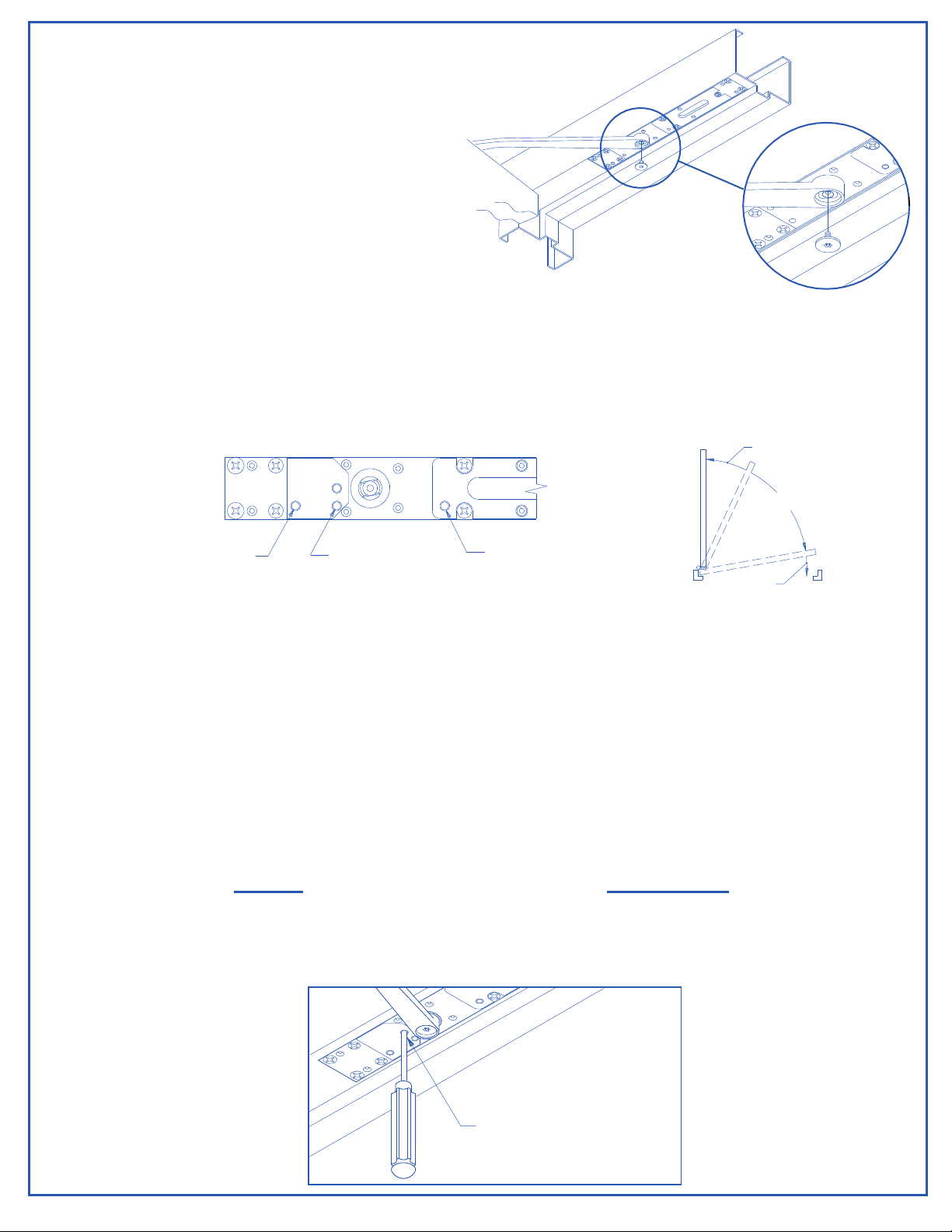
8. TO REGULATE CLOSING SPEED & BACKCHECK: Fig. 6
Do not use an abrupt
BACKCHECK setting, nor expect closer to act as a door stop!
9. FOR 2210DPS: SIGNAL RESPONSE POINT VERIFICATION
Only
If the switch is giving an "open" signal when the door is fully closed, follow steps 9D through 9F.
nearer
Fig. 7
ROODDNAHTFELROFROODDNAHTHGIRROF
YLTHGILSYREVYLTHGILSYREV
REMOVE SCREWDRIVER BEFORE ALLOWING DOOR TO MOVE.
Continued:
7D.With closer shaft now stationary, move the end
of the arm to shaft of closer. Slowly move door
so hole in arm lines up correctly with closer
shaft. Push arm up into position and insert
arm shaft screw, as shown in
See below
Use a 3/32” hex wrench to re-adjust MAIN & LATCH speed screws (closed in step 7A). Turn both MAIN
& LATCH speed screws 2 full turns counterclockwise. Open door and observe closing cycle. A normal closing
time from a 90° position is 5 to 7 seconds, equally divided between MAIN & LATCH speeds. If further adjustment
is required, turn regulating screws clockwise to SLOW door speed / counterclockwise to INCREASE door speed.
BACKCHECK is a feature that slows the speed of door at approximately 70°. To INCREASE force turn BACK-
CHECK screw clockwise. To REDUCE force turn BACKCHECK screw counterclockwise.
If door silencers are to be used, they should be installed prior to this step. Close the door slowly and note where
the switch response signal occurs. The factory setting should provide a signal response between 1/4" & 3/4" off
the stop for a 36" door.
if a different signaling point is necessary, perform steps 9A - 9C using a No. 3 Phillips screwdriver (5/16"
shank).
To adjust the signaling point for the door to the closed position:
9A.Open the door approximately 20°, or enough to access the signal adjustment hole in mounting plate
(See , below). Prevent door from moving during the adjustment. Insert the No. 3 Phillips screw-
driver into the signal adjustment hole to engage the trigger gear.
9B.
revirdwercsehtnruTrevirdwercsehtnruT
.yletelpmocesolcotroodehtwollA.C9
Check the signal activation point. If still too far from the "door closed" position, repeat steps 9A, 9B & 9C.
esiwkcolcretnuocesiwkcolc
Fig. 5
LATCH
SPEED
MAIN
SPEED
BACK
CHECK
Fig. 6
LATCH
SPEED
MAIN SPEED
BACKCHECK
Page 2
SIGNAL ADJUSTMENT
(No. 3 PHILLIPS SCREWDRIVER)
Fig. 7
9. FOR 2210DPS: SIGNAL RESPONSE POINT VERIFICATION ( CONT. )
farther
Fig. 7
ROODDNAHTFELROFROODDNAHTHGIRROF
YLTHGILSYREVYLTHGILSYREV
REMOVE SCREWDRIVER BEFORE ALLOWING DOOR TO MOVE
10. CLOSING POWER ADJUSTMENT:
Fig. 8
EROM:3122
counterclockwise
Do not
esiwkcolcretnuocEROM:4122
LESS
tonoDesiwkcolc
SSEL:5122
clockwise
Do not
11.
Fig. 9
To adjust the signaling point for the door from the closed position:
9D. Open the door approximately 20°, or enough to access the signal adjustment hole in mounting plate
(See , on previous page). Prevent door from moving during the adjustment. Insert the No. 3 Phillips
screwdriver into the signal adjustment hole to engage the trigger gear.
9E.
revirdwercsehtnruTrevirdwercsehtnruT
.yletelpmocesolcotroodehtwollA..F9
Check the signal activation point. If still too close to the "door closed" position, repeat steps 9D, 9E & 9F.
Depending on width of door, the 2210DPS has been ordered as one of
three sizes: 2213, 2214 or 2215. Determine closer size from either label on box or UL label on mounting
plate.
Adjustment can be made with a flat head screwdriver (see ). Adjustment range for each size is as
follows:
Closer is shipped at minimum closing power. If closing
power is required, turn adjusting screw , but
not more than 36 full turns. turn adjusting screw clockwise.
If power is required, turn adjusting screw ,
but not more than 18 full turns. If power is required, turn
adjusting screw , but not more than 18 full turns.
turn adjusting screw more than 18 full turns in either direction.
Closer is shipped at maximum closing power. If power is
required, turn adjusting screw , but not more than 36 full
Turns. turn adjusting screw counterclockwise.
Once proper operation has been verified, secure finish plates with No. 10-24 x 3/8" Torx security screws, as
shown in below.
esiwkcolcesiwkcolcretnuoc
Page 3
Fig. 8
Fig. 9
®

Other LCN Door Opening System manuals

LCN Benchmark III 9140 User manual

LCN

LCN Benchmark III 9140 User manual

LCN ST-2701 User manual

LCN

LCN ST-2701 User manual

LCN 4031 CUSH User manual

LCN

LCN 4031 CUSH User manual

LCN 4050 Track Series User manual

LCN

LCN 4050 Track Series User manual

LCN 1450 Series User manual

LCN

LCN 1450 Series User manual

LCN 4050 Series User manual

LCN

LCN 4050 Series User manual

LCN 4040SE User manual

LCN

LCN 4040SE User manual

LCN 3130 Series User manual

LCN

LCN 3130 Series User manual

LCN 1461 CUSH User manual

LCN

LCN 1461 CUSH User manual

LCN 8310-2410 User manual

LCN

LCN 8310-2410 User manual

LCN 3130-SEL Sentronic User manual

LCN

LCN 3130-SEL Sentronic User manual

LCN 4412 HSA Operation and maintenance manual

LCN

LCN 4412 HSA Operation and maintenance manual

LCN 8310-2420 User manual

LCN

LCN 8310-2420 User manual

LCN 4040XP User manual

LCN

LCN 4040XP User manual

LCN 4630CS User manual

LCN

LCN 4630CS User manual

LCN Benchmark III 9130 User manual

LCN

LCN Benchmark III 9130 User manual

LCN COMPACT 6400 Series User manual

LCN

LCN COMPACT 6400 Series User manual

LCN 4020 Series User manual

LCN

LCN 4020 Series User manual

LCN 4410ME Series User manual

LCN

LCN 4410ME Series User manual

LCN 4040XP User manual

LCN

LCN 4040XP User manual

LCN 1261 CUSH User manual

LCN

LCN 1261 CUSH User manual

LCN 4050 Series User manual

LCN

LCN 4050 Series User manual

LCN 3030 Series User manual

LCN

LCN 3030 Series User manual

LCN 4600 Series User manual

LCN

LCN 4600 Series User manual

Popular Door Opening System manuals by other brands

ENFORCER SM-4201-LQ manual

ENFORCER

ENFORCER SM-4201-LQ manual

UNIVERSAL HARDWARE UH4007 installation instructions

UNIVERSAL HARDWARE

UNIVERSAL HARDWARE UH4007 installation instructions

Dormakaba ED900 installation instructions

Dormakaba

Dormakaba ED900 installation instructions

DoorHan SHAFT-120 Installation and operating manual

DoorHan

DoorHan SHAFT-120 Installation and operating manual

G-U BKS B-7441 Series installation instructions

G-U

G-U BKS B-7441 Series installation instructions

Chamberlain MyQ Garage user guide

Chamberlain

Chamberlain MyQ Garage user guide

DITEC COM E installation manual

DITEC

DITEC COM E installation manual

Dorma G-SR EMR Fixing instructions

Dorma

Dorma G-SR EMR Fixing instructions

Richards-Wilcox DYNA-HOIST DC Series installation manual

Richards-Wilcox

Richards-Wilcox DYNA-HOIST DC Series installation manual

Eco FSA ECO SR-EFR BG TS-62 G Assembly instruction

Eco

Eco FSA ECO SR-EFR BG TS-62 G Assembly instruction

PDQ 5300 manual

PDQ

PDQ 5300 manual

Von Duprin WS9927 installation instructions

Von Duprin

Von Duprin WS9927 installation instructions

Assa Abloy Yale YM Series installation instructions

Assa Abloy

Assa Abloy Yale YM Series installation instructions

BFT FR95 Series manual

BFT

BFT FR95 Series manual

CDVI IPV1 manual

CDVI

CDVI IPV1 manual

hawa HAWA-Motronic 60 Installation and commissioning instructions

hawa

hawa HAWA-Motronic 60 Installation and commissioning instructions

SUGATSUNE LAMP FD50-H installation manual

SUGATSUNE

SUGATSUNE LAMP FD50-H installation manual

Langer & Laumann QKS6 user manual

Langer & Laumann

Langer & Laumann QKS6 user manual

manuals.online logo
manuals.online logoBrands
  • About & Mission
  • Contact us
  • Privacy Policy
  • Terms and Conditions

Copyright 2025 Manuals.Online. All Rights Reserved.