CONTENTS
3EN
TABLE OF CONTENTS
Operating instructions............................................................................. 5
Symbols................................................................................................5
Riding safety ......................................................................................... 6
CHAPTER 1 GENERAL INFORMATION ............................................7
Vehicle identification data .......................................................................8
Familiarizing with the vehicle...................................................................9
Specifications ......................................................................................10
Electrical system...................................................................................14
Recommended lubricants and liquids......................................................16
CHAPTER 2 OPERATION.................................................................17
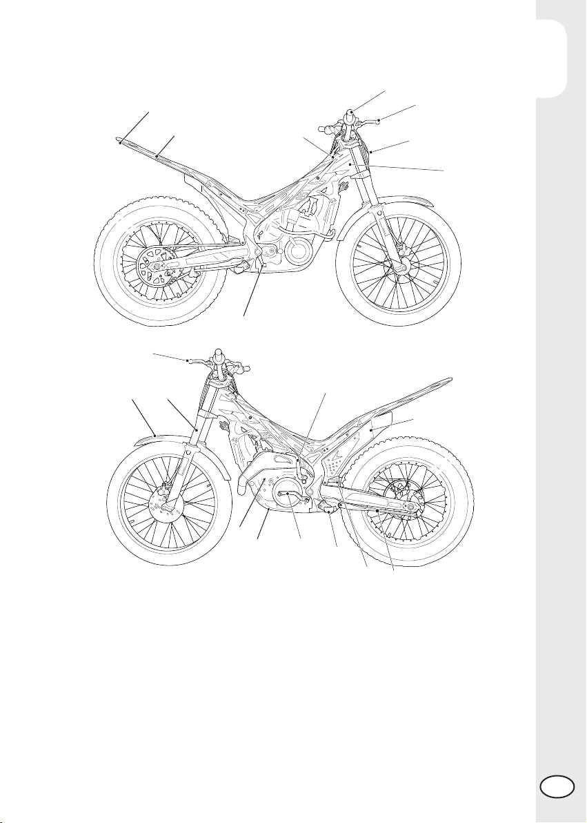
Main parts .......................................................................................... 18
Checks before and after use..................................................................22
Breaking in..........................................................................................22
Fuelling............................................................................................... 23
Startup................................................................................................ 24
Engine shut-down................................................................................. 24
CHAPTER 3 ADJUSTMENTS ............................................................25
Key to symbols.....................................................................................26
Brakes ................................................................................................26
Clutch.................................................................................................27
Adjustment of gas clearance..................................................................27
Accelerator .........................................................................................28
Handlebar adjustment .......................................................................... 28
Adjusting fork ......................................................................................28
Shock absorber....................................................................................29
Suspension adjustment according to the motorcyclist’s weight .................... 30
CHAPTER 4 CHECKS AND MAINTENANCE ...................................31
Key to symbols.....................................................................................32
Gear oil.............................................................................................. 32
Coolant ..............................................................................................33
Air filter ..............................................................................................35
Spark plug ..........................................................................................37
Carburetor ..........................................................................................38
Front Brake.......................................................................................... 40
Rear brake ..........................................................................................42


 Supplementary service manual")