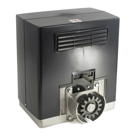
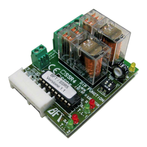
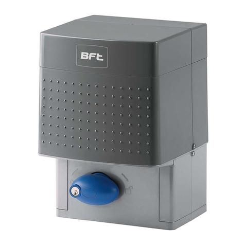
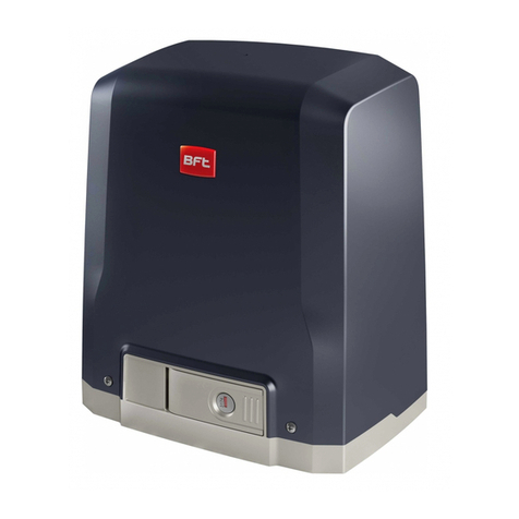
BFT URANO BT User manual

ISTRUZIONI D’USO E DI INSTALLAZIONE
INSTALLATION AND USER’S MANUAL
INSTRUCTIONSD’UTILISATIONETD’INSTALLATION
INSTALLATIONS-UND GEBRAUCHSANLEITUNG
INSTRUCCIONES DE USOY DE INSTALACION
INSTRUÇÕES DE USO E DE INSTALAÇÃO
D811431 ver. 05 15 -02-07
Via Lago di Vico, 44
36015 Schio (VI)
Tel.naz. 0445 696511
Tel.int. +39 0445 696533
Fax 0445 696522
Internet: www.bft.it
E-mail: [email protected]
URANO BT
I
GB
F
D
E
P
ATTUATORE PER CANCELLI SCORREVOLI A CREMAGLIERA
ACTUATOR FOR RACK SLIDING GATES
ACTIONNEUR POUR PORTAILS COULISSANTS A CREMAILLERE
ANTRIEB FÜR ZAHNSTANGEN-SCHIEBETORE
SERVOMOTOR PARA CANCELAS CORREDERAS DE CREMALLERA
ACCIONADOR PARA PORTÖES DE CORRER A CREMALLERA
8027908 2 4 8 7 9 4

2 - URANO BT Ver. 05
D811431_05

MANUALE D’USO ITALIANO
Nel ringraziarVi per la preferenza accordata a questo prodotto, la Ditta è
certa che da esso otterrete le prestazioni necessarie al Vostro uso. Leg-
gete attentamente l’opuscolo “Avvertenze” ed il “Libretto istruzioni” che
accompagnano questo prodotto in quanto forniscono importanti indicazioni
riguardanti la sicurezza, l’installazione, l’uso e la manutenzione. Questo
prodotto risponde alle norme riconosciute della tecnica e della disposizioni
relative alla sicurezza.
1) GENERALITÀ
L’attuatore URANO BT offre un’ampia versatilità d’installazione, grazie alla
posizioneestremamente bassa delpignone,alla compattezzadell’attuatore
e alla regolazione dell’altezza e profondità di cui dispone. É dotato di un
dispositivo elettronico antischiacciamento al fine di garantire la sicurezza.
La manovra manuale d’emergenza si effettua con estrema facilità tramite
una manopola a chiave personalizzata.
L’arrestoafinecorsaècontrollatodamicrointerruttorielettromeccanicioppure,
per zone molto fredde, da sensori di prossimità. La centralina di comando
può essere incorporata oppure montata su quadro separato.
2) SICUREZZA
Automazione, se installata ed utilizzata correttamente, soddisfa il grado di
sicurezza richiesto.Tuttavia è opportuno osservare alcune regole di com-
portamento per evitare inconvenienti accidentali.
• Non lasciare radiocomandi o altri dispositivi di comando alla portata dei
bambini onde evitare azionamenti involontari dell’automazione.
• Tenerebambini,personeecosefuoridalraggiod’azionedell’automazione,
in particolare durante il funzionamento.
• Non lasciare radiocomandi o altri dispositivi di comando alla portata dei
bambini onde evitare azionamenti involontari dell’automazione.
• Non contrastare volontariamente il movimento dell’anta.
• Non tentare di aprire manualmente il cancello se non è stato sbloccato
l’attuatore con l’apposita manopola di sblocco.
• Non modificare i componenti dell’automazione.
• Incasodimalfunzionamento, togliere l’alimentazione, attivarelo sblocco
di emergenza per consentire l’accesso e richiedere l’intervento di un
tecnico qualificato (installatore).
• Per ogni operazione di pulizia esterna, togliere l’alimentazione di rete.
• Tenere pulite le ottiche delle fotocellule ed i dispositivi di segnalazione
luminosa. Controllare che rami ed arbusti non disturbino i dispositivi di
sicurezza (fotocellule).
• Per qualsiasi intervento diretto all’automazione, avvalersi di personale
qualificato (installatore).
• Annualmente far controllare l’automazione da personale qualificato.
• Esaminare frequentemente che l’installazione non presenti segni di
usura o danni a cavi, a molle e a supporti.Se si ritenesse necessario un
intervento di manutenzione, non utilizzare l’automazione.
• L’attivazionedellosbloccomanopolepotrebbecausaremovimentiincon-
trollati della porta se in presenza di guasti o di condizioni di squilibrio.
3) SBLOCCO MANUALE
Lo sblocco manuale o di emergenza va attivato quando si deve aprire
manualmente il cancello ed in ogni caso di non funzionamento o funziona-
mento anomalo dell’automazione. Per eseguire la manovra di emergenza,
bisogna:
• Inserirelachiavepersonalizzatanellaserratura,ruotarelachiaveinsenso
antiorario per 90°.
• Impugnare la manopola di sblocco e ruotarla in senso orario (fig.1) fino
al suo arresto.In questo modo si rende folle il pignone permettendo così,
l’apertura manuale del cancello.
• Spingere manualmente l’anta del cancello accompagnandola per tutta la
sua corsa.
Attenzione: Non spingere violentemente l’anta del cancello, ma
accompagnarla per tutta la sua corsa.
La chiave non si può togliere dalla serratura fino a quando la manopola
non viene riportata nella posizione iniziale (azionamento motorizzato).
• Per ripristinare il comando motorizzato, ruotare la manopola in senso
antiorario per tutta la sua corsa, riportare la chiave in posizione di chiu-
sura quindi togliere la chiave e riporla in un luogo sicuro e conosciuto
agli interessati.
4) MANUTENZIONE E DEMOLIZIONE
Lamanutenzionedell’impiantovafatta eseguireregolarmenteda parte
di personale qualificato. I materiali costituenti l’apparecchiatura e il suo
imballo vanno smaltiti secondo le norme vigenti.
AVVERTENZE
Ilbuonfunzionamentodell’operatoreègarantitosolosevengonorispettate
i dati riportati in questo manuale. La ditta non risponde dei danni causati
dall’inosservanza delle norme di installazione e delle indicazioni riportate
in questo manuale.
Ledescrizionieleillustrazionidelpresentemanualenonsonoimpegnative.
Lasciando inalterate le caratteristiche essenziali del prodotto, la Ditta si
riservadiapportareinqualunquemomentolemodifichecheessaritienecon-
venientipermiglioraretecnicamente,costruttivamenteecommercialmente
il prodotto, senza impegnarsi ad aggiornare la presente pubblicazione.
Fig. 1
1
2
OPEN
CLOSE
URANO BT Ver. 05 - 3
D811431_05

USER’S MANUAL
ENGLISH
Thank you for buying this product, our company is sure that you will be more
than satisfied with the product’s performance.The product is supplied with
a “Warnings” leaflet and an “Instruction booklet”. These should both be
read carefully as they provide important information about safety, installa-
tion, operation and maintenance.This product complies with the recognised
technicalstandardsandsafetyregulations.Wedeclare that this product is in
conformity with the following European Directives:89/336/EEC, 73/23/EEC,
98/37/EEC (and subsequent amendments).
1) GENERAL OUTLINE
The URANO BT actuator offers ample installation versatility, thanks to the
extremely low position of the pinion, the compactness of the actuator and to
theheightanddepthwhichcanbeveryeasilyadjusted.Itisequippedwithan
antisquash electronic device, which ensures utmost safety.The emergency
manual release can be activated very easily by means of a knob featuring
a personalised key.
Thegatestopiscontrolledbyelectromechanicalend-of-strokemicroswitches
or, for very cold areas, by proximity sensors.
The control board can be built-in or installed onto a separate cabinet.
2) SAFETY
If correctly installed and used, this automation device satisfies the required
safety level standards. However, it is advisable to observe some practical
rules in order to avoid accidental problems.
• Keep radio control or other control devices out of children’s reach, in
order to avoid any unintentional automation activation.
• Keep children, persons and things outside the automation working area,
particularly during operation.
• Keep radio control or other control devices out of children’s reach, in
order to avoid any unintentional automation activation.
• Do not intentionally oppose the leaf movement.
• Do not attempt to open the gate by hand, if the actuator has not been
released by means of the appropriate release knob.
• Do not modify the automation components.
• In case of malfunction, disconnect the power supply, activate the emer-
gency release to gain access to the actuator and request the assistance
of a qualified technician (installer).
• Before proceeding to any external cleaning operation, disconnect the
mains powers supply.
• Keep the photocell optical components and luminous signal indication
devicesclean.Checkthatthesafetydevices(photocells)arenotobscured
by branches or shrubs.
• Foranydirectassistancetotheautomationsystem,requesttheassistance
of a qualified technician (installer).
• Have qualified personnel check the automation system once a year.
• Inspect the installation frequently to check that there are no signs of
wear or damage to the springs or supports. If any maintenance work is
deemed necessary, do not use the operator.
• Theactivationofhandlereleasecouldcauseuncontrolleddoormovements
if any faulty or unbalanced conditions are present.
3) MANUAL RELEASE
The manual or emergency release should only be activated when the gate
has to be opened manually or whenever the automation is not correctly or
totally functioning.
To carry out the emergency manoeuvre, proceed as follows:
• Insert the personalised key into the lock and turn it anticlockwise by 90°.
• Turn the release knob clockwise (fig.1) as far as it will go.The pinion will
therefore become idle and the gate can then be opened manually.
• Push the leaf of the gate all the way down to the end-of-stroke.
Warning: do not push the gate leaf roughly, but move it gently all
along its stroke.
The key can be removed from the lock only after the knob has been
moved back to its initial position (motor-driven operation)
• Tore-activatemotor-drivencontrol,turntheknobanticlockwiseasfarasit
will go.Move the key back to its closing position, remove it and then store
it in a safe place, which is known to anyone who may need the knob.
4) MAINTENANCE AND DEMOLITION
The maintenance of the system should only be carried out by qualified
personnel regularly. The materials making up the set and its packing must
be disposed of according to the regulations in force.
WARNINGS
Correctcontrolleroperationisonlyensuredwhenthedatacontainedin
thepresentmanualareobserved.Thecompanyisnottobeheldrespon-
sible for any damage resulting from failure to observe the installation
standards and the instructions contained in the present manual.
The descriptions and illustrations contained in the present manual are
not binding.The Company reserves the right to make any alterations
deemed appropriate for the technical, manufacturing and commercial
improvement of the product, while leaving the essential product fea-
tures unchanged, at any time and without undertaking to update the
present publication.
Fig. 1
1
2
OPEN
CLOSE
4 - URANO BT Ver. 05
D811431_05

MANUEL D’UTILISATION FRANÇAIS
Nous vous remercions pour avoir choisi ce produit.Nous sommes certains
qu’il vous offrira les performances que vous souhaitez.Lisez attentivement
la brochure “Avertissements” et le “Manuel d’instructions” qui accompa-
gnent ce produit, puisqu’ils fournissent d’importantes indications concernant
la sécurité, l’installation, l’utilisation et l’entretien. Ce produit est conforme aux
règles reconnues de la technique et aux dispositions de sécurité. Nous certi-
fions sa conformité avec les directives européennes suivantes: 89/336/CEE,
73/23/CEE, 98/37/CEE (et modifications successives).
1) GENERALITES
L’automatisme URANO BT offre de vastes possibilités d’installation, grâce
au pignon situé en position très basse, à la compacité de l’actionneur et
au réglage de la hauteur et de la profondeur dont il dispose. Il est doté
d’un dispositif électronique anti-écrasement afin d’assurer la plus grande
sécurité. La manoeuvre manuelle d’urgence se fait très facilement à l’aide
d’une poignée à clé personnalisée.
L’arrêt à la fin de course est commandé par des microinterrupteurs
électromécaniques ou bien, pour des zones très froides, par des capteurs
de proximité.La centrale de commande peut être incorporée ou montée
sur une boîte à part.
2) SECURITE
La motorisation, si installée et utilisée correctement, est conforme au degré
de sécurité demandé. Il est toutefois conseillé de respecter ces quelques
règles de conduite afin d’éviter tout inconvénient ou accident.
• Nepaslaisserlesradiocommandesoud’autresdispositifsdecommande
à la portée des enfants, afin d’éviter des actionnements involontaires de
la motorisation.
• Tenir les enfants, les personnes et les choses hors du rayon d’action de
la motorisation, particulièrement pendant le fonctionnement.
• Nepaslaisserlesradiocommandesoud’autresdispositifsdecommande
à la portée des enfants, afin d’éviter des actionnements involontaires de
la motorisation.
• Ne pas contraster volontairement le mouvement du portail.
• Ne pas chercher à ouvrir manuellement le portail si l’actionneur n’a pas
été débloqué avec la poignée de déblocage spéciale.
• Ne pas modifier les composants de la motorisation.
• En cas de mauvais fonctionnement, couper l’alimentation, activer le dé-
blocage d’urgence afin de permettre l’accès et demander l’intervention
d’un technicien qualifié (installateur).
• Pour toute opération de nettoyage extérieur, couper l’alimentation de
ligne et, si présent, au moins un pôle des batteries.
• Nettoyer les optiques des cellules photoélectriques et les dispositifs de
signalisationlumineuse.S’assurerquedesbranchesoudesarbustesne
dérangent pas les dispositifs de sécurité (cellules photoélectriques).
• Pour toute intervention directe sur la motorisation, s’adresser à du per-
sonnel qualifié (installateur).
•
Chaque année, faire contrôler la motorisation par du personnel qualifié.
• Examiner régulièrement que l’installation ne présente pas de signes
d’usure ou de dommages aux câbles, aux ressorts et aux supports. Ne
pas utiliser l’automation si une intervention d’entretien est nécessaire.
• L’activation du déblocage des poignées pourrait provoquer des mouve-
ments incontrôlés de la porte en présence de pannes ou de conditions
de déséquilibre.
3) DEBLOCAGE MANUEL
Ledéblocagemanuel ou d’urgence doit êtreactivési on doit ouvrir leportail
manuellement et dans tous les cas de non fonctionnement ou de mauvais
fonctionnement de l’automatisme. Pour effectuer la manoeuvre d’urgence,
il faut:
• Enfoncer la clé personnalisée dans la serrure, tourner la clé de 90° dans
le sens contraire à celui des aiguilles d’une montre.
• Saisir la poignée de déblocage et la tourner dans le sens des aiguilles
d’une montre (fig. 1) jusqu’à son arrêt. Le pignon devient ainsi fou, ce
qui permet l’ouverture du portail.
• Pousser le vantail du portail manuellement, en l’accompagnant pour
toute sa course.
Attention:Ne pas pousser le vantail du portail trop énergiquement, mais
l’accompagner pour toute sa course.
La clé ne peut pas être enlevée de la serrure tant que la poignée n’est
pas replacée dans sa position initiale (actionnement motorisé).
• Pour rétablir la commande motoriste, tourner la poignée dans le sens
contraireàceluidesaiguillesd’unemontrepourtoutesacourse,replacer
la clé dans la position de fermeture, puis enlever la clé et la ranger dans
un lieu sûr et connu par les personnes concernées.
4) ENTRETIEN ET DEMOLITION
L’entretiendel’installationdoitêtreeffectuérégulièrementdelapartde
personnelqualifié.Lesmatériauxconstituantl’appareillageetsonemballage
doivent être mis au rebut conformément aux normes en vigueur.
AVERTISSEMENTS
Lebonfonctionnementdel’actionneur n’estassuréque silesdonnées
fournies dans ce manuel sont respectées. Le constructeur ne répond
pas pour les dommages provoqués par le non respect des normes
d’installation et des indications fournies dans ce manuel.
Les descriptions et les figures de ce manuel n’engagent pas le con-
structeur. En laissant inaltérées les caractéristiques essentielles du
produit, la Société se réserve le droit d’apporter à n’importe quel
moment les modifications qu’elle juge opportunes pour améliorer le
produitdupointdevuetechnique,commercialetdeconstruction,sans
s’engager à mettre à jour cette publication.
Fig. 1
1
2
OPEN
CLOSE
URANO BT Ver. 05 - 5
D811431_05

BEDIENUNGSANLEITUNG
DEUTSCH
WirdankenIhnen,daßSiesichfürdieseAnlageentschiedenhaben.Ganzsicher
wirdsiemitihrenLeistungenIhrenAnsprüchenvollaufgerechtwerden.Lesen
SieaufmerksamdieBroschüre“Hinweisen“unddie“Gebrauchsanweisung“
durch,diedemProduktbeiliegen.SieenthaltenwichtigeHinweisezurSicherheit,
Installation,BedienungundWartungderAnlage.DiesesProduktgenügtdenan-
erkanntentechnischenRegelnundSicherheitsbestimmungen.Wirbestätigen,
daß es mit folgenden Europäischen Richtlinien übereinstimmt:89/336/EWG,
73/23/EWG, 98/37/ EWG (und ihren nachfolgende Änderungen).
1) ÜBERSICHT
Der Torantrieb URANO BT bietet wegen seines extrem niedrig gelegenen
Ritzels, seiner kompakten Bauweise und der Verstellbarkeit in Höhe und
Tiefe eine große Anzahl Installationsmöglichkeiten. Sein elektronischer
QuetschschutzgewährleistetdieSicherheitderAnlage.ImNotfallläßtsiesich
kinderleicht mit einem Handgriff bedienen, der nur mit einem persönlichen
Schlüssel entsperrt werden kann.
DerEndanschlagsbetriebwirdvonelektromechanischenMikroschalternoder
- in besonders kalten Gegenden - von Näherungssensoren gesteuert.
Die Steuerung ist entweder bereits integriert oder wird in einem separaten
Kasten montiert.
2) SICHERHEIT
Die Anlage erfüllt bei richtiger Installation und Bedienung die erforderlichen
Sicherheitsstandards.Trotzdem ist es sinnvoll, einige Verhaltensmaßregeln
zu beachten, um unvorhergesehene Zwischenfälle auszuschließen.
• KeineFernbedienungenoderandereSteuerungsvorrichtungeninReich-
weite von Kindern liegen lassen. Sie könnten die Anlage ungewollt in
Gang setzen.
• Kinder,ErwachseneundSachwertesolltensichaußerhalbdesWirkradius
der Anlage befinden, besonders während des Betriebes.
• KeineFernbedienungenoderandereSteuerungsvorrichtungeninReich-
weite von Kindern liegen lassen. Sie könnten die Anlage ungewollt in
Gang setzen.
• Der Flügelbewegung nicht willentlich Kraft entgegensetzen.
• Nicht versuchen, dasTor von Hand zu öffnen, wenn nicht vorher der An-
trieb mit dem entsprechenden Entriegelungshandgriff entsperrt wurde.
• Keine Umbauten an Anlagenkomponenten vornehmen.
• Bei Betriebsstörungen die Stromversorgung unterbrechen, durch Be-
tätigung der Notfallentsperrung den Zugang ermöglichen und einen
fachkundigenTechniker (Installateur) hinzuziehen.
• Vor jeder Außenreinigung die Stromversorgung unterbrechen und - falls
vorhanden - zumindest einen Batteriepol abklemmen.
• HaltenSiedieOptikender Fotozellenund dieLeuchtsignalvorrichtungen
sauber.PrüfenSie,obÄsteoderGesträuch dieSicherheitsvorrichtungen
beeinträchtigen können (Fotozellen).
• Wenn eine Arbeit unmittelbar an der Anlage erforderlich ist, wenden Sie
sich hierzu an fachkundiges Personal (Installateur).
• Die Anlage muß einmal jährlich von Fachpersonal kontrolliert werden.
• Esmußhäufigeruntersuchtwerden,obdieAnlageVerschleißspurenoder
Schäden an Kabeln, Federn und Tragelementen aufweist. Entscheidet
man sich für Instandsetzungsmaßnahmen, darf der Antrieb nicht mehr
verwendet werden.
• DieBetätigungderEntriegelungderHandgriffekannimFallevonSchäden
oderGleichgewichtsstörungenungewünschteBewegungendesToreszur
Folge haben.
3) HANDENTSPERRUNG
DieHand- oder Notfallentsperrungwird betätigt,wenndasTor manuellgeöf-
fnet werden muß, also bei Ausfall oder Fehlfunktionen der automatischen
Toranlage.Die Notfallbedienung läuft wie folgt ab:
• Denpersonalisierten Schlüsselindas Schloßstecken undum90° gegen
den Uhrzeigersinn drehen.
• EntsperrgriffbiszumAnschlagimUhrzeigersinndrehen(Fig.1).Dadurch
wird der Ritzel gelöst und das Tor läßt sich von Hand öffnen.
• Nun den Torflügel beim Anschieben auf der gesamten Strecke nicht
loslassen.
Vorsicht: Schieben Sie den Torflügel nicht mit Gewalt an, sondern
begleiten Sie ihn während seines gesamten Laufes.
Der Schlüssel kann erst aus dem Schloß gezogen werden, wenn der
Handgriff in seine Ausgangsstellung (Motorantrieb) zurückgebracht
wird.
• Um den Motorbetrieb wieder aufzunehmen, den Handgriff ganz gegen
den Uhrzeigersinn drehen, den Schlüssel in Verschlußposition bringen
und abziehen. Er ist an einem sicheren Ort aufzubewahren, der allen
Beteiligten bekannt ist.
4) INSTANDHALTUNG UND VERSCHROTTUNG
Die Anlagenwartung ist regelmäßig von Fachleuten vorzunehmen.Die
Materialien, aus denen die Apparatur besteht und ihre Verpackung sind
vorschriftsmäßig zu entsorgen.
HINWEISE
DereinwandfreieBetriebdesAntriebesistnurdanngarantiert,wenndie
Angaben aus diesem Handbuch beachtet werden.Der Hersteller haftet
nichtfürSchäden,diedurchMißachtungderInstallationsanweisungen
und der Angaben aus diesem Handbuch entstehen.
Die Beschreibungen und bildlichen Darstellungen in diesem Hand-
buch sind unverbindlich. Der Hersteller behält sich - ohne auch zur
Aktualisierung dieser Unterlagen verpflichtet zu sein - jederzeit vor,
Änderungen vornehmen, wenn er diese für technische oder bauliche
Verbesserungen als notwendig erachtet und die wesentlichen Produk-
teigenschaften unverändert bleiben.
Fig. 1
1
2
OPEN
CLOSE
6 - URANO BT Ver. 05
D811431_05

MANUAL DE USO ESPAÑOL
Al agradecerle la preferencia que ha manifestado por este producto, la
empresa está segura de que de él obtendrá las prestaciones necesarias
parasusexigencias.Leaatentamenteelfolleto“Advertencias”yel“Manual
de instrucciones” que acompañan a este producto, pues proporcionan
importantesindicacionesreferentes ala seguridad, lainstalación, eluso yel
mantenimientodel mismo.Esteproductocumple losrequisitosestablecidos
por las normas reconocidas de la técnica y las disposiciones relativas a la
seguridad.Confirmamos su conformidad con las siguientes directivas euro-
peas: 89/336/CEE, 73/23/CEE, 98/37/ CEE (y modificaciones sucesivas).
1) DATOS GENERALES
El servomotor URANO BT ofrece una amplia versatilidad de instalación,
gracias a la posición extremadamente baja del piñón, a la consistencia del
servomotor y ala regulaciónde la altura y dela profundidad deque dispone.
Está dotado de un dispositivo electrónico antiaplastamiento para garantizar
la seguridad. La maniobra manual de emergencia se efectúa con extrema
facilidad mediante una manecilla con llave personalizada.
La parada de fin de carrera es controlada por medio de microinterruptores
electromecánicosobien,encasodezonasmuyfrías,pormediodesensores
de proximidad.El cuadro de mandos puede incorporarse en el operador o
montarse en una caja separada.
2) SEGURIDAD
El automatismo, si se instala y utiliza correctamente, satisface el grado de
seguridad requerido.Sin embargo, es conveniente observar algunas reglas
de comportamiento para evitar inconvenientes accidentales.
• No dejar radiomandos u otros dispositivos de mando al alcance de los
niños, para evitar el accionamiento involuntario del automatismo.
• Mantener a niños, personas y cosas fuera del campo de acción del
automatismo, especialmente durante su funcionamiento.
• No dejar radiomandos u otros dispositivos de mando al alcance de los
niños, para evitar el accionamiento involuntario del automatismo.
• No contrastar voluntariamente el movimiento de la hoja.
• Nointentarabrirmanualmentelacancelasiantesnosehadesbloqueado
el servomotor con la manecilla de desbloqueo.
• No modificar los componentes del automatismo.
• En caso de mal funcionamiento, cortar el suministro de corriente, activar
el mecanismo de desbloqueo de emergencia para consentir el acceso
y solicitar la intervención de un técnico cualificado (instalador).
• Antes de realizar cualquier operación de limpieza externa, cortar el
suministro de corriente.
• Mantener limpias las lentes de las fotocélulas y los dispositivos de se-
ñalización luminosa. Controlar que ramas o arbustos no interfieran con
los dispositivos de seguridad (fotocélulas).
• Siresultanecesarioefectuarunaintervencióndirectaenelautomatismo,
llamar a personal cualificado (instalador).
• Una vez al año, es preciso hacer controlar el automatismo por personal
cualificado.
• Controle frecuentemente que la instalación no presente señales de
desgaste o daños en cables, en muelles y en soportes.Si se considera
necesaria una intervención de mantenimiento, no utilice el automati-
smo.
• La activación del sistema de desbloqueo de las manillas podría causar
movimientos incontrolados de la puerta en presencia de averías o de
condiciones de desequilibrio.
3) DESBLOQUEO MANUAL
El mecanismo de desbloqueo manual o de emergencia debe activarse
cuando se tiene que abrir manualmente la cancela y en todo caso de no
funcionamiento o funcionamiento anómalo del automatismo. Para ejecutar
la maniobra de emergencia, hay que realizar lo siguiente:
• Introducir la llave personalizada en la cerradura y girarla 90° en sentido
contrario a las agujas del reloj.
• Empuñarla manecilladedesbloqueoy girarlaenel sentidodelasagujas
del reloj (fig. 1), hasta su bloqueo. De esta manera, se deja suelto el
piñón, permitiendo la apertura manual de la cancela.
• Empujar manualmente la hoja de la cancela, acompañándola por toda
su carrera.
Atención: La hoja de la cancela debe acompañarse por toda su carrera
y no debe empujarse violentamente.
• La llave debe permanecer en la cerradura hasta que la manecilla se
coloque en la posición inicial (accionamiento motorizado).
• Pararestablecerelaccionamientomotorizado,hayquegirarlamanecilla
en sentido contrario a las agujas del reloj por toda su carrera, poner la
llave de nuevo en posición de cierre y, a continuación, quitar la llave y
guardarla en un lugar seguro y conocido por los interesados.
4) MANTENIMIENTOY DEMOLICION
Elmantenimientode lainstalacióndebe serrealizado,con regularidad,
por personal cualificado. Los materiales que constituyen el equipo y su
embalaje deben eliminarse de conformidad con las normas vigentes.
ADVERTENCIAS
El buen funcionamiento del operador resulta garantizado únicamente
si se respetan los datos contenidos en este manual de instrucciones.
La empresa no responde de los daños causados por el incumplimien-
to de las normas de instalación y de las indicaciones contenidas en
este manual.
Las descripciones y las ilustraciones del presente manual tienen un
carácter puramente indicativo.Dejando inalteradas las características
esencialesdelproducto,laEmpresasereservalaposibilidaddeaportar,
encualquiermomento,lasmodificacionesqueconsidereconvenientes
para mejorar técnica, constructiva y comercialmente el producto, sin
la obligación de poner al día esta publicación.
Fig. 1
1
2
OPEN
CLOSE
URANO BT Ver. 05 - 7
D811431_05

MANUAL PARA DE USO
PORTUGUÊS
Agradecendolhe pela preferência dada a este produto, a Empresa tem a
certeza que do mesmo obterá as prestações necessárias para o uso que
entendefazer.Leiaatentamenteoopúsculo“Recomendações”eo“Manual
de instruções” que o acompanham, pois que esses fornecem indicações
importantes respeitantes a segurança, a instalação, o uso e a manutenção.
Esteprodutoestáemconformidadecomasnormasreconhecidaspelatécnica
e pelas disposições relativas à segurança. Confirmamos que o mesmo está
em conformidade com as seguintes directivas europeias: 89/336/CEE, 73/23/
CEE,98/37/ CEE (e modificações sucessivas).
1) GENERALIDADES
O accionador URANO BT oferece uma ampla versatilidade de instalação,
graçasàposiçãoextremamentebaixadopinhão,àcompacidadedoacciona-
doreàregulaçãodaalturae profundidade de que dispõe.Está equipado de
umdispositivoelectrónico anti-esmagamentoquevisagarantirasegurança.
Amanobramanualdeemergênciaefectua-secomextremafacilidadeatravés
dum manípulo com chave personalizada.
Aparagemnofinaldecursoécontroladapormicrointerruptoreselectromecâ-
nicos ou então, nas zonas muito frias, por sensores de proximidade.
O quadro de comandos pode ser incorporado ou montado em uma caixa
separada.
2) SEGURANÇA
Se a automatização é instalada e utilizada correctamente, satisfaz o grau
de segurança exigido. Todavia, é oportuno respeitar algumas regras de
comportamento para evitar problemas acidentais.
• Não deixe radiocomandos ou outros dispositivos de comando ao alcance
das crianças, para evitar accionamentos involuntários da automatização.
• Mantenha crianças, pessoas e objectos fora do raio de acção da auto-
matização, especialmente durante o funcionamento.
• Não deixe radiocomandos ou outros dispositivos de comando ao alcance
das crianças, para evitar accionamentos involuntários da automatização.
• Não impeça voluntariamente o movimento da folha.
• Nãotentedeabrirmanualmenteoportãoseoaccionador,comespecífico
manípulo de desbloqueio, não tiver sido desbloqueado.
• Não modifique os componentes da automatização.
• Emcasode mau funcionamento,interrompa aalimentação, activeo des-
bloqueio de emergência para consentir o acesso e peça a intervenção
de um técnico qualificado (instalador).
• Para qualquer operação de limpeza externa, interrompa a alimentação
de rede.
• Mantenhalimpasasópticasdasfotocélulaseosdispositivosdesinalização
luminosa.Controle que ramos e arbustos não disturbem os dispositivos
de segurança (fotocélulas).
• Paraqualquer intervençãodirectanaautomatização,sirva-sedepessoal
qualificado (instalador).
• Faça controlar anualmente a automatização por pessoal qualificado.
•Examinarfrequentementequeainstalaçãonãoapresentesinaisdedesga-
steou danos nos cabos, molas e suportes.Não utilizar a automatização,
se achar que é necessário efectuar uma intervenção de manutenção.
• A activação do desbloqueio dos puxadores poderia causar movimentos
incontroláveis da porta em presença de avarias ou de condições de
desequilíbrio.
3) DESBLOQUEIO MANUAL
Odesbloqueio manualou de emergência deve seractivadoquandosedeve
abriroportãomanualmentee,emtodosaquelescasosdenãofuncionamento
ou de funcionamento anómalo da automatização.Para efectuar a manobra
de emergência, é preciso:
• Introduzir a chave personalizada na fechadura, girá-la no sentido anti-
horário por 90°.
• Pegar no manípulo de desbloqueio e girá-lo no sentido horário (fig.1)
até a sua paragem. Deste modo, torna-se livre o pinhão permitindo-se
assim, a abertura manual do portão.
• Empurrar manualmente a folha do portão acompanhando-a por todo o
seu percurso.
Atenção:Nãoempurrarcomviolênciaafolhadoportão,masacompanhá-
la por todo o seu percurso.
A chave não pode ser extraída da fechadura até quando o manípulo não
é recolocado na posição inicial (accionamento motorizado).
• Para restabelecer o comando motorizado, girar o manípulo no sentido
anti-horário por todo o seu percurso, voltar a colocar a chave na posição
defecho extraira chave e guardá-lanumlugar seguro e conhecidopelos
interessados.
4) MANUTENÇÃO E DEMOLIÇÃO
A manutenção da instalação deve ser executada periodicamente por
pessoal qualificado.Os materiais que constituem a aparelhagem e a sua
embalagem devem ser eliminados de acordo com a legislação vigente.
AVISOS
O bom funcionamento do operador é garantido, somente se forem
respeitadososdadoscontidosnestemanual.Aempresanãoresponde
por danos provocados pela inobservância das normas de instalação
e das indicações contidas neste manual.
As descrições e as ilustrações deste manual não constituem um
compromisso. Mantendo inalteradas as características essenciais
do produto, a Empresa reservase o direito de efectuar em qualquer
momento as modificações que julgar convenientes para melhorar as
características técnicas, de construção e comerciais do produto, sem
comprometerse em actualizar esta publicação.
Fig. 1
1
2
OPEN
CLOSE
8 - URANO BT Ver. 05
D811431_05

MANUALE PER L’INSTALLAZIONE ITALIANO
Nel ringraziarVi per la preferenza accordata a questo prodotto, la Ditta è
certa che da esso otterrete le prestazioni necessarie al Vostro uso. Leg-
gete attentamente l’opuscolo “Avvertenze” ed il “Libretto istruzioni” che
accompagnano questo prodotto in quanto forniscono importanti indicazioni
riguardanti la sicurezza, l’installazione, l’uso e la manutenzione. Questo
prodotto risponde alle norme riconosciute della tecnica e della disposizioni
relative alla sicurezza.Confermiamo che è conforme alle seguenti direttive
europee: 89/336/CEE, 73/23/CEE (e loro modifiche successive).
1) GENERALITÀ
L’attuatore URANO BT offre un’ampia versatilità d’installazione, grazie alla
posizione estremamente bassa del pignone, alla compattezza dell’attua-
tore e alla regolazione dell’altezza e profondità di cui dispone. Il limitatore
di coppia, regolabile, garantisce la sicurezza contro lo schiacciamento. La
manovra manuale d’emergenza si effettua con estrema facilità tramite una
manopola a chiave personalizzata.
L’arresto a fine corsa è controllato da microinterruttori elettromeccanici
oppure, per zone molto fredde, da sensori di prossimità.
Il quadro comandi può essere incorporato oppure montato su scatola separata.
Il motoriduttore (fig.1) è costituito da :
M Motore
R Riduttore a vite senza fine - ruota elicoidale
SGruppo finecorsa elettromeccanico oppure sensore di prossimità
P Pignone con meccanismo di sblocco
C Quadro di comando
B2 batterie tampone (BT BAT 2)
2) SICUREZZA GENERALE
ATTENZIONE!
Una installazione errata o un uso improprio del prodotto, può creare
danni a persone, animali o cose.
• Leggete attentamente l’opuscolo ”Avvertenze” ed il ”Libretto istruzioni”
cheaccompagnanoquestoprodotto,inquantofornisconoImportantiindi-
cazioni riguardanti la sicurezza, l’installazione, l’uso e la manutenzione.
• Smaltireimaterialidiimballo(plastica,cartone,polistirolo,ecc.) secondo
quantoprevistodallenormevigenti.Nonlasciarebustedinylonepolistirolo
a portata dei bambini.
• Conservare le istruzioni per allegarle al fascicolo tecnico e per consul-
tazioni future.
• Questoprodottoèstatoprogettatoecostruitoesclusivamenteperl’utilizzo
indicato in questa documentazione.
Usi non indicati in questa documentazione potrebbero essere fonte di
danni al prodotto e fonte di pericolo.
• La Ditta declina qualsiasi responsabilità derivante dall’uso improprio o
diverso da quello per cui è destinato ed indicato nella presente docu-
mentazione.
• Non installare il prodotto in atmosfera esplosiva.
• Gli elementi costruttivi della macchina devono essere in accordo con le
seguenti Direttive Europee: 89/336/CEE, 73/23/CEE e loro modifiche
successive.Per tutti i Paesi extra CEE, oltre alle norme nazionali vigenti,
per un buon livello di sicurezza è opportuno rispettare anche le norme
sopracitate.
• La Ditta declina qualsiasi responsabilità dall’inosservanza della Buona
Tecnica nella costruzione delle chiusure (porte, cancelli, ecc.), nonché
dalle deformazioni che potrebbero verificarsi durante l’uso.
•
L’installazionedeveessereinaccordoconquantoprevistodalleDirettiveEu-
ropee: 89/336/CEE, 73/23/CEE,98/37 CEE e loro modifiche successive.
• Toglierel’alimentazioneelettrica,primadiqualsiasiinterventosull’impianto.
Scollegare anche eventuali batterie tampone se presenti.
• Prevederesullaretedialimentazionedell’automazione,uninterruttoreoun
magnetotermico onnipolare con distanza di apertura dei contatti uguale
o superiore a 3,5 mm.
• Verificare che a monte della rete di alimentazione, vi sia un interruttore
differenziale con soglia da 0.03A.
• Verificarese l’impianto di terra è realizzato correttamente:collegare tutte
lepartimetallichedellachiusura(porte,cancelli,ecc.)etuttiicomponenti
dell’impianto provvisti di morsetto di terra.
• Applicare tutti i dispositivi di sicurezza (fotocellule, coste sensibili, ecc.)
necessari a proteggere l’area da pericoli di schiacciamento, convoglia-
mento, cesoiamento.
• Applicarealmenoundispositivodisegnalazioneluminosa(lampeggiante)
in posizione visibile, fissare alla struttura un cartello di Attenzione.
• La Ditta declina ogni responsabilità ai fini della sicurezza e del buon
funzionamento dell’automazione se vengono impiegati componenti di
altri produttori.
• Usare esclusivamente parti originali per qualsiasi manutenzione o ripa-
razione.
• Non eseguire alcuna modifica ai componenti dell’automazione se non
espressamente autorizzata dalla Ditta.
• Istruirel’utilizzatoredell’impiantoperquantoriguardaisistemidicomando
applicati e l’esecuzione dell’apertura manuale in caso di emergenza.
• Non permettere a persone e bambini di sostare nell’area d’azione del-
l’automazione.
• Non lasciare radiocomandi o altri dispositivi di comando alla portata dei
bambini onde evitare azionamenti involontari dell’automazione.
• L’utilizzatore deve evitare qualsiasi tentativo di intervento o riparazione
dell’automazione e rivolgersi solo a personale qualificato.
• Tutto quello che non è espressamente previsto in queste istruzioni, non
è permesso.
• L’installazione deve essere fatta utilizzando dispositivi di sicurezza e
comandi conformi alla EN 12978.
• Controllare che il range dichiarato di temperatura sia compatibile con il
luogo destinato all’installazione dell’automazione.
• Il motore non può essere installato su cancelli che incorporano porte (a
meno che la motorizzazione non possa funzionare a porta aperta).
• Assicurarsi che sia evitato lo schiacciamento tra la parte guidata e le
parti circostanti fisse dovute al movimento della porta.
• Sepresente,ilcomandoaritenutadeveessereinvistadellaparteguidata
e comunque distante dall’area di azione dell’automatismo. A meno che
non sia attivato attreverso una chiave, dovrebbe essere installato ad una
altezza minima di 1,5 m e non accessibile al pubblico.
3) DATI TECNICI
Alimentazione: .........................................monofase 230V~±10% 50Hz (*)
Motore: ............................................................................................24 V
Potenza assorbita: ............................................................................240 W
Classe d’isolamento: ................................................................................. F
Rapporto di riduzione: ......................................................................... 1/50
Giri in uscita....................................................................................:39 min-1
Modulo pignone: ..................................................................4 mm 18 denti
Velocità anta:............................... 9m/min (18 denti).....:12m/min (25 denti)
Portata massima:..............................con pignone Z18 12.000 N(≈1200 kg)
con pignone Z25 6.000 N(≈600 kg)
Tipo finecorsa:.................................................elettromeccanico o induttivo
Batterie tampone (opz):........................................2 batterie da 12V, 1.2 Ah
Coppia max:.......................................................................................30 Nm
Reazione all’urto: ........................................Limitatore di coppia elettronico
Lubrificazione: ..............................................................Grasso permanente
Manovra manuale: ....................................Sblocco meccanico a manopola
Manovre in 24ore: .................................................................ciclo intensivo
Unità di controllo: .............................................................................QSC D
Condizioni ambientali:....................................................da -15 °C a +60 °C
Grado di protezione: ...........................................................................IP 24
Dimensioni: .............................................................................. Vedere fig.2
Peso attuatore: .....................................................................200N (~20 kg)
Peso anta max: ...........................................................12.000N (~1200 kg)
(*) Tensioni speciali di alimentazione a richiesta.
3.2) Dati tecnici quadro di comando QSC-D (Fig.17)
Alimentazione accessori: ....................................................24V~(180 mA)
Regolazione amperostop: .........................................in chiusura e apertura
Tempo di chiusura automatica: .................................................da 3 a 120s
Tempo di lavoro:...................................................................................2 min
Tempo di apertura pedonale: .......................................................... 7s fisso
Pausa inversione: ..............................................................................c.a.1s
Collegamento lampeggiante:................................................ 24V max 25W
Fusibili:........................................................................................ Vedi fig.17
Impostazione parametri e opzioni:............. tramite display LCD o UNIPRO
Radioricevente Rolling-Code incorporata:............... frequenza 433.92MHz
Codice a mezzo:.........Algoritmo Rolling-Code con clonazione trasmettitori
N° combinazioni:........................................................................... 4 miliardi
Impedenza antenna:............................................................50Ohm (RG58)
N° max. radiocomandi memorizzabili: ..................................................... 64
3.3)Versioni trasmettitori utilizzabili:
Tutti i trasmettitori ROLLING CODE compatibili con .
4)VERIFICHE PRELIMINARI
Prima di installare il motore, togliere e disabilitare qualsiasi apparecchiatura
nonnecessaria.Verificare chelecaratteristichedella portasiano compatibili
con la coppia massima dichiarata e con il tempo di funzionamento. Prima
di procedere a qualsiasi operazione di installazione, verificare che la strut-
tura del cancello sia conforme a quanto richiesto dalle norme vigenti ed in
particolare:
• Cheilbinariodi scorrimentodelcancellosialineare,orizzontaleeleruote
idonee a sopportare il peso del cancello.
• Che il cancello possa essere mosso manualmente in modo agevole per
tutta la sua corsa e che non si verifichino eccessivi sbandamenti laterali.
• Chelaguidasuperiorepermettailgiustogiococonilcancellopergarantire
un movimento regolare e silenzioso.
• Che siano posizionate le battute di arresto in apertura e chiusura.
• Che la posizione stabilita per il fissaggio del motoriduttore, consenta di
eseguire la manovra di emergenza in modo agevole e sicuro. Nel caso
gli elementi verificati non soddisfino quanto sopra descritto, procedere
alla loro sistemazione o, se necessario, allo loro sostituzione.
ATTENZIONE: Ricordarsi che la motorizzazione è una facilitazione del-
l’uso del cancello e non risolve problemi dovuti a difetti e deficienze di
installazione o di mancata manutenzione del cancello stesso.
Togliere il prodotto dall’imballo e verificarne l’integrità. Se il prodotto non è
integro, rivolgersi al proprio rivenditore.Ricordarsi di smaltire i suoi compo-
nenti (cartone, polistirolo, nylon, ecc.) secondo le disposizioni delle norme
vigenti.
URANO BT Ver. 05 - 9
D811431_05

MANUALE PER L’INSTALLAZIONE
ITALIANO
5) ANCORAGGIO DELLA PIASTRA BASE
5.1) Posizione standard
• Predisporreunoscavodoveeseguirelapiazzoladicementoconannegati
i tirafondi della piastra base per il fissaggio del gruppo riduttore (fig.3).
Se il binario di scorrimento è già esistente, lo scavo deve essere ricavato
in parte anche nel getto di fondazione del binario. In questo modo, un
eventuale cedimento del getto di fondazione del binario farà abbassare
anche la base del motoriduttore mantenendo così il gioco tra pignone e
cremagliera (circa 1-2mm).
• Posizionare la piastra base rispettando le quote riportate in fig.4.
Ilsimbolo del pignonestampigliatonellapiastra basedeveessere visibile
ed orientato verso il cancello.Ciò garantisce anche la corretta posizione
delle canalette per i collegamenti elettrici.
• Lasciare i tubi flessibili previsti per il passaggio dei collegamenti elettrici
sporgenti dalla piastra base .
• Per mantenere in posizione corretta la piastra base durante la posa in
opera, può risultare utile saldare due piatti di ferro sotto il binario sui quali
poi, saldare i tirafondi (fig.3).
• Eseguire un getto di calcestruzzo, facendo in modo che il getto della
piastra base faccia corpo unico con quello del binario del cancello.
• Controllare accuratamente:
Le quote di posizionamento.
Che la piastra base sia ben livellata.
Che i 4 filetti dei prigionieri siano ben puliti dal cemento.
Lasciare rapprendere il getto.
5.2) Altre posizioni
Il motoriduttore può essere posizionato in diversi modi. Nel caso il moto-
riduttore non venga fissato a livello del binario di scorrimento (Posizione
standard),sidevegarantireunsicurofissaggiodelmotoriduttoreinrelazione
anche alla posizione del cancello, in modo da mantenere un corretto gioco
(1-2mm) tra cremagliera e pignone. Deve essere garantito il rispetto delle
norme di sicurezza vigentiper quanto riguarda le persone,animali e cose, e
inparticolaredevonoessereevitatirischidiinfortunidovutiaschiacciamento,
nella zona di ingranamento pignone - cremagliera ed altri rischi meccanici.
Tutti i punti critici dovranno essere protetti da dispositivi di sicurezza
secondo quanto prevedono le normative vigenti
.
6) FISSAGGIO MOTORIDUTTORE
Quando il getto è indurito, osservando la fig.6 procedere come segue:
•
PosizionareundadoM10inognunodeitirantimantenendounadistanzadalla
basedialmeno25mmperpermetterediabbassareilmotoriduttoreadinstallazio-
ne ultimatao per aggiustamenti successidelgioco tra pignone ecremagliera.
• Posizionareunpiatto“P”indotazioneinognicoppiaditirantieconl’ausilio
di una livella, regolare il piano nei due sensi.
•
Togliere il cofano ed i due carter copriviti al motoriduttore, e posizionare il
gruppo riduttore nei quattro tiranti con il pignone rivolto verso il cancello.
• Posizionare i due piatti P superiori (Fig.6) e avvitare i quattro dadi di
bloccaggio del motoriduttore.
• Regolarelaprofonditàdelmotoriduttorefacendoloscorrerenelleapposite
feritoieprevistenellabaseefissarloadunadistanzatrapignoneecancello
adeguata al tipo di cremagliera da installare. I denti della cremagliera
devono ingranare nel pignone per tutta la loro larghezza.
Al paragrafo “Montaggio della cremagliera” riportiamo le misure ed il
modo di installazione dei tipi più diffusi di cremagliera.
7) MONTAGGIO DELLA CREMAGLIERA
Al cancello, deve essere fissata una cremagliera con modulo denti m=4.Per
quanto riguarda la lunghezza, questa deve contemplare, oltre alla luce del
passaggio,ancheilfissaggiodellestaffeperl’azionamentodeimicrofinecorsa
e la parte di ingranamento del pignone. Esistono diversi tipi di cremagliera,
ognunodeiqualisidiversificaperlaportataedilmododifissaggioalcancello.
La Ditta commercializza tre tipi di cremagliera che sono:
7.1) Mod. CFZ (Fig.7).
Cremaglieradiferrozincatosez.22x22mm-fornitainpezzida2metri-portata
oltre i 2000kg (≈20000N).Questi pezzi devono essere, prima saldati ad un
adeguato angolare di ferro e poi il tutto, saldato al cancello.L’angolare, oltre
a mantenere la distanza fra la cremagliera ed il fianco del cancello, agevola
la fase di fissaggio al cancello stesso, anche se questo ha dei leggeri sban-
damenti laterali.Nelle saldature di giunzione dei vari pezzi di cremagliera, si
consigliadidisporreunospezzonedicremaglieracomein(fig.8)pergarantire
il passo corretto per tutta la lunghezza della cremagliera.
7.2) Mod. CPZ (Fig.7).
Cremagliera di plastica - sez. 22x22mm - fornita in pezzi da 1m - portata
max.500kg(≈5000N).Questo modello vafissatoalcancello convitinormali
o autofilettanti.È opportuno anche in questo caso, interporre uno spezzone
al contrario nella giunzione tra i vari spezzi in modo da mantenere il passo
correttodei denti.Questo tipo dicremagliera,èpiùsilenziosa e permettere-
golazioni in altezza anche dopo il fissaggio, per mezzo di feritoie previste.
7.3) Mod. CVZ (Fig.7)
Cremaglieradiferrozincatosez.30x12mmfornitainpezzida1m-distanziali
filettati a saldare - portata max. 2000kg (≈20000N).
Fissati i distanziali in centro ad ogni asola dei vari pezzi di cremagliera, sal-
darei distanziali al cancello.Anche in questo caso, sistemare uno spezzone
al contrario nei punti di giunzione dei vari pezzi di cremagliera per garantire
il passo corretto dei denti. Le viti che fissano la cremagliera ai distanziali,
consentono regolazioni in altezza della cremagliera.
7.4) Fissaggio della cremagliera
Per il montaggio della cremagliera, eseguire quanto segue:
• Attivarelosbloccodiemergenzaruotandol’appositamanopoladisblocco
(Vedere paragrafo “Manovra di emergenza”).
• Appoggiarel’estremità dellacremaglierasul pignonedicomando edese-
guire il fissaggio (con saldatura o con viti) in corrispondenza del pignone
facendo scorrere manualmente il cancello (fig.9).
• Nel caso di cancello irregolare (eccessiva curvatura laterale), se non è
possibile correggerla, bisogna interporre degli spessori fra cremagliera
e cancello in modo da garantire sempre il centraggio della cremagliera
rispetto al pignone (fig.10).
PERICOLO-L’operazionedisaldaturavaeseguitadapersonacapacee
dotata di tutti i dispositivi di protezione individuali previsti dalle norme
di sicurezza vigenti.
8) REGOLAZIONE PIGNONE
Terminatoilfissaggiodellacremaglieraènecessarioregolareilgiococrema-
gliera-pignonechedeveesseredicirca2mm(fig.6):ciòsiottieneallentando
per circa 2mm, i quattro dadi M10 sotto la base del motoriduttore e fissando
poi i quattro dadi superiori. Assicurare l’allineamento ed il centraggio della
cremagliera - pignone (fig.10).
ATTENZIONE- Ricordarsichela duratadella cremaglieraedel pignone
dipendono in modo determinante dal corretto ingranamento.
9) FINECORSA ELETTROMECCANICI
L’operazionevaeseguita con sbloccodiemergenzaattivatoe senzaalimen-
tazione di rete. I pattini che comandano i finecorsa vanno posizionati alle
estremità della cremagliera.
- Spingere manualmente il cancello in completa apertura.
- Posizionare il pattino finecorsa di apertura (fig.11) in modo che intercetti
la leva di comando del micro e che lo facciano scattare. Individuata la
posizione corretta, serrare le viti del pattino.
- Spingere manualmente il cancello in completa chiusura.
- Posizionare il pattino finecorsa di chiusura (fig.11) in modo che intercetti
la leva di comando del micro e che lo facciano scattare.
Individuata la posizione corretta, serrare le viti del pattino.
- Ipattini,devonobloccareilcancello,primachequestointercettiifermid’arresto
meccanici postisullarotaia.Laregolazionedelpattinofinecorsadichiusura
deveesserefattainmododalasciareunfrancodicirca50mmfrailcancello
ed il battente fisso, come previsto dalle norme di sicurezza vigenti oppure,
applicare una costa sensibile di almeno 50mm di spessore (fig.12).
10) FERMI D’ARRESTO
PERICOLO - Il cancello deve essere dotato dei fermi d’arresto mecca-
nici sia in apertura sia in chiusura, in modo da impedire la fuoriuscita
del cancello dalla guida superiore (fig.13);devono essere solidamente
fissati a terra, qualche centimetro oltre il punto d’arresto elettrico.
11) PREDISPOSIZIONE IMPIANTO ELETTRICO
Predisporre l’impianto elettrico come indicato in fig.14 facendo riferimento
allenormevigentipergliimpiantielettriciCEI64-8,IEC364,armonizzazione
HD384 ed altre norme nazionali.
ATTENZIONE! Per il collegamento alla rete,utilizzare cavo multipolare
disezione minima3x1.5mm2e deltipo previsto dallenormative vigenti.
A titolo di esempio, se il cavo è all’esterno (all’aperto), deve essere
almenopariaH07RN-Fmentre,seall’interno(incanaletta),deveessere
almeno pari a H05VV-F con sezione 3x1.5mm2.
Realizzareicollegamentideidispositividicomandoedisicurezzainarmonia
con le norme per la tecnica degli impianti precedentemente citate. Tenere
nettamente separati i collegamenti di rete dai collegamenti in bassissima
tensionedisicurezza.Iconduttoriin24Vdevonoesserefisicamenteseparati
oppure adeguatamente isolati (isolamento di 1 mm) dagli altri conduttori.
In fig.14 è riportato il numero di collegamenti e la loro sezione per una
lunghezza di circa 100 metri; per lunghezze superiori, calcolare la sezione
per il carico reale dell’automazione.
I componenti principali per una automazione sono (fig.14):
IInterruttore onnipolare omologato di adeguata portata con aper-
tura contati di almeno 3,5 mm provvisto di protezione contro i
sovraccarichi ed i corti circuiti, atto a sezionare l’automazione
dalla rete.Se non presente, prevedere a monte dell’automazione
un interruttore differenziale omologato con soglia 0,03A.
QR Quadro comando e ricevente incorporata
SSelettore a chiave
AL Lampeggiante con antenna accordata
MAttuatore
PPulsantiera a muro
Fte, Fre Coppia fotocellule esterne
TTrasmittente 1-2-4 canali
CCremagliera
INSTALLAZIONE ANTENNA
Usare una antenna accordata sui 433MHz.
Per il collegamento Antenna-Ricevitore usare cavo coassiale RG58.
La presenza di masse metalliche a ridosso dell’antenna, può disturbare la
ricezioneradio.Incasodiscarsaportatadeltrasmettitore,spostarel’antenna
in un punto più idoneo.
10 - URANO BT Ver. 05
D811431_05

MANUALE PER L’INSTALLAZIONE ITALIANO
12) COLLEGAMENTI MORSETTIERA
Passati gli adeguati cavi elettrici nelle canalette e fissati i vari componenti
dell’automazione nei punti prescelti, si passa al loro collegamento secondo
le indicazioni e gli schemi riportati nei relativi manuali istruzione.Effettuare
la connessione della fase, del neutro e della terra (obbligatoria). Il cavo di
retevabloccatonell’appositopressacavo(fig.15-rif.P1),icavidegliaccessori
nel pressacavo (fig.15-rif.P2), il conduttore di protezione (terra) con guaina
isolante di colore giallo/verde, deve essere collegato nell’apposito serrafilo
(fig.15-rif.S). L’automazione va messa in funzione quando sono collegati e
verificati tutti i dispositivi di sicurezza.Vedi schema morsettiera fig.16.
JP2
1-2 Collegamento motore (1 Blu - 2 Rosso).
3-4 Secondario trasformatore 24V.
ATTENZIONE - Se il verso di apertura non è corretto, invertire i col-
legamenti 1 e 2 del motore ed i collegamenti 6 e 7 dei finecorsa di
apertura e chiusura.
JP3
5-6 Fine corsa chiusura SWC (5 Nero comune - 6 Rosso).
5-7 Fine corsa apertura SWO (5 Nero comune - 7 Marrone).
8-9 Lampeggiante 24V max 25W.
10-11 Antenna (10 segnale - 11 calza).
12-13 Alimentazione accessori:
24 V~funzionamento in presenza di rete.
24 V (12+,13-) funzionamento in assenza di rete e kit opzionale
batteria tampone. Mod. BT BAT 2.
14-15 Contatto libero (N.O.).
Spia Cancello Aperto SCA (24V~max 3W)oppureuscita2°canale
radio (Vedi Fig.19-A).
L’opzione è settabile dal “menù logiche” (vedi Fig.A).
16-17 Uscita alimentazione dispositivi di sicurezza (trasmettitore fotocellule
e trasmettitore costa sensibile).
N.B.: uscita attiva solo durante il ciclo di manovra.
24 V~funzionamento in presenza di rete.
24 V (16-,17+) funzionamento in assenza di rete e kit opzionale
batteria tampone. Mod. BT BAT 2.
18-21 Ingresso dispositivi di sicurezza FAULT (vedere punto 13).
19-20
Pulsante comando pedonale PED (N.O.) Apre il cancello per un tempo
di 5 secondi con le modalità della logica impostata (2 o 4 passi).
21-22 Pulsante di comando START/CLOSE e selettore a chiave (N.O.).
21-23 PulsantedicomandoSTOP(N.C.).Inognicaso,arrestal’automazione
fino a nuovo start. Se non si usa, lasciare ponticellato.
21-24 Ingresso PHOT fotocellula (vedere punto 13).Se non si usa, lasciare
ponticellato.
21-25 Ingresso contatto costa sensibile BAR (N.C.).In caso di intervento si ha
l’arresto e l’inversione per circa 3s.Se non si usa, lasciare ponticellato.
21-26 Pulsante di comando APRE (Open) (N.O.).
JP1
31-32 Primario trasformatore 230V~.
33-34 Alimentazione monofase 230V~, 50-60Hz (33N - 34L).
13) COLLEGAMENTO DISPOSITIVI DI SICUREZZA
I conduttori devono essere vincolati da un fissaggio supplementare in
prossimità dei morsetti per esempio mediante fascette.
Aggiungere inoltre delle ulteriori fascette ai conduttori dei finecorsa,
ai conduttori del primario e del secondario del trasformatore e ai con-
duttori collegati al circuito stampato.
Il cavo di alimentazione, durante l’installazione, deve essere sguai-
nato in modo da permettere il collegamento del conduttore di terra
all’appropriato morsetto lasciando però i conduttori attivi il più corti
possibile. Il conduttore di terra deve essere l’ultimo a tendersi in caso
di allentamento del dispositivo di fissaggio del cavo.
Nota:utilizzaresolamentedispositividisicurezzariceventiconcontatto
in libero scambio (rif. particolare figura 19).
Per il collagamento dei dispositivi di sicurezza verificati, fare riferimento allo
schema riportato in Fig.19, considerando il numero di coppie impiegate: 1
coppia riquadro 1C, 2 coppie riquadro 2C, 3 coppie riquadro 3C e 4 coppie
riquadro 4C.La centralina esegue il test di 3 o 4 dispositivi di sicurezza solo
con la scheda aggiuntiva SCS1-MA (vedi Fig.21).I dispositivi aggiuntivi de-
vono essere con autodiagnosi interna e collegati in serie tra loro. Nel caso
non vengano utilizzate, lasciare i ponticelli a filo tra i morsetti 21/23, 21/24
e tra i morsetti 21/25 della scheda QSC D.
14) PROGRAMMAZIONE
Ilquadrocomandidotatodimicroprocessore,vienefornitoconparametridi
funzionamentopreimpostatidalcostruttore,validiperinstallazionistandard.
I parametri predefiniti possono essere variati mediante il programmatore
a display incorporato o mediante UNIPRO.
Nel caso la programmazione venga effettuata mediante UNIPRO, leggere
attentamente le istruzioni relative a UNIPRO e procedere come segue.
Collegare il programmatore UNIPRO alla centrale tramite l’accessorio
UNIFLAT e UNIDA (Vedere fig.17). La centrale QSC-D non alimenta il
programmatore UNIPRO che quindi necessita di apposito alimentatore.
Entrarenelmenù“CENTRALINE”,nelsottomenù“PARAMETRI”escorrere
le schermate del display con le frecce su/giù impostando numericamente
i valori dei parametri di seguito elencati.
Per le logiche di funzionamento, riferirsi al sottomenù “LOGICA”.
Nel caso si proceda alla programmazione mediante il programmatore in-
corporato fare riferimento alla Fig. A e B e al paragrafo “configurazione”.
N.B.: La centralina QSC-D non può alimentare il programmatore UNIPRO.
15) CONFIGURAZIONE
Ilprogrammatoreadisplayconsentediimpostaretuttelefunzionidelquadro
comandi QSC-D.
Il programmatore dispone di tre pulsanti per la navigazione tra i menu e la
configurazione dei parametri di funzionamento:
+ tasto scorrimento menu/incremento valore
- tasto scorrimento menu/riduzione valore
OK tasto di invio (conferma)
La pressione simultanea dei tasti + e - consente di uscire menu in cui si sta
operando e passare al menu superiore.
Le modifiche apportate vengono impostate solo se seguite dalla pressione
del tasto OK.
Con la prima pressione del tasto OK si entra in modalità programmazione.
Inizialmente sul display compaiono le seguenti informazioni:
- Versione Software centrale di comando
- Numero manovre totali effettuate (il valore è espresso in centinaia quindi
durante le prime cento manovre il display indica costantemente 0000)
- Numero manovre effettuate dall’ultima manutenzione (il valore è espres-
so in centinaia quindi durante le prime cento manovre il display indica
costantemente 0000).
- Numero radiocomandi memorizzati.
UnapressionedeltastoOKdurantelafasedipresentazioneinizialeconsente
di passare direttamente al primo menu.
Diseguitovengonoelencatiimenuprincipaliedirelativisottomenudisponibili.
Il parametro predefinito, è quello chiuso fra parentesi quadre [ 0 ]. Tra
parentesi rotonde viene indicata la scritta che appare sul display.
Fate riferimento alle Tabelle A e B per la procedura di configurazione.
15.1) MENU PARAMETRI (PARAMM)
ATTENZIONE:la funzione rallentamento è obbligatoria e va quindi inserita.
- Tempo Chiusura Automatica (TCA) [10s]
Impostare numericamente il valore del tempo di apertura automatica da
3 a 120 secondi.
- Coppia motori apertura (C. ap) [ 80% ]
Impostare numericamente il valore di coppia dei motori tra 1% e 99%.
- Coppia motori chiusura (C. ch) [ 80% ]
Impostare numericamente il valore di coppia dei motori tra 1% e 99%.
- Coppia motori apertura in rallentamento (C. ap. rALL) [ 25% ]
(UNIPRO ⇒Parametri avanzati ⇒indirizzo 8)
Impostare numericamente il valore di coppia dei motori tra 1% e 99%.
- Coppia motori chiusura in rallentamento (C. ch. rALL) [ 25% ]
(UNIPRO ⇒Parametri avanzati ⇒indirizzo 9)
Impostare numericamente il valore di coppia dei motori tra 1% e 99%.
- Tempo Veloce in Apertura (T vel ap.) [ 25 s ]
(UNIPRO ⇒Parametri avanzati ⇒indirizzo 6)
Impostareiltempoavelocitàdiaperturanormale(nonrallentata),variabile
da 1 secondo a 2 minuti.
- Tempo Veloce in Chiusura (T vel ch.) [ 25 s ]
(UNIPRO ⇒Parametri avanzati ⇒indirizzo 7)
Impostareiltempoavelocitàdichiusuranormale(nonrallentata),variabile
da 1 secondo a 2 minuti.
Nota: Il tempo di rallentamento, in chiusura e in apertura, si ottiene cro-
nometrando la durata di una manovra, ed impostando un valore minore
in questo parametro. Se ad esempio la durata di una manovra è di 15
secondi, impostando un “tempo velocità normale” di 12s si otterranno 3s
di rallentamento.
- Velocità rallentamento (vel rall,) [ 1 ]
(UNIPRO ⇒Parametri avanzati ⇒indirizzo 5)
Impostare la velocità di rallentamento scegliendo uno di questi valori:
1 - rallentamento al 50% della velocità normale
2 - rallentamento al 33% della velocità normale
3 - rallentamento al 25% della velocità normale
A -Rallentamentoautomaticoal50%dellavelocitànormale.Conquesta
selezione la centrale calcola ad ogni manovra la durata del rallen-
tamento e modifica automaticamente le impostazioni del Tempo
veloce in Apertura e Tempo Veloce in Chiusura per mantenere la
durata del Rallentamento.
- Zona (Zone) [ 0 ]
(UNIPRO ⇒Parametri avanzati ⇒indirizzo 1)
Impostare il numero di zona tra un valore minimo di 0 ed un valore mas-
simo di 127.Vedi paragrafo “Connessione seriale”.
15.2) MENU LOGICHE (LOGIC)
- TCA (TCA) [ OFF ]
ON Attiva la chiusura automatica
OFF Esclude la chiusura automatica.
- 3 Passi (3 Passi) [ OFF ]
ON Abilita la logica 3 passi. Un impulso di start ha i seguenti effetti:
porta chiusa:...............................................................................apre
in apertura:...................... ferma ed inserisce il TCA (se configurato)
porta aperta: ...........................................................................chiude
in chiusura:..................................................................ferma e riapre
OFF Abilita logica 4 passi. Un impulso di start ha i seguenti effetti:
porta chiusa:...............................................................................apre
URANO BT Ver. 05 - 11
D811431_05

in apertura:...................... ferma ed inserisce il TCA (se configurato)
porta aperta: ...........................................................................chiude
in chiusura:................................... ferma e non inserisce il tca (stop)
dopo stop:...................................................................................apre
- Blocca Impulsi (BlImp) [ OFF ]
ON L’impulso di start non ha alcun effetto durante la fase di apertura.
OFF L’impulso di start ha effetto durante la fase di apertura o chiusura.
- Fotocellule in apertura (Fotoc ap) [ OFF ]
ON: in caso di oscuramento, esclude il funzionamento della fotocellula in
apertura.In fase di chiusura, inverte immediatamente.
OFF: in caso di oscuramento, le fotocellule sono attive sia in apertura che
in chiusura. Un oscuramento della fotocellula in chiusura, inverte il
moto solo dopo il disimpegno della fotocellula.
- Test fotocellule (test phot) [ OFF ]
(UNIPRO ⇒Logiche avanzate ⇒indirizzo 14)
ON Attiva la verifica delle fotocellule
OFF Disattiva la verifica delle fotocellule
Se disabilitato (OFF) inibisce la funzione di verifica delle fotocellule,
consentendo la connnessione di dispositivi non dotati di contatto
supplementare verifica.
- Spia cancello aperto o II° canale radio (SCA 2Ch) [ OFF ]
ON L’uscitatraimorsetti14-15vieneconfiguratacomeSpiacancelloaperto,
il II° canale radio in questo caso comanda l’apertura pedonale.
OFF L’uscita tra i morsetti 14-15 viene configurata come II° canale radio
- Preallarme (preall) [ OFF ]
ON Il lampeggiante si accende circa 3 secondi prima della partenza dei
motori
OFF Il lampeggiante si accende contemporanteamente alla partenza dei
motori
- Uomo presente (uomo pres) [ OFF ]
ON Funzionamento a uomo presente: la manovra continua finché viene
mantenuta la pressione sul tasto di comando. (OPEN-CLOSE)
OFF Funzionamento a impulsi, secondo la logica 3 o 4 passi.
- Selezione START - CLOSE (start - close) [ OFF ]
ON L’ingresso tra i due morsetti 21-22 funziona come CLOSE.
OFF L’ingresso tra i due morsetti 21-22 funziona come START.
- Codice Fisso (codice fisso) [ OFF ]
(UNIPRO ⇒Logiche avanzate ⇒indirizzo 13)
ON
Ilricevitorerisultaconfiguratoperilfunzionamentoinmodalitàcodicefisso.
OFF Il ricevitorerisultaconfigurato per ilfunzionamentoin modalitàrolling-code.
- Programmazione radiocomandi (prog radio) [ ON ]
(UNIPRO ⇒Logiche avanzate ⇒indirizzo 15)
ON Abilita la memorizzazione via radio dei trasmettitori:
1- Premere in sequenza il tasto nascosto (P1) e il tasto normale (T1-
T2-T3-T4) di un trasmettitore già memorizzato in modalità standard
attraverso il menu radio.
2- Premere entro 10s il tasto nascosto (P1) ed il tasto normale (T1-
T2-T3-T4) di un trasmettitore da memorizzare.
La ricevente esce dalla modalità programmazione dopo 10s, entro
questo tempo è possibile inserire ulteriori nuovi trasmettitori.
Questa modalità non richiede l’accesso al quadro comando.
OFF Disabilita la memorizzazione via radio dei trasmettitori.
Itrasmettitorivengonomemorizzatisoloutilizzandol’appositomenuRadio.
- Master/Slave (master) [ OFF ]
(UNIPRO ⇒Logiche avanzate ⇒indirizzo 12)
ON Il quadro comando viene settato come Master in un collegamento
centralizzato.
OFF Il quadro comando viene settato come Slave in un collegamento
centralizzato.
15.3) MENU RADIO (RADIO)
Nelcasodiinstallazionistandardnellequalinonsianorichiestelefunzionalità
avanzateèpossibileprocedereallamemorizzazionemanualedeitrasmettitori,
facendo riferimento alla Fig.B per la programmazione base:
- Aggiungi
Consentediaggiungereuntastodiunradiocomandonellamemoriadella
ricevente, dopo la memorizzazione restituisce numero della ricevente
nella locazione della memoria (da 01 a 64).
AggiungiTasto start - (Agg start)
associa il tasto desiderato al comando Start
AggiungiTasto 2ch (Agg 2ch)
associa il tasto desiderato al comando 2° canale radio
Nota:IltastonascostoP1assumeaspettodiversoasecondadelmodello
di trasmettitore.
Per i trasmettitori dotati di tasto nascosto, premere il pulsante nascosto
P1 (Fig.B1). Per i trasmettitori sprovvisti del tasto nascosto, il tasto P1
corrisponde alla pressione contemporanea dei 4 tasti del trasmettitore o,
aprendo il vano batteria, a ponticellare con un cacciavite le due piazzole
P1 (Fig.B2).
- Leggi (Leggi)
Effettua una verifica di un tasto di una ricevente, se memorizzato resti-
tuisce numero della ricevente nella locazione della memoria (da 01 a
64) e numero del tasto (T1-T2-T3 o T4).
- Elimina Lista (elim. 64)
ATTENZIONE! Rimuove completamente dalla memoria della ricevente
tutti i radiocomandi memorizzati.
- Lettura codice ricevitore (cod RX)
Visualizza il codice inserito nel ricevitore.
NOTA IMPORTANTE:CONTRASSEGNAREILPRIMOTRASMETTITORE
MEMORIZZATO CON IL BOLLINO CHIAVE (MASTER).
Il primo trasmettitore, nel caso di programmazione manuale, assegna il
CODICE CHIAVE DEL RICEVITORE;questo codice risulta necessario per
poter effettuare la successiva clonazione dei radiotrasmettitori.
Il ricevitore di bordo incorporato Clonix dispone inoltre di alcune importanti
funzionalità avanzate:
• Clonazione del trasmettitore master (rolling-code o codice fisso)
• Clonazione per sostituzione di trasmettitori già inseriti nel ricevitore
• Gestione database trasmettitori
• Gestione comunità di ricevitori
Per l’utilizzo di queste funzionalità avanzate fate riferimento alle istruzioni
UNIRADIO ed alla Guida alla Programmazione CLONIX, fornite con il
dispositivo UNIRADIO.
15.4) MENU LINGUA (LINGUA)
Consente di impostare la lingua del programmatore a display.
- ITALIANO (ITA)
- FRANCESE (FRA)
- TEDESCO (DEU)
- INGLESE (ENG)
- SPAGNOLO (ESP)
15.5) MENU DEFAULT (DEFAULT)
Riporta la centrale ai valori preimpostati dei default. Dopo il ripristino è
necessario effettuare un nuovo autosettaggio.
15.6) DIAGNOSTICA E MONITORAGGIO
Il display presente sul quadro QSC-D sia nel normale funzionamento, sia
nel caso di anomalie visualizza alcune utili informazioni.
Diagnostica:
Nel caso di malfunzionamenti il display visualizza un messaggio che indica
quale dispositivo è necessario verificare:
PED = attivazione ingresso pedonale
STRT = attivazione ingresso START
STOP = attivazione ingresso STOP
PHOT = attivazione ingresso PHOT
BAR = attivazione ingresso COSTA
FLT = attivazione ingresso FAULT fotocellule verificate
CLOS = attivazione ingresso CLOSE
OPEN = attivazione ingresso OPEN
SWO = attivazione ingresso finecorsa apertura
SWC = attivazione ingresso finecorsa chiusura
TH = attivazione protezione termica software
Nel caso l’anta incontri un’ostacolo, il quadro QSC-D ferma e comanda
un’inversione, simultaneamente il display visualizza il messaggio “AMP”.
Monitoraggio:
Nelle fasi di apertura e chiusura il display visualizza quattro cifre separate
da un punto, ad es.
35.40.
Le cifre si aggiornano costantemente durante la
manovra e rappresentano la coppia massima raggiunta rispettivamente dal
motore (
35
) e la coppia impostata (
40
).
Questi valori consentono di correggere l’impostazione della coppia.
Se il valore di coppia massimo raggiunto durante la manovra si avvicina sensi-
bilimentealvalore impostato nel menuparametri,potrebberoverificarsiinfuturo
anomalie di funzionamento dovute all’usura o a piccole deformazioni dell’anta.
Si consiglia pertanto di verificare la coppia massima raggiunta, durante al-
cune manovre in fase di installazione ed eventulmente impostare nel menu
parametri un valore superiore di circa 15/20 punti percentuali.
15.7) MENU AUTOSETTAGGIO (AUTOset)
Consente di effettuare il settaggio automatico della Coppia motori.
ATTENZIONE! L’operazione di autosettaggio va effettuata da finecorsa di
chiusura.Se si prova ad effettuare l’Autoset in una posizione diversa, com-
parirà il messaggio di errore: “nsvc” e la manovra non sarà effettuata.
ATTENZIONE!! L’operazione di autsettaggio va effettuata solo dopo aver
verificato l’esatto movimento dell’anta (apertura/chiusura) ed il corretto
intervento dei finecorsa.
Impostare la velocità di rallentamento adeguata: non appena premuto il
pulsanteOKvienevisualizzato il messaggio“............”, la centralecomanda
una manovra di apertura senza rallentamento seguita da una manovra di
chiusura senza rallentamento durante le quali memorizza la durata della
corsa, di seguito la centrale comanda una seconda manovra di apertura
con rallentamento seguita da una seconda manovra di chiusura con rallen-
tamento durante le quali viene automaticamente settato il valore minimo di
coppia necessario al movimento dell’anta. Quindi la centrale imposta un
rallentamento di 8 Sec. Se la corsa è inferiore agli 8 secondi, la centrale
imposta un rallentamento della durata di metà corsa.
Durante questa fase è importante evitare l’oscuramento delle fotocellule,
l’utilizzo dei comandi START, STOP, PED, CLOS, OPEN e del display.
Al termine, se l’autosettaggio è stato effettuato con successo, la centrale
visualizza il messaggio “OK”e dopo la pressione di un qualsiasi tasto ritorna
al menu Ausettaggio.
Seinvece,lacentralevisualizzail messaggio“KO”significa chelaprocedura
di autosettaggio non è stata eseguita con successo, è necessario verificare
MANUALE PER L’INSTALLAZIONE
ITALIANO
12 - URANO BT Ver. 05
D811431_05

lostatodiusuradelcancelloelaregolaritàdelmovimentodelleanteequindi
procedere ad una nuova operazione di autosettaggio.
ATTENZIONE! Durante la fase di autosettaggio la funzione di rilevamento
ostacoli non è attiva, quindi l’installatore deve controllare il movimento
dell’automazione e impedire a persone e cose di avvicinarsi o sostare nel
raggio di azione dell’automazione.
In caso di utilizzo di batterie tampone l’autosettaggio deve essere effettuato
con quadro comando alimentato a tensione di rete.
ATTENZIONE: i valori di coppia impostati dall’autosetaggio sono
riferiti alla velocità di rallentamento impostata dall’autosetaggio.
Se si modifica la velocità di rallentamento, occorre modificare anche i
valoridi coppiain rallentamentoinmodo dagarantire l’interventodella
protezione con la nuova velocità impostata.
ATTENZIONE: Verificare che il valore della forza d’impatto
misurato nei punti previsti dalla norma EN12445, sia inferiore
a quanto indicato nella norma EN 12453.
Una errata impostazione della sensibilità può creare danni a
persone, animali o cose.
16) CONNESSIONE SERIALE MEDIANTE SCHEDA SCS1 (Fig.20)
Il quadro di comando QSC-D consente, tramite appositi ingressi e uscite
seriali (Scheda SCS1), la connessione centralizzata di più automazioni. In
questo modo è possibile, con un unico comando, eseguire l’apertura o la
chiusura di tutte le automazioni connesse.
SeguendoloschemadiFig.20,procedereallaconnessionedituttiiquadrico-
mando QSC-D , utilizzando esclusivamente un doppino di tipo telefonico.
Nel caso si utilizzi un cavo telefonico con più coppie risulta indispensabile
utilizzare i fili della stessa coppia.
Lalunghezzadelcavotelefonicofraunaapparecchiaturaelasuccessiva
non deve eccedere i 250 m.
A questo punto è necessario configurare opportunamente ogni quadro co-
mando QSC-D: impostare la prima centrale, che avrà il controllo di tutte le
altre, come MASTER; e le altre come SLAVE (vedi menu logiche).
Impostare inoltre il numero di Zona (vedi menu parametri) tra 0 e 127.
Ilnumerodizonaconsente dicrearedei gruppidiautomazioni,ognunadelle
quali risponde al Master di Zona. Ogni zona può avere un solo Master, il
Master della zona 0 controlla anche gli Slave delle altre zone.
Lachiusuraadanello dellaconnessioneseriale(indicataconuntratteggioin
Fig.20), è necessaria solamente se si desidera, tramite UNIPRO, verificare
il numero dei dispositivi collegati.
16.1) Ante scorrevoli contrapposte (Fig.20A)
Tramite connessione seriale è possibile inoltre realizzare il controllo centra-
lizzato di due cancelli scorrevoli contrapposti (Fig.20A).
In questo caso il quadro comando Master M1 comanderà simultaneamente
la chiusura e l’apertura del quadro comando Slave M2.
Nel caso di ante scorrevoli contrapposte il quadro comando M1 (MASTER)
ed il quadro M2 (SLAVE) devono avere lo stesso numero di zona e nella
stessa zona non ci devono essere altri dispositivi collegati.
Se il verso di apertura di uno dei due motori non è corretto, invertire i colle-
gamenti 1 e 2 del motore ed i collegamenti 6 e 7 dei finecorsa di apertura
e chiusura.
Idispositividisicurezza(fotocelluleecostesensibili)dovrannoessrecollegati
secondo lo schema di Fig.20A.
Per il collegamento di dispositivi di sicurezza verificati, fare riferimento a
quanto detto in precedenza nel paragrafo 13.Effettuare i collegamenti sulla
centrale MASTER e riportare sulla centrale SLAVE solo il conduttore del
morsetto 24.Sulla centrale SLAVE il TEST PHOT dev’essere lasciato OFF.
I pulsanti Start, Open, Close, e il contatto Timer andranno normalmente
collegati al quadro M1 (MASTER).
Il comando pedonale andrà collegato al quadro M2 (SLAVE).
Il comando Stop, per una maggiore sicurezza, utilizzerà un pulsante a
doppio contatto NC collegato ad entrambi i quadri comando come indicato
in Fig.20A.
NOTA: Disabilitare il TCA del quadro M2 (slave).
17) STATISTICHE
Collegatoil programmatore UNIPROallacentrale,entrarenelmenùCEN-
TRALE / STATISTICHE e scorrere la schermata dei parametri statistici:
- Versione software microprocessore scheda.
-
Numero cicli effettuati.Se si sostituiscono i motori, annotarsi il numero
di manovre eseguite fino a quel momento.
-
Numero cicli effettuati dall’ultima manutenzione.Viene azzerato auto-
maticamente
ad ogni autodiagnosi o scrittura parametri.
-
Data ultima manutenzione.Da aggiornare manualmente dall’apposito
menù “ Aggiorna data di manutenzione”.
- Descrizioneimpianto.Permettediinserire16caratteridi individuazione
impianto.
18) SBLOCCO MANUALE
Losbloccomanualeodiemergenzavaattivatoquandosideveapriremanual-
menteilcancelloedinognicasodinonfunzionamentoofunzionamentoanomalo
dell’automazione. Per eseguire la manovra di emergenza, bisogna:
• Inserire la manopola di sblocco nell’apposita sede (fig.18) e ruotarla in
sensoorariopertuttalasuacorsa.Inquestomodosirendefolleilpignone
permettendo cosi, l’apertura manuale del cancello.
Attenzione:Nonspingereviolentementel’antadelcancello,maaccom-
pagnarla per tutta la sua corsa.
• Per ripristinare il comando motorizzato, ruotare la manopola in senso
antiorario per tutta la sua corsa, togliere la manopola e depositarla in
luogo sicuro e conosciuto a tutti gli interessati.Nel caso sia applicata
la manopola di sblocco con chiave personalizzata (fig.18), agire come
segue:
• Inserirelachiavepersonalizzatanellaserratura,ruotarelachiaveinsenso
antiorario.
• Impugnare la manopola di sblocco e ruotarla in senso orario (fig.18) fino
al suo arresto.
• Spingere manualmente l’anta del cancello accompagnandola per tutta la
sua corsa.
La chiave non si può togliere dalla serratura fino a quando la manopola
non viene riportata nella posizione iniziale (azionamento motorizzato).
• Per ripristinare il comando motorizzato, ruotare la manopola in senso
antiorario per tutta la sua corsa e togliere la chiave.
19)VERIFICA DELL’AUTOMAZIONE
Prima di rendere definitivamente operativa l’automazione, controllare scru-
polosamente quanto segue:
• Controllare il corretto funzionamento di tutti i dispositivi di sicurezza
(micro-finecorsa, fotocellule, coste sensibili ecc.).
• Verificare che la spinta (antischiacciamento) dell’anta sia entro i limiti
previsti dalle norme vigenti.
• Verificare il comando di apertura manuale.
• Verificarel’operazionediaperturaechiusura coni dispositividicomando
applicati.
•
Verificare la logica elettronica di funzionamento normale e personalizzata.
20) USO DELL’AUTOMAZIONE
Poiché l’automazione può essere comandata a distanza mediante radioco-
mando o pulsante di Start, è indispensabile controllare frequente- mente la
perfetta efficienza di tutti i dispositivi di sicurezza.Per qualsiasi anomalia di
funzionamento,intervenirerapidamenteavvalendosidipersonalequalificato.
Si raccomanda di tenere i bambini a debita distanza dal raggio d’azione
dell’automazione.
21) COMANDO
L’utilizzo dell’automazione consente l’apertura e la chiusura della porta in
modo motorizzato. Il comando può essere di diverso tipo (manuale, con
radiocomando, controllo accessi con badge magnetico, ecc.) secondo le
necessitàe lecaratteristichedell’installazione.Per ivarisistemidicomando,
vedere le relative istruzioni.
Gli utilizzatori dell’automazione devono essere istruiti al comando e al-
l’uso.
22) MANUTENZIONE
Per qualsiasi manutenzione, togliere alimentazione al sistema.
• Eseguire saltuariamente la pulizia delle ottiche delle fotocellule.
• Far controllare da personale qualificato (installatore) la corretta regola-
zione della coppia motori.
• Perqualsiasianomaliadi funzionamentononrisolta,toglierealimentazio-
neal sistemae chiederel’interventodi personalequalificato(installatore).
Nel periodo di fuori servizio, attivare lo sblocco manuale per consentire
l’apertura e la chiusura manuale.
23) DEMOLIZIONE
ATTENZIONE!Avvalersiesclusivamentedipersonalequalificato.L’eliminazio-
nedeimaterialivafattarispettandolenormevigenti.Nelcasodidemolizione
dell’automazionenon esistono particolari pericoli orischi derivantidall’auto-
mazionestessa.Èopportuno,incasodirecuperodeimateriali, chevengano
separati per tipologia (parti elettriche - rame - alluminio - plastica - ecc.).
24) SMANTELLAMENTO
ATTENZIONE ! Avvalersi esclusivamente di personale qualificato.
Nel caso l’automazione venga smontata per essere poi rimontata in altro
sito bisogna:
• Togliere l’alimentazione e scollegare tutto l’impianto elettrico esterno.
• Nel caso alcuni componenti non possano essere rimossi o risultino
danneggiati, provvedere alla loro sostituzione.
AVVERTENZE
Il buon funzionamento dell’attuatore è garantito solo se vengono
rispettate i dati riportati in questo manuale. La Ditta non risponde dei
danni causati dall’inosservanza delle norme di installazione e delle
indicazioni riportate in questo manuale.
Le descrizioni e le illustrazioni del presente manuale non sono impe-
gnative. Lasciando inalterate le caratteristiche essenziali del prodotto,
la Ditta si riserva di apportare in qualunque momento le modifiche che
essaritieneconvenientipermiglioraretecnicamente,costruttivamente
e commercialmente il prodotto, senza impegnarsi ad aggiornare la
presente pubblicazione.
MANUALE PER L’INSTALLAZIONE ITALIANO
URANO BT Ver. 05 - 13
D811431_05

OK
Premere il tasto OK
@$R
OQABSP?LM
.P+
*M%'A
OK
+ -
+ -
OK
ACCESSO AI MENU
MENU SEGUENTI
FIG. B
OK
-+
-+
-+
-+
-+
-+
-+
-+
-+
-+
-+
Versione software centrale
N manovre totali (in centinaia)
N manovre da ultima manuten-
zione (in centinaia)
N radiocomandi memorizzati
MENU PARAMETRI
TCA valore espresso in secondi
(default 10=10s, min 3=3s, max 120=120s)
Coppia Mot apertura valore espresso
in % (default 80%, min 1%, max 99%)
Coppia Mot chiusura valore espresso
in % (default 80%, min 1%, max 99%)
Coppia Mot apertura in rall. val. espr.
in % (default 25%, min 1%, max 99%)
Coppia Mot chiusura in rall.val. espr.
in % (default 25%, min 1%, max 99%)
Tempo veloce in apertura
valore espresso in secondi
(default 25=25s, min 1=1s, max 2=2 min)
Tempo veloce in chiusura
valore espresso in secondi
(default 25=25s, min 1=1s, max 2=2 min)
Rallentamento valore numerico
(default 1, min 1, max 3)
Zona valore numerico
(default min 0, max 127)
.P%
[]
OK OK
RA
OK OK
[ ]
.P%
A.
OK OK
[ ]
.P%
AAF
-+
+
OK
LEGENDA
[ ] Valore preimpostato
Incremento/riduzione parametri o
commutazione ON/OFF
Scorrimento menu
(+ = precedente - = successivo)
Premere tasto OK (Invio/conferma)
Messaggio programmazione in corso
.P%
OK
+-
-+
/ON
/OFF
Messaggio KO! (errore valore o funzione)
Premere simultaneamente i tasti + e -.
La pressione simultanea dei tasti + e -
consente di uscire dal menu in cui si sta
operando e tornare al precedente, se avviene
al livello principale del menu esce dalla
programmazione e spegne il display.
Le modifiche apportate vengono confermate
solo se seguite dalla pressione di OK.
Messaggio "Attesa" (inserire valore o funzione)
OK
RA
ON
OFF
[M$$]
.P%
OK
OK
.11'
ON
OFF
[M$$]
.P%
OK
OK
@J'+.
ON
OFF
[M$$]
.P%
OK
OK
$MRMA.
ON
OFF
[M$$]
.P%
OK
OK
R#QR.FMR
ON
OFF
[M$$]
.P%
OK
OK
.P#**
ON
OFF
[M$$]
.P%
OK
OK
1AAF
ON
OFF
[M$$]
.P%
OK
OK
SMKMNPCQ
ON
OFF
[M$$]
.P%
OK
-+
OK
.PM%PB'M
ON
OFF
[ML ]
.P%
OK
-+
OK
AMB$'11M
ON
OFF
[M$$]
.P%
OK
-+
OK
1202!*-1#
ON
OFF
[M$$]
.P%
OK
-+
OK OK
[ ]
.P%
RT#*LMPK.
OK OK
[ ]
.P%
RT#*LMPKAF
-+
-+
OK OK
[]
.P%
T#*P**
OK OK
8MLC []
.P%
-+
OK OK
[ ]
.P%
A.P**
-+
OK OK
[ ]
.P%
AAFP**
OK
+1R#P
ON
OFF
[M$$]
.P%
OK
-+
Fig. A
+-
$',#
+-
$',#
14 - URANO BT Ver. 05
D811431_05

OK
Premere il tasto OK
@$R
OQABSP?LM
.P+
*M%'A
OK
+ -
+ -
OK
ACCESSO AI MENU
MENU SEGUENTI
FIG. B
OK
-+
-+
-+
-+
-+
-+
-+
-+
-+
-+
-+
Versione software centrale
N manovre totali (in centinaia)
N manovre da ultima manuten-
zione (in centinaia)
N radiocomandi memorizzati
MENU PARAMETRI
TCA valore espresso in secondi
(default 10=10s, min 3=3s, max 120=120s)
Coppia Mot apertura valore espresso
in % (default 80%, min 1%, max 99%)
Coppia Mot chiusura valore espresso
in % (default 80%, min 1%, max 99%)
Coppia Mot apertura in rall. val. espr.
in % (default 25%, min 1%, max 99%)
Coppia Mot chiusura in rall.val. espr.
in % (default 25%, min 1%, max 99%)
Tempo veloce in apertura
valore espresso in secondi
(default 25=25s, min 1=1s, max 2=2 min)
Tempo veloce in chiusura
valore espresso in secondi
(default 25=25s, min 1=1s, max 2=2 min)
Rallentamento valore numerico
(default 1, min 1, max 3)
Zona valore numerico
(default min 0, max 127)
.P%
[]
OK OK
RA
OK OK
[ ]
.P%
A.
OK OK
[ ]
.P%
AAF
-+
+
OK
LEGENDA
[ ] Valore preimpostato
Incremento/riduzione parametri o
commutazione ON/OFF
Scorrimento menu
(+ = precedente - = successivo)
Premere tasto OK (Invio/conferma)
Messaggio programmazione in corso
.P%
OK
+-
-+
/ON
/OFF
Messaggio KO! (errore valore o funzione)
Premere simultaneamente i tasti + e -.
La pressione simultanea dei tasti + e -
consente di uscire dal menu in cui si sta
operando e tornare al precedente, se avviene
al livello principale del menu esce dalla
programmazione e spegne il display.
Le modifiche apportate vengono confermate
solo se seguite dalla pressione di OK.
Messaggio "Attesa" (inserire valore o funzione)
OK
RA
ON
OFF
[M$$]
.P%
OK
OK
.11'
ON
OFF
[M$$]
.P%
OK
OK
@J'+.
ON
OFF
[M$$]
.P%
OK
OK
$MRMA.
ON
OFF
[M$$]
.P%
OK
OK
R#QR.FMR
ON
OFF
[M$$]
.P%
OK
OK
.P#**
ON
OFF
[M$$]
.P%
OK
OK
1AAF
ON
OFF
[M$$]
.P%
OK
OK
SMKMNPCQ
ON
OFF
[M$$]
.P%
OK
-+
OK
.PM%PB'M
ON
OFF
[ML ]
.P%
OK
-+
OK
AMB$'11M
ON
OFF
[M$$]
.P%
OK
-+
OK
1202!*-1#
ON
OFF
[M$$]
.P%
OK
-+
OK OK
[ ]
.P%
RT#*LMPK.
OK OK
[ ]
.P%
RT#*LMPKAF
-+
-+
OK OK
[]
.P%
T#*P**
OK OK
8MLC []
.P%
-+
OK OK
[ ]
.P%
A.P**
-+
OK OK
[ ]
.P%
AAFP**
OK
+1R#P
ON
OFF
[M$$]
.P%
OK
-+
Fig. A
+-
$',#
+-
$',#
Fig. B
"#$3*2
0"'-
MENU AUTOSET
Imposta automaticamente la coppia motori.
ATTENZIONE! Durantela fasedi autosettaggiola
funzionedirilevamentoostacolinonèattiva,
l’installatoredevecontrollareilmovimento
dell’automazioneeimpedireapersonee cosedi
avvicinarsiosostarenelraggiodiazione
dell’automazione.
MENU PRECEDENTI
FIG. B
OK OK
-+
-+
-+
-+
+-
$',#
+-
$',#
OK
+-
OK
32-QCR
+-
$',#
*',%3
'2
$0
"#3
#,%
CQN
OK OK
OK
OK
OK
OK
+-
$',#
-+
-+
-+
-+
OK
OK
.0%
Premere P1 del radioco-
mando.
Premere T desiderato del
radiocomando vedi Fig.B3
Premere T desiderato del
radiocomando vedi Fig.B3
Rilasciare P1 del
radiocomando
EEQR?PR
R?QRML?QAMQRM PGJ?QAG?
R?QRMBCQGBCP?RM
.0%
*CEEG
MENU RADIO
AGGIUNGI- Consente di aggiungere un tasto di un
radiocomando nella memoria della ricevente, dopo la
memorizzazione restituisce numero del trasmettitore
nella locazione della memoria (da 01 a 64).
AggiungiTasto start - associa il tasto desiderato al
comando Start
AggiungiTasto 2can - associa il tasto desiderato al
comando 2 canale radio
LEGGI- Effettua una verifica di un tasto di una
ricevente, se memorizzato restituisce numero della
ricevente nella locazione della memoria (da 01 a 64) e
numero del tasto (T1-T2-T3 o T4).
ELIMINA 64
ATTENZIONE!Rimuovecompletamentedalla
memoria della ricevente tutti i radiocomandi
memorizzati
COD RX
Visualizza il codice ricevitore.
Fare riferimento al paragrafo11.
OK
OK
OK
#JGKGL?
-+
-+
!-"06
OK
!
OK
$"
OK
OK
-+
Premere P1 del radioco-
mando.
Premere T desiderato del
radiocomando vedi Fig.B3
Rilasciare P1 del
radiocomando
EEAF
R?QRML?QAMQRM PGJ?QAG?
R?QRMBCQGBCP?RM
OK
-+
+-
R
T1
T2
T1
T2
T3
T4
P1
1 2 3
T1 T2 T1 T2
T3
T4
P1
P1
URANO BT Ver. 05 - 15
D811431_05

INSTALLATION MANUAL
ENGLISH
Thank you for buying this product, our company is sure that you will be more
than satisfied with the product’s performance.The product is supplied with
a “Warnings” leaflet and an “Instruction booklet”. These should both be
read carefully as they provide important information about safety, installa-
tion, operation and maintenance.This product complies with the recognised
technical standards and safety regulations. We declare that this product
is in conformity with the following European Directives: 89/336/EEC and
73/23/EEC (and subsequent amendments).
1) GENERAL OUTLINE
The URANO BT actuator offers ample installation versatility, thanks to the
extremely low position of the pinion, the compactness of the actuator and to
theheightanddepthwhichcanbeveryeasilyadjusted.Itisequippedwithan
antisquash electronic device, which ensures utmost safety.The emergency
manual release can be activated very easily by means of a knob featuring
a personalised key.
Thegatestopiscontrolledbyelectromechanicalend-of-strokemicroswitches
or, for very cold areas, by proximity sensors.
The control board can be built-in or installed onto a separate cabinet.
The gearmotor (fig. 1) is made up of the following:
MMotor
RWorm screw - worm wheel reduction gear
SElectromechanical end-of-stroke unit or proximity sensor
PPinion with release
CControl board
B2 buffer batteries (BT BAT 2)
2) GENERAL SAFETY
WARNING!Anincorrect installationor improperuse oftheproductcan
cause damage to persons, animals or things.
• The “Warnings” leaflet and “Instruction booklet” supplied with this
product should be read carefully as they provide important information
about safety, installation, use and maintenance.
• Scrap packing materials (plastic, cardboard, polystyrene etc) according
to the provisions set out by current standards.Keep nylon or polystyrene
bags out of children’s reach.
• Keep the instructions together with the technical brochure for future
reference.
• This product was exclusively designed and manufactured for the use
specified in the present documentation. Any other use not specified in
this documentation could damage the product and be dangerous.
• The Company declines all responsibility for any consequences resulting
from improper use of the product, or use which is different from that
expected and specified in the present documentation.
• Do not install the product in explosive atmosphere.
• Theconstructioncomponentsofthisproductmustcomplywiththefollowing
European Directives:89/336/CEE, 73/23/EEC and subsequent amend-
ments.As for all non-EEC countries, the above-mentioned standards as
well as the current national standards should be respected in order to
achieve a good safety level.
• The Company declines all responsibility for any consequences resulting
fromfailuretoobserveGoodTechnicalPracticewhenconstructingclosing
structures(door,gatesetc.),as wellasfrom anydeformationwhichmight
occur during use.
• The installation must comply with the provisions set out by the following
EuropeanDirectives:89/336/CEE,73/23/EEC,98/37/EECandsubsequent
amendments.
• Disconnect the electrical power supply before carrying out any work on
the installation. Also disconnect any buffer batteries, if fitted.
• Fit an omnipolar or magnetothermal switch on the mains power supply,
having a contact opening distance equal to or greater than 3,5 mm.
• Check that a differential switch with a 0.03A threshold is fitted just before
the power supply mains.
• Check that earthing is carried out correctly: connect all metal parts for
closure (doors, gates etc.) and all system components provided with an
earth terminal.
•
Fitallthesafetydevices(photocells,electricedgesetc.)whichareneededtoprotect
theareafromanydangercausedbysquashing,conveyingandshearing.
• Position at least one luminous signal indication device (blinker) where it
can be easily seen, and fix a Warning sign to the structure.
•
TheCompanydeclinesallresponsibilitywithrespecttotheautomationsafety
and correct operation when other manufacturers’ components are used.
• Only use original parts for any maintenance or repair operation.
• Do not modify the automation components, unless explicitly authorised
by the company.
• Instruct the product user about the control systems provided and the
manual opening operation in case of emergency.
•
Do not allow persons or children to remain in the automation operation area.
• Keep radio control or other control devices out of children’s reach, in
order to avoid unintentional automation activation.
• Theusermustavoidanyattempttocarryoutworkorrepairontheautoma-
tion system, and always request the assistance of qualified personnel.
• Anything which is not expressly provided for in the present instructions,
is not allowed.
• Installation must be carried out using the safety devices and controls
prescribed by the EN 12978 Standard.
• Check that the stated range of temperature is compatible with the place
where the operator is to be installed.
• The motor cannot be installed on gates which incorporate doors (unless
motor drive can work with the door open).
• Take care to avoid possible crushing, due to door movement, between
the guided part and surrounding fixed parts.
• If present, the holding device (hold-to-run control) must be fitted within
sight of the guided part and well away from the operator working area.
Unless it is activated by means of a key, it should be positioned at least
1.5 m high and should not be accessible to the public.
3)TECHNICAL DATA
Power supply:........................................single-phase 230V ±10% 50Hz (*)
Motor: ...............................................................................................24V
Absorbed power:................................................................................240 W
Insulation class:......................................................................................... F
Reduction ratio: .................................................................................... 1/50
Output revolutions:........................................................................... 39min-1
Pinion pitch:.........................................................................4mm (18 teeth)
Leaf speed:........................................9m/mm(18 teeth) 12m/min (25 teeth)
Max. capacity:.................................... with pinion Z18 12.000 N (≈1200 kg)
with pinion Z25 6.000 N (≈600 kg)
Type of end-of-stroke limiting device:...........electromechanical or inductive
Buffer batteries (optional):........................................ 2 batteries 12V 1.2Ah
Max torque:........................................................................................ 30Nm
Impact reaction:..................................................... Electronic torque limiter
Lubrication:.................................................................... Permanent grease
Manual manoeuvre:............................................. Mechanical knob release
Manoeuvres in 24 hours:......................................................intensive cycle
Control unit: .....................................................................................QSC D
Environmental conditions:........................................... from -15°C to +60°C
Degree of protection:........................................................................... IP24
Dimensions:.................................................................................. See fig.2
Actuator weight:.....................................................................200N (~20 kg)
Max leaf weight: ...........................................................12.000N (~1200 kg)
(*) Special supply voltages on request.
3.2) QSC-D Control unit technical data (Fig.17)
Supply to accessories:........................................................ 24V~(180 mA)
Ampere-stop setting:.............................................. on closing and opening
Automatic closing time: ........................................................ from 3 to 120s
Working time:...................................................................................... 2 min
Pedestrian opening time:................................................................ 7s fixed
Reverse pause:........................................................................... approx. 1s
Blinker connection:............................................................... 24V max 25W
Fuses:......................................................................................... See fig.17
Parameter and option setting:....................... by means of keys or UNIPRO
Incorporated Rolling-Code radio receiver:............... frequency 433.92MHz
Coded by means of :.............................................. Rolling-Code Algorithm
No. combinations:..........................................................................4 milliard
Antenna impedance: ...........................................................50Ohm (RG58)
Max no. radio controls to be memorised:................................................. 64
3.3) Transmitter versions which can be used:
all Rolling Code transmitters compatible with .
4) PRELIMINARY CHECKS
Before installing the motor, remove and disable any unnecessary appliance.
Check that the characteristics of the door are compatible with the stated
maximum torque and operation time.
Before proceeding to any installation work, check that the gate structure
conforms to whatever is prescribed by the current standards, and in
particular that:
• Thegatesliding trackis linear and horizontal,andthewheels are suitable
for supporting the gate weight.
• The gate manual operation can be carried out smoothly along its entire
run, and there is no excessive side slipping.
• Acorrectplayisprovidedbetweenthe upperguide andthegatetoensure
regular noiseless movement.
• The opening and closing gate stops are positioned.
•
The established position for gearmotor fixing allows the emergency ele-
ments
checked do not meet the above requirements, proceed to carrying
out the necessary corrective actions or replacements.
WARNING:Rememberthatcontroldevicesareintendedtofacilitategate
operation,but can not solve problems due to any defects or deficiency
resulting from failure to carry out correct installation or maintenance.
Take the product out of its packing and inspect it for damage. Should it be
damaged,contactyourdealer.Remembertodisposeofitscomponents(card-
board, polystyrene, nylon, etc.) according to the current prescriptions.
5) BASE PLATE ANCHORING
5.1) Standard position
• Dig a hole where the cement pad with the buried base plate log bolts is to
be placed in order to fix the reduction gear unit (fig.3).If the sliding track
16 - URANO BT Ver. 05
D811431_05

INSTALLATION MANUAL ENGLISH
is already there, digging must be partly carried out in the track foundation
casting.This way, should the track foundation casting sag, the gearmotor
basewould alsolower, thus maintainingtheplaybetween pinionandrack
(approximately 1-2 mm).
• Position the base plate according to the dimensions specified in fig.4.
• The pinion symbol printed on the base plate must be visible and directed
towardsthegate.Thisalsoensuresthecorrectpositioningoftheraceways
for electrical connections.
• Let the flexible pipes containing electrical cables protrude from the
base plate.
• In order to keep the base plate in its correct position during installation,
it may be useful to weld two iron flat bars under the track, and then weld
the log bolts onto them (fig.3).
• Make a concrete casting in such a way as to embody the base plate
casting into that of the gate track.
• Accurately check that:
The positioning dimensions are correct.
That the base plate is well levelled.
That the 4 stud threads are well clear of cement.
Let the casting harden.
5.2) Other positions
The gearmotor can be positioned in different ways. In the case where the
gearmotor is not fixed on the level of the sliding track (Standard position),
you must ensure that the gearmotor is tightly secured also in relation to the
gate position, so as to maintain a correct play (1-2mm) between rack and
pinion. The current safety standards with respect to persons, animals and
things must be strictly observed, and in particular risks of accidents due to
squashing in the area of pinion-rack meshing, as well as other mechanical
risks, must be carefully avoided. All the critical spots must be protected
by safety devices in compliance with the current prescriptions.
6) GEARMOTOR FIXING
When the casting has hardened, observe fig. 6 and proceed as follows:
• Position an M10 nut on each of the tie rods, keeping a distance of at least
25mmfromthebase to allow thegearmotor to be loweredafter the instal-
lation is completed, or for subsequent adjustments of the play between
pinion and rack.
• Position a plate“P”supplied as standard oneachpairoftierodsand,with
the help of a level, adjust the plane in both directions.
•
Removethecoverand screw-cover guardfromthegearmotor, and position
the reduction gear unit on the four tie rods with the pinion facing the gate.
• Position the two upper plates P (Fig.6) and tighten the four locking nuts
of the gearmotor.
• Adjust the depth of the gearmotor, making it slide in the appropriate slots
found in the base, and fix it at a distance between pinion and gate which
is adequate to the type of rack to be installed.The rack teeth must mesh
into the pinion along their entire width. In the paragraph headed “Rack
fitting” we specify the measurements and installation methods of the
most widely used types of rack.
7) RACK FITTING
A rack having a 4 tooth pitch must be fitted to the gate.As far as the length is
concerned,thismustincludethepassagespace,aswellasthespaceforsecuring
thebracketsactivatingthelimitmicroswitches,andforthepinionmeshingsection.
There are different types of rack, each one differing in terms of capacity and
gate fixing method. The Company markets three types of racks, which are.
7.1) Mod. CFZ (Fig.7).
Galvanised iron rack - 22x22mm section - supplied in 2 - metre lengths -
capacity over 2000kg (≈20000N).First weld these pieces onto an adequate
iron angle bar and then weld the lot to the gate. Besides maintaining the
distance between the rack and the side of the gate, the angle bar makes
it easy to fix the rack to the gate, even when the latter is subject to slight
side slipping. When join welding the various rack pieces, you are advised
to arrange a section of rack as in (fig.8) to ensure a correct pitch along the
entire length of the rack.
7.2) Mod. CPZ (Fig.7).
Plasticrack-22x22mmsection-supplied in1- metrelengths-max.capacity
500kg (≈5000N).This model is to be fixed to the gate by means of normal
or self-threaeSng screws. Also in this case, you are advised to insert a
section of rack the other way round in the joint between the various pieces,
so as to maintain the correct tooth pitch. This type of rack is quieter and
allows height adjustments to be made even after having been fixed, using
the slots provided.
7.3) Mod. CVZ (Fig.7)
Galvanised iron rack - 30x12mm section - supplied in 1 - metre lengths -
threaded spacers to be welded - max.capacity 2000kg (≈20000N). Having
fixedthespacersin the middle of eachoftheslots in the variousrack pieces,
weld the spacers to the gate.Also in this case, arrange a section of rack the
other way round in the joining points of the various rack pieces to ensure a
correct tooth pitch. The screws which fix the rack to the spacers allow the
rack to be adjusted in height.
7.4) Rack fitting
To fit the rack, proceed as follows:
• Activate the emergency release by rotating the appropriate release knob
(See paragraph “Emergency manoeuvre”).
• Rest the rack end on the control pinion and secure it (by welding or using
screws) in correspondence with the pinion, while sliding the gate along
by hand (fig.9).
• In the case of incorrect gate alignment (excessive side curving) which
cannot be corrected, place a few shims between the rack and gate in
order to ensure continuous centring of the rack with respect to the pinion
(fig. 10).
DANGER - The welding operation is to be carried out by a competent
personwhomustbeprovidedwithallthepersonalprotectionequipment
required by the current safety standards.
8) PINION ADJUSTMENT
Having finished fixing the rack, the rack-pinion play needs to be adjusted
to approximately 2mm (fig.6): this is obtained by slackening the four M10
nuts under the gearmotor base by approximately 2mm, and then securing
the four upper nuts. Make sure that the rack and pinion are aligned and
centred (fig.10).
WARNING - Remember that the rack and pinion life strictly depends
on their correct meshing.
9) ELECTROMECHANICAL LIMITING DEVICES
Theoperationmustbecarriedoutwith theemergencyrelease activatedand
themainspowersupply disconnected.Therunners whichcontrolthelimiting
devices are to be positioned at both ends of the rack.
- Push the gate fully open by hand.
- Position the opening end-of-stroke runner (fig.11) so that it intercepts the
microswitchcontrolleverandmakesittrigger.Havingidentifiedthecorrect
position, tighten the runner screws.
- Push the gate fully closed by hand.
- Position the closing end-of-stroke runner (fig.11) so that it intercepts the
microswitchcontrolleverandmakesittrigger.Havingidentifiedthecorrect
position, tighten the runner screws.
- The runners must lock the gate before this intercepts the mechanical
backstopsplacedonthetrack.Theclosingend-of-strokerunneradjustment
must be made in such a way as to leave a clearance of approximately
50mm between the gate and the fixed swing leaf, as prescribed by the
current safety standards, otherwise fit an electric edge at least 50mm thick
(fig.12).
10) GATE BACKSTOPS
DANGER -Thegate mustbe providedwith mechanicalbackstops,both
onopeningandclosing,inorderpreventitfromcomingoutoftheupper
guide (fig.13); the backstops must be tightly secured to the ground, a
few centimetres beyond the electrical stop point.
11) ELECTRICAL INSTALLATION SETUP
Layout the electrical installation as shown in fig.14 with referenceto theCEI
64-8 and IEC364 provisions complying with the HD384 and other national
standards in force for electrical installation.
WARNING! For connection to the mains,use a multipolar cable having
a minimum cross section of 3x1.5 mm2and complying with the current
standards.(Forexample,if the cableisnot protected,itmustbe at least
equal to H07 RN-F, whereas if it is protected it must be at least equal
to H07VV-F with a 3x1.5 sq mm2cross section).
Connect the control and safety devices in compliance with the previously
mentioned technical installation standards.Keep mains connections clearly
separatefromconnectionswith verylowsafetyvoltage.24-V cablesmustbe
physicallyseparatedoradequatelyinsulated(1-mminsulation)fromallother
cables. Fig.14 shows the number of connections and their cross sections
for a length of approximately 100 metres; for greater lengths, calculate the
cross section for the true automation load.
The main automation components are (fig.14):
I Type-approved adequately rated omnipolar circuit-breaker with at
least 3,5-mm contact opening, provided with protection against
overloads and short circuits, suitable for cutting out automation
from the mains. If not already install ed, place a type-approved
omnipolar circuit-breaker with a 0.03A threshold just before the
automation system.
QR Control panel with built-in receiver
SKey selector.
AL Blinker with tuned antenna.
MActuator
PWall-mounted pushbutton panel.
Fte, Fre Pair of external photocells.
T1-2-4 channel transmitter.
CSliding rack.
URANO BT Ver. 05 - 17
D811431_05

INSTALLATION MANUAL
ENGLISH
ANTENNA INSTALLATION
Use an antenna tuned to 433MHz.
For Antenna-Receiver connection, use RG8 coaxial cable.
Thepresence ofmetallicmasses nexttotheantenna caninterferewith radio
reception. In case of insufficient transmitter range, move the antenna to a
more suitable position.
12)TERMINAL CONNECTIONS
Afteradequateelectriccableshavebeenmadetopassthroughtheraceways
and the various automation components fixed to the chosen points, these
must be connected according to the instructions and diagrams shown in the
relevant instruction manuals. Connect the phase, neutral and earth (com-
pulsory) cables.The mains cable is to be secured in the appropriate cable
clamp (fig.15- ref. P1), the accessory cables in their cable clamp (fig.15- ref.
P2), and the protection (earth) wire, having a yellow/green insulating sheath,
must be held in its appropriate wire clamp (fig.15 - ref. S).
The automation device is to be set at work after all the safety devices have
been connected and checked. See the terminal diagram in fig.16.
JP2
1-2 Motor connection (1 Blue - 2 Red).
3-4 Transformer secondary circuit 24V.
WARNING–Iftheopeningdirection isnotcorrect,reverseconnections
1 and 2 for the motor and connections 6 and 7 for opening and closing
limit switches.
JP3
5-6 Closing limit switch SWC (5 Black common - 6 Red)
5-7 Opening limit switch SWO (5 Black common - 7 Brown)
8-9 Blinker 24V max 25W.
10-11 Antenna (10 signal - 11 braid)
12-13 Power supply for accessories:
24 V~operation with power supply on
24V (12+,13-) operationwithpowersupplyoffandoptionalbattery
back up. Mod. BT BAT 2
14-15 Free contact (N.O.).
Gate-open warning light SCA (24V~max3W)or2ndradiochannel
output (see Fig.19-A)
The option can be set from the “logic menu” (see Fig.A).
16-17 Output for power supply to safety devices (photocell transmitter and
safety edge transmitter)
N.B.: output only active during the manoeuvre cycle
24 V~operation with power supply on
24V (16-,17+)operationwithpowersupplyoff andoptionalbattery
back up. Mod. BT BAT 2.
18-21 Input for safety devices FAULT (see item 13).
19-20
Pedestrian control button PED (N.O.) Opens the gate for 5 seconds
according to the logic set (2 or 4 steps).
21-22 START/CLOSE control button and key selector (N.O.).
The option can be set from the “logic menu” (see Fig.A).
21-23 STOP control button (N.C.).In all cases, stops the operator until the
next Start command. If not used, leave bridged.
21-24 Input for photocell PHOT (see item 13).If not used, leave bridged.
21-25 BARelectricedgecontactinput(N.C.).Incaseoftriggering,movement
is stopped and reversed for about 3s. If not used, leave bridged.
21-26 OPEN control button (N.O.).
JP1
31-32 Transformer primary circuit 230V~.
33-34 Single-phase power supply 230V~, 50-60Hz (33N - 34L).
13) CONNECTIONTO SAFETY DEVICES
The cables must be held in position using an extra fixing device in the
proximity of the terminals, e.g. with cable clamps.
Alsoaddmoreclipstothelimitdevicewires,tothetransformerprimary
or secondary wires, and to the wires connected to the printed circuit.
During installation, the power supply cable must be stripped in order for
theearthingwiretobeconnectedtotheappropriateterminal,buttheactive
wiresmustbeleftasshortaspossible.Theearthing wiremustbethelast
to stretch in the case where the cable fixing device becomes loose.
Note:onlyusesafetydeviceswhichcan receivewitha free changeover
contact (refer to Fig.19).
Referto the diagraminfig.19for theconnectionof theinspectedsafetydevi-
ces, taking into account the number of pairs used:1 pair box 1C, 2 pairs box
2C, 3 pairs box 3C and 4 pairs box 4C.The control unit performs the test of 3
or 4 safety devices only if provided with the additional SCS1-MA board (see
Fig.21).The control unit performs the test of2safetydevices.The additional
devices must be equipped with internal self-diagnosis and connected in se-
ries.If photocells are not used, leave the jumpers aligned between terminal
21/23,21/24 and between terminal 21/25 of the QSC-D board.
14) PROGRAMMING
The control panel provided with a microprocessor is supplied with function
parameterspresetbythemanufacturer,suitableforstandardinstallations.The
predefined parameters can be altered by means of either the incorporated
display programmer or UNIPRO.
Inthe casewhere programmingiscarriedoutbymeans ofUNIPRO,carefully
read the instructions relating to UNIPRO, and proceed in the following way.
Connect the UNIPRO programmer to the control unit through the UNIFLAT
and UNIDA accessories (See fig. 17). The QSC-D control unit does not
supply the UNIPRO programmer with power, and therefore requires an
appropriate supply unit.
Enterthe“CONTROLUNITS”menu,andthe“PARAMETERS”submenu,then
scroll the display screenfuls using the up/down arrows to set the numerical
values of the parameters listed below.
For the function logics, refer to the “LOGIC” submenu.
In the case where programming is carried out by means of the incorporated
programmer, refer to Fig. A and B and to the paragraph on “Configuration”.
N.B.:The QSC-D control unit cannot supply the UNIPRO programmer
with power.
15) CONFIGURATION
The display programmer is used to set all the QSC-D control panel functions.
The programmer is provided with three pushbuttons for menu scrolling and
function parameter configuration:
+menu scrolling/value increment key
- menu scrolling/value reduction key
OK Enter (confirm) key
The simultaneous pressure of the + and - keys is used to exit the active
menu and move to the preceding menu.
The modifications made are only set if the OK key is subsequently pressed.
When the OK key is pressed for the first time, the programming mode is
entered.
The following pieces of information appear on the display at first:
- Control unit software version
- Number of total manoeuvres carried out (the value is expressed in
hundreds, therefore the display constantly shows 0000 during the first
hundred manoeuvres)
- Number of manoeuvres carried out since the latest maintenance opera-
tion (the value is expressed in hundreds, therefore the display constantly
shows 0000 during the first hundred manoeuvres)
- Number of memorised radio control devices.
When the OK key is pressed during the initial presentation phase, the first
menu can be accessed directly.
Here follows a list of the main menus and the respective submenus available.
The predefined parameter is shown between square brackets [ 0 ].
The writing appearing on the display is indicated between round brackets.
Refer to Figures A and B for the configuration procedure.
15.1) Parameters menu
Warning: the slow-down function is compulsory and must therefore be
activated.
- Automatic ClosingTime (TCA) [ 10s ]
Set the numerical value of the automatic closing time from 3 to 120
seconds.
- Opening Motor torque (op. t) [ 80% ]
Set the numerical value of the motor torque between 1% and 99%.
- Closing Motor torque (cls. t) [ 80% ]
Set the numerical value of the motor torque between 1% and 99%.
- Slow-down opening motor torque (op. t slow) [ 25% ]
(UNIPRO
⇒
Advanced parameters
⇒
address 8)
Set the numerical value of the motor torque between 1% and 99%.
- Slow-down closing motor torque (cls. t slow) [ 25% ]
(UNIPRO
⇒
Advanced parameters
⇒
address 9)
Set the numerical value of the motor torque between 1% and 99%.
- Fast OpeningTime (op. speed. time) [ 25 s ]
(UNIPRO
⇒
Advanced parameters
⇒
address 6)
Set the time ato normal opening speed (not slowed down), ranging from
1 second to 2 mins.
- Fast ClosingTime (cls. speed. time) [ 25 s ]
(UNIPRO
⇒
Advanced parameters
⇒
address 7)
Set the time to normal closing speed (not slowed down), ranging from 1
second to 2 mins.
Note: The slow-down time, on closing and on opening, is obtained by
timingonemanoeuvre, andsettingalowervaluewithin thisparameter.If,
for example, one manoeuvre lasts 15 seconds, set “normal speed time”
to 12s to obtain 3s of slow-down time.
- Slow-down speed (slov speed) [ 1 ]
(UNIPRO
⇒
Advanced parameters
⇒
address 5)
Set the slow-down speed by choosing from one of the following values:
1 – slow down at 50% of normal speed
2 – slow down at 33% of normal speed
3 – slow down at 25% of normal speed
A -Automaticslow-downto50%ofnormalspeed.Ifthisoptionisselected,
the unit calculates slow-down duration upon every manoeuvre and
modifiesautomaticallythesettingsassociatedtotheShortOpening
Time and Short ClosingTime to maintain slow-down duration.
- Zone (zone) [ 0 ] (UNIPRO
⇒
Advanced parameters
⇒
address 1)
Set the zone number between a minimum value of 0 and a maximum
value of 127.See paragraph on “Serial connection”.
18 - URANO BT Ver. 05
D811431_05

INSTALLATION MANUAL ENGLISH
15.2) MENU LOGIQUES (logic)
- TCA (TCA) [ OFF ]
ON Activates automatic closing
OFF Excludes automatic closing
- 3 Steps (3 step) [ OFF ]
ON Enables 3-step logic.A Start impulse has the following effects:
door closed: opens
on opening: stops and enters TCA (if configured)
door open: closes
on closing: stops and reopens
OFF Enables 4-step logic.A Start impulse has the following effects:
door closed: opens
on opening: stops and enters TCA (if configured)
door open: closes
on closing: stops and does not enter TCA (stop)
after stopping: opens
- Impulse lock (ibl open) [ OFF ]
ON The Start impulse has no effect during the opening phase.
OFF The Start impulse becomes effective during the opening or closing
phase.
- Photocells on opening (photc. open) [ OFF ]
ON: In case of obscuring, this excludes photocell operation on opening.
During the closing phase, it immediately reverses the motion.
OFF: In case of obscuring, the photocells are active both on opening and
on closing.When a photocell is obscured on closing, it reverses the
motion only after the photocell is disengaged.
- Photocell test (test phot) [ OFF ]
(UNIPRO ⇒Advanced logics ⇒address 14)
ON Activates photocell check
OFF Deactivates photocell check
If this setting is not activated (OFF), it inhibits the photocell checking
function, allowing connection of devices not provided with additional
checking contact.
- Gate-openor2ndradio channel warning light (SCA 2ch) [ OFF ]
ON
Theoutputbetweenterminals14and15isconfiguredasGate-openwarning
light, in this case the 2nd radio channel controls pedestrian opening.
OFF The output between terminals 14 and 15 is configured as 2nd radio
channel.
- Prealarm (preal) [ OFF ]
ON The blinker comes on about 3s before the motors start.
OFF The blinker comes on at the same time as the motors start
- Hold-to-run control (hold-to-run) [ OFF ]
ON Hold-to-runoperation:themanoeuvrecontinuesaslongasthecontrol
key is kept pressed.(OPEN-CLOSE)
OFF Impulse operation, according to the 3 or 4 step logic.
- Start-Close selection (start - close) [ OFF ]
ON The input between the two terminals 21-22 acts as close
OFF The input between the two terminals 21-22 acts as start
- Fixed code (fixed code) [ OFF ]
(UNIPRO fi Advanced logics fi address 13)
ON The receiver is configured for operation in fixed-code mode, see
paragraph on “Radio Transmitter Cloning”.
OFF The receiver is configured for operation in rolling-code mode, see
paragraph on “Radio Transmitter Cloning”.
- Radio transmitter programming (radio prog) [ ON ]
(UNIPRO fi Advanced logics fi address 15)
ON This enables transmitter storage via radio:
1 – First press the hidden key (P1) and then the normal key (T1, T2,
T3 or T4) of a transmitter already memorised in standard mode by
means of the radio menu.
2 –Within 10s press the hidden key (P1) and the normal key (T1,T2,
T3 or T4) of a transmitter to be memorised.
The receiver exits the programming mode after 10s, other new tran-
smitters can be entered before the end of this time.
This mode does not require access to the control panel.
OFF This disables transmitter storage via radio.
The transmitters can only be memorised using the appropriate Radio menu.
- Master/Slave (Master) [ OFF ] (Advanced logics - address 12)
ON The control panel is set as Master in a centralised connection.
OFF The control panel is set as Slave in a centralised connection.
15.3) RADIO MENU (RADIO)
- Add
Allows you to add one key of a radio control device to the receiver
memory; after storage it displays a message showing the receiver
number in the memory location (from 01 to 64).
- Add Start button (add start)
associates the required key to Start command
- Add 2ch button (add 2ch)
associates the required key to 2nd radio channel
For transmitters with hidden key, press hidden key P1 (fig.B1A). For
transmitters without hidden key, the key P1 function corresponds
to simultaneously pressing the 4 transmitter keys or, after opening
the battery compartment, bridging the two P1 points by means of a
screwdriver (fig. B1A).
- Read (read)
Checks one key of a receiver;if stored it displays a message showing
the receiver number in the memory location (from 01 to 64), and the
key number (T1, T2, T3 or T4).
- Eliminate list (erease 64)
WARNING! Completelyremoves allmemorised radiocontroldevices
from the receiver memory.
- Receiver code reading (RX code)
This displays the code entered in the receiver.
IMPORTANT NOTE: STICK THE AdHESIvE KEY LABELON THE FIRST
MEMORISEd TRANSMITTER (MASTER).
In the case of manual programming, the rst transmitter assigns the RECEI-
VER KEY CODE; this code is necessary in order to carry out subsequent
cloning of radio transmitters.
The on-board Clonix incorporated receiver is provided with a number of
advanced functions:
• Cloning of master transmitter (rolling-code or fixed code)
• Cloning by replacement of transmitters already inserted in the receiver
• Management of transmitter database
• Management of common receivers
To use these advancedfunction, referto the UNIRADIO instructionsandthe
CLONIX programming guide, supplied with the UNIRADIO device.
15.4) LANGUAGE MENU (language)
Allows you to set the language on the display programmer.
- ITALIAN (ITA)
- FRENCH (FRA)
- GERMAN (DEU)
- ENGLISH (ENG)
- SPANISH (ESP)
15.5) DEFAULT MENU (default)
Restores the preset default values on the control unit.After restoring, a new
autoset operation must be carried out.
15.6) DIAGNOSTICS AND MONITORING
ThedisplayontheQSC-D panelshowssomeusefulinformation,bothduring
normal operation and in the case of malfunctions.
Diagnostics:
In the case of malfunctions, the display shows a message indicating which
device needs to be checked:
PED = Pedestrian input activation
STRT = START input activation
STOP = STOP input activation
PHOT = PHOT input activation
BAR = COST input activation
FLT = FAULT input activation for checked photocells
CLOS = CLOSE input activation
OPEN= OPEN input activation
SWO = Opening limit switch input activation
SWC = Closing limit switch input activation
TH = Activation of software thermal protection
In the case where an obstacle is found, the QSC-D panel stops the door
and activates a reverse manoeuvre;at the same time the display shows the
“AMP” message.
Monitoring:
During the opening and closing phases, the display shows four digits sepa-
rated by a dot, for example 35.40. The digits are constantly updated during
the manoeuvre, and represent the maximum torque reached by motor (35)
and the torque value previously set (40).
These values allow the torque setting to be corrected.
If the maximum torque value reached during the manoeuvre gets sensibly
close to the value set in the parameter menu, malfunctions may occur in the
future following wear or slight door deformation.
It is therefore advisable to check the maximum torque reached during some
of the manoeuvres carried out in the course of installation, and if necessary
set a value about 15-20 percent points higher in the parameter menu.
15.7) AUTOSET MENU (autoset)
Allows you to automatically set the Motor torque.
WARNING!Theautosettingoperationiscarriedoutfromclosingend-of-stroke
devices.IfAutosetiscommandedinadifferentpositionanerrormessageindica-
ting“nsvc” will be displayed and the required manoeuvre will not take place.
WARNING!!Theautosetoperationisonlytobecarriedoutaftercheckingthe
exact leaf (opening/closing) movement, and correct limit-switch activation.
Set the adequate slow-down speed:by pressing OK the message“............”
is displayed and the control unit commands an opening manoeuvre without
slow-down,followedbyaclosingmanoeuvrewithoutslow-downduringwhich
the duration of the stroke is memorised.Then, the control unit commands a
second opening manoeuvre with slow-down followed by a second closing
manoeuvre with slow-down during which the minimum torque value neces-
sary for the movement of the leaf is automatically set.Then the control unitThen the control unit
sets a slow-down speed of 8 sec.If the stroke lasts less than 8 seconds, the
control unit sets a slow-down time equal to half stroke.
URANO BT Ver. 05 - 19
D811431_05

INSTALLATION MANUAL
ENGLISH
Duringthisphase,itisimportanttoavoidobscuringthephotocells,aswellas
using the START, STOP, PED, CLOS or OPEN commands and the display.
After this, if autosetting has been successfully completed, the control unit
displays the “OK” message and, after pressing any key, returns to the Au-
toset menu.
If, on the other hand, the control unit displays the “KO” message, it means
that the autoset procedure has not been successfully completed; it is thus
necessary tocheckthe wearconditionofthegateandtheregularmovement
of the leaves before proceeding to a new autoset operation.
WARNING! During the autoset phase, the obstacle detection function is
not active, therefore the installer must control the automation movement
and prevent persons and things from approaching or standing within the
automation working range.
In the case where buffer batteries are used, autosetting must be carried out
with the control panel supplied by mains power voltage.
WARNING: the torque values determined by autosetting refer to
the slow-down speed determined by autosetting.When modifying
the slow-down speed, the slow-down torque values must be modified
as well so that activation of the safety device takes place according
to the new speed set.
WARNING: Check that the impact force value measured at the
points established by the EN 12445 standard is lower than that
specified in the EN 12453 standard.
Incorrect sensitivity setting can cause injuries to persons or
animals, or damage to things.
16) SERIAL CONNECTION USING SCS1 BOARD (Fig.20).
TheQSC-D controlpanelallowsseveralautomation unitsto beconnected in
a centralised way by means of appropriate serial inputs and outputs (SCS1
board).Thismakesitpossibletouse one singlecommandto open andclose
all the automation units connected.
Following the diagram in Fig. 20, proceed to connecting all the QSC-D
control panels, exclusively using a telephone-type line.
Should a telephone cable with more than one pair be needed, it is indispen-
sable to use wires from the same pair.
The length of the telephone cable between one appliance and the next must
not exceed 250 m.
At this point, each of the QSC-D control panels must be appropriately con-
figured, by setting a MASTER unit first of all, which will have control over all
the others, to be necessarily set as SLAVE (see logic menu).
Also set the Zone number (see parameter menu) between 0 and 127.
The zone number allows you to create groups of automation units,
each one answering to the Zone Master unit. Each zone can only be
assigned one Master unit, the Master unit in zone 0 also controls the Slave
units in the other zones.
Loop closing of the serial connection (indicated by a dotted line in Fig.20)
is only needed if you require to check the no. of the connected devices by
means of UNIPRO.
16.1) Opposite sliding leaves (Fig. 20A)
Serial connection also provides centralized control of two opposite sliding
gates (Fig. 20A).
In this case, the Master M1 control board will perform closing and opening
of Slave M2 control board simultaneously.
In case of opposite sliding leaves, the M1 (master) control board and the
M2 (slave) control board should bear the same area number without other
devices being connected in such area.
If the opening direction of one of the two motors is incorrect, invert the
connection 1 and 2 of the motor as well as the connections 6 and 7 of the
opening and closing limiting devices.
The safety devices (photocells and sensing edges) should be connected
according to the diagram in Fig.20A.
To connect checked safety devices, make reference to whatever is specified
in previous paragraph 13. Carry out connections on the MASTER control
unit and only bring the cable of terminal 24 to the SLAVE control unit. On
the SLAVE control unit, the TEST PHOT switch must be left on OFF. The
Start, Open, Close, push-buttons and the Timer contact should be normally
connected to the M1 (master) control board.
The pedestrian command is to be connected to the M2 panel (slave).
TheStopcommandprovidesgreatersafetyandisgeneratedbyadoublecontact
NC push-button connected to both control boards as shown in Fig. 20A.
NOTE: Disable the TCA function from the M2 (slave) panel.
17) STATISTICS
Having connected the UNIPRO programmer to the control unit, enter the
CONTROL UNIT / STATISTICS menu and scroll the screenful showing the
statistical parameters:
- Board microprocessor software version.
- Number of cycles carried out. If motors are replaced, count the number
of manoeuvres carried out up to that time.
- Number of cycles carried out from the latest maintenance operation.
It is automatically set to zero after each self-diagnosis or parameter
writing.
- Date of latest maintenance operation.To be updated manually from the
appropriate menu “Update maintenance date”.
- Installation description. 16 characters can be entered for installation
identification.
18) MANUAL RELEASE
The manual or emergency release is to be activated when you have to open
the gate by hand, and in any event of failed or incorrect operation of the
automation system.To carry out the emergency manoeuvre, you have to:
• Insertthereleaseknobinitsappropriateseat(fig.19)androtateitclockwise
along its entire travel.This way you set the pinion idling, thus allowing to
gate to be opened by hand.
Warning: Do not push the gate leaf hard, but help it along its
entire stroke.
• To reset motorised control, rotate the knob anticlockwise along its entire
travel, remove the knob and leave it in a safe place which is known to all
the persons concerned.
In the case where a release knob with personalised key is fitted (fig.18),
proceed as follows:
• Insert the personalised key in the lock, and rotate the key anti-
clockwise.
• Grip the release knob and rotate it clockwise (fig.18) until it stops.
• Push the gate leaf by hand and help it along its entire travel.
• The key cannot be removed from its lock until the knob is returned to its
initial position (motorised activation).
• To reset motorised control, rotate the knob anticlockwise along it entire
travel and remove the key.
19) AUTOMATION CHECK
Before allowing the automation to be used normally, carry out the following
procedure very carefully:
• Check the correct functioning of all safety devices (limit microswitches,
photocells, sensitive edges etc.).
• Check that the thrust (anti-squash) force of the leaf is within the limits
set by current regulations.
• Check the manual opening command.
•
Check the opening and closing operations with the control devices in use.
• Check the standard and customised electronic functioning logic.
20) AUTOMATION OPERATION
Sincetheautomationcanberemote-controlledbymeansofaremotecontrol
device or a start button, and so out of sight, the good working order of all the
safety devices should be checked regularly. In the event of any anomalous
functioningofthesafetydevices,consultaspecialisedtechnicianimmediately.
Keep children at a safe distance from the automation operation area.
21) CONTROL
The automation is used for the power-operated opening and closing of the
gate.The control can be of a number of types (manual, remote-controlled,
magnetic badge access control, etc.) depending on requirements and the
characteristicsof theinstallation.See thespecificinstructions forthevarious
control systems.Users of the automation must be instructed about
its control and operation.
22) MAINTENANCE
Disconnect the power supply when carrying out any maintenance opera-
tions.
• Clean the lenses of the photocells every so often.
• Have a qualified person (installer) check correct motor torque setting.
• In the event of any anomalous functioning which cannot be resolved,
disconnect the power supply and contact a specialised technician (in-
staller).Whilsttheautomationisout of order,activate themanualrelease
to allow manual opening and closing.
23) SCRAPPING
WARNING! This operation should only be carried out by qualified personnel.
Materials must be disposed of in conformity with the current regulations.
Incaseofscrapping,theautomationdevicesdonotentailanyparticularrisks
or danger.In case of materials to be recycled, these should be sorted out by
type (electrical components, copper, aluminium, plastic etc.).
24) DISMANTLING
WARNING! This operation should only be carried out by qualified personnel.
Whentheautomationsystemisdisassembledtobereassembledonanother
site, proceed as follows:
• Disconnect the power supply and the entire external electrical installation.
• In the case where some of the components cannot be removed or are
damaged, they must be replaced.
WARNINGS
Correct controller operation is only ensured when the data contained
in the present manual are observed.The company is not to be held
responsible for any damage resulting from failure to observe the
installation standards and the instructions contained in the present
manual.
20 - URANO BT Ver. 05
D811431_05
Table of contents
Languages:
Other BFT Controllers manuals

BFT
BFT IGEA LB User manual

BFT
BFT ALCOR N User manual

BFT
BFT caro User manual

BFT
BFT IGEA LB User manual

BFT
BFT SB300 User manual

BFT
BFT SP 3500 User manual

BFT
BFT VISTA SEL SW User manual

BFT
BFT ICARO SMART AC A2000 User manual

BFT
BFT deimos ultra bt a 400 User manual

BFT
BFT ICARO SMART AC A2000 User manual

BFT
BFT DEIMOS BT + QSC D MA User manual

BFT
BFT ARES User manual

BFT
BFT SUB EL User manual

BFT
BFT BFT-P926192 User manual

BFT
BFT deimos ultra bt a 400 User manual

BFT
BFT MOOVI 30S RMM User manual

BFT
BFT ARES Series User manual

BFT
BFT IGEA LB User manual

BFT
BFT HIDE SL SMART BT A300 User manual

BFT
BFT DEIMOS BT A 600 User manual