manuals.online logo
Brands
  1. Home
  2. •
  3. Brands
  4. •
  5. BFT
  6. •
  7. Controllers
  8. •
  9. BFT Magistro ROLL User manual

BFT Magistro ROLL User manual

QUICK GUIDE
ROLL
ROLL
D812084 00503_02 14-05-14
ZWAVE NODE FOR SHUTTERS
TECHNICAL SPECS
Normal operating voltage 250V ~ a.c. 50Hz
Maximum load 1.8 HP
Frequency range 868.42MHz
Wireless Range Up to 30m line of sight
Basic Operations
- The Magistro ROLL can be remotely controlled.
- TheMagistroROLLcanbe add/removefromthenetworkbypressingthe push
button on the front of the device, or by external switch
- The Magistro ROLL’s indicator light will indicate the status of the
Magistro ROLL.
Mounting
1. Turn OFF power by switching o the circuit breaker or removing the fuse and
test that power is o before wiring!
Connect with 2 Gang Push Button Switch
2. Ensure Magistro ROLL capacity matches the load requirements.
3. Wall Installation: Connect it with your existing external switch, default is
two buttons with neutral position switch. Please see below Wiring Diagrams
& Conguration Parameters.
4. Reapply power to the circuit at fuse box or circuit breaker to test the system
carefully, if the indicatorlightonMagistroROLLblinks30secondsandthenkeep
breathing, it means the installation is in good condition.
5. Turn OFF the power again.
6. ForWallInstallation:Insert yourexternalswitchtogetherwithMagistroROLLinto
switch box being careful not to pinch or crush wires, and secure it with screws.
Reapply power to the circuit at fuse box or circuit breaker.
Maximum load:
250V ~ a.c. 50Hz , 1.8HP
Wall Installation Wiring Diagram, connect with external switch: (see Figure B)
Please note: A 6A external fuse before the red wire Live of the Magistro ROLL
switch must be installed in the installation for protect the Magistro ROLL switch
Terminal Block
Push Button
Indicator Light
SHUTTER
TWO TOGGLE SWITCH
UP
DOWN
PUSH
BUTTON
SWITCH
(UP)
PARAMTER: 1
SIZE: 1
VALUES: 2 PUSH
BUTTON
SWITCH
(DOWN)
L
N
Magistro ROLL
Magistro
Magistro

 
overload. (see Figure B) Red wire refers to Live IN, blue wire refers to Neutral, and
black wire refers to connecting with switch/ a.c. motor.
Network Wide Inclusion
When the Magistro ROLL is not yet included in a Z-Wave network, NWI will be
started automatically for 30 seconds when the Magistro ROLL is power ON.
Make sure your Z-Wave controller is in the correct operating mode (inclusion).
Normal include or exclude
Make sure your Z-wave controller is in right operation mode Press it, very fast, 3
times, switch UP or DOWN or press and hold the push button on the Magistro
Roll for 1 second and release to start the inclusion or exclusion process.
Manual control
Connect the terminal block COM,KEY1,KEY2 with your existing external switch,
as per the wiring diagram.
Push/rotate the switch to control with UP / DOWN function of the a.c. motor.
Remote control
The Magistro ROLL can be remote controlled by several Z-Wave controllers or
devices.
Indication modes
The indicator gives various statuses of the device as follows:
1. Automatically add: blinks 30 seconds.
2. Ready for learn mode: Indicator light Breathing.
3. Learn in progress (add): Indicator light blinks 1 time.
4. Learn in progress (remove): Indicator light blinks 1 second (8 times).
5. Learn mode success: Indicator light is on for 1 time. (and then if load is on,
indicator light keep on; if load is o, indicator light keep breathing)
6. Learn mode failed: Indicator light blinks fast.
TECHNICAL MANUAL
Caution:
- This device is using a radio signal that passes through walls, windows and
doors.The range is strongly inuenced by local conditions such as large metal
objects,housewiring,concrete,furniture,refrigerators, microwavesand similar
items. On average, the indoor range is approximately 30 meters.
- Do not expose this product to excessive heat or moisture.
- Prevent long term exposure to direct sunlight.
- Do not attempt to repair this product. If the product is damaged or if you
are in doubt about the proper operation, take the product back to the place
of purchase.
- Do not clean the product with any liquid.
Normal operating voltage 250V ~ a.c. 50Hz
Maximum load 1.8HP
Frequency range 868.42MHz
Wireless Range Up to 30m line of sight
Storage temperature -5 ° C to +65 ° C
Storage humidity 10% to 70%
Operating temperature 0 ° C to 50 ° C
Operating humidity: 30% to 80%
Technical details
ROUTING SLAVE
This Z-Wave product will be used as slave. Slave nodes are nodes in a Z-Wave
network that receive commands and perform actions based on the command.
A routing slave can route Z-Wave messages to other nodes in the network. This
deviceisalwaysawakeanddoesnot go tosleep modebecauseitis an AC powered
device.Thisdevicecanactas a wireless repeatertoforwardcommandsforanother
device in the Z-Wave network to expand the range of the network. This function
works for every Z-Wave device from any manufacturer when included into the
same Z-Wave network.
Unlike a normal slave a routing slave can store a number of static routes which
he uses to send a routed rf frame to another node.
Include Initiator
The include initiator is used when Primary and Inclusion Controllers include
nodes into the network. When both the include initiator have been activated
simultaneously the new node will be included to the network (if the node was
not included previously).
Exclude Initiator
The exclude initiator is used by Primary Controllers to exclude nodes from
the network. When the exclude initiator and a slave initiator are activated
simultaneously, it will result in the slave being excluded from the network (and
reset to Node ID zero). Even if the slave was not part of the network it will still
be reset by this action.
Z-Wave compatibility
Because this is a Z-Wave device, it means it can co-operate with other Z-Wave
devices of other manufacturers. It can co-exist in a Z-Wave network existing with
product from other manufacturers.
Hops & Retries
The Z-Wave range has a range of up to 30 meters in line of sight.This signal is not
limited to the 30 meter range due to routing the Z-Wave message to other nodes
in the network. This way the range of the Z-Wave network can be expanded to
150 meters indoors (limit of 4 hops).
Supporting Command Classes
Basic Class: Slave with routing capabilities
Generic Class: Multilevel Switch
Specic Class: Motor Control Class C
class:0x27 COMMAND_CLASS_All_Switch
class:0x8E COMMAND_CLASS_Multi_Channel_Association
class:0x70 COMMAND_CLASS_Conguration
class:0x72 COMMAND_CLASS_Manufacturer_Specic
class:0x75 COMMAND_CLASS_Protection
class:0x77 COMMAND_CLASS_Node_Naming_and_Location
class:0x86 COMMAND_CLASS_Version
class:0x25 COMMAND_CLASS_Binary_Switch
class:0x20 COMMAND_CLASS_Basic
class:0x26 COMMAND_CLASS_Multilevel_Switch
class:0x87 COMMAND_CLASS_Indicator
class:0x85 COMMAND_CLASS_Association
class:0x2B COMMAND_CLASS_Scene_Activation
class:0x2C COMMAND_CLASS_Scene_Actuator_Conguration
CONFIGURATION PARAMETERS
PARAMTER
No. 1 Size 1 Default 3
Name Buttons mode
Description Onepushbutton:Onebuttonis used (chose any),presswhilemoving
up and down stops, while stopped moves to opposite direction to
previous. //Two buttons with neutral position: Up click moves up if
stopped and stops if moving down, Down click moves down if
stoppedand stops ifmovingup,HoldUp/Down moves in up/down,
Release stops. //Two toggle switch: Switch to Up/Down moves up/
down. //Two paddles with Power and Direction: Hold Up button to
move blinds up. If Down button is pressed, blinds will move down.
Release Up button to stop.
Type rangemapped
Values 0 -> One push button
1 -> Two paddles with Power and Direction
2 -> Two toggle switch
3 -> Two buttons with neutral position
PARAMTER
No. 7 Size 1 Default 1
Name LED mode
Description Set LED indication mode
Type rangemapped
Values 0 -> Allways on
1 -> Show working state
2 -> Disabled
3 -> Show opened state
4 -> Indicator Command Class
PARAMTER
No. 2 Size 2 Default 0
Name Automatically close after
Description If not zero, automatically close blind after a user dened time
Type range
Values 0 -> Disabled
1 - -1 -> sec
PARAMTER
No. 3 Size 1 Default 0
Name What to do on RF close command
Description DeneshowtointerpretRFOcommand.Canbeusedinconjunction
with Auto Close function: Ignore - to open the door by motion
detectors and close it back after some amount of time: in case
of multiple motion detectors each would try to open that would
break logics; Open - to open on both On and O paddle press on
the remote and close after some amount of time. Button close
click will still work (if button operations are not disabled). Note that
Dim Down command will still begin close motion.
Type rangemapped
Values 0 -> Close
1 -> Ignore
2 -> Open
3 -> Open if closed, otherwise Close
PARAMTER
No. 10 Size 1 Default 60
Bft Spa
Via Lago di Vico, 44
36015 Schio (VI)
T +39 0445 69 65 11
F +39 0445 69 65 22
www.bft.it
SPAIN
BFT GROUP ITALIBERICA DE
AUTOMATISMOS S.L.
08401 Granollers - (Barcelona)
www.bftautomatismos.com
FRANCE
AUTOMATISMES BFT FRANCE
69800 Saint Priest
www.bft-france.com
GERMANY
BFT TORANTRIEBSSYSTEME Gmb H
90522 Oberasbach
www.bft-torantriebe.de
UNITED KINGDOM
BFT AUTOMATION UK LTD
Stockport, Cheshire, SK7 5DA
www.bft.co.uk
IRELAND
BFT AUTOMATION LTD
Dublin 12
BENELUX
BFT BENELUX SA
1400 Nivelles
www.bftbenelux.be
POLAND
BFT POLSKA SP. Z O.O.
05-091 ZąBKI
www.bft.pl
CROATIA
BFT ADRIA D.O.O.
51218 Drazice (Rijeka)
www.bft.hr
PORTUGAL
BFT SA-COMERCIO DE
AUTOMATISMOS E MATERIAL DE
SEGURANCIA
3020-305 Coimbra
www.bftportugal.com
CZECH REPUBLIC
BFT CZ S.R.O.
Praha
www.bft.it
TURKEY
BFT OTOMATIK KAPI SISTEMELERI
SANAY VE
Istanbul
www.bftotomasyon.com.tr
RUSSIA
BFT RUSSIA
111020 Moscow
www.bftrus.ru
AUSTRALIA
BFT AUTOMATION AUSTRALIA
PTY LTD
Wetherill Park (Sydney)
www.bftaustralia.com.au
U.S.A.
BFT USA
Boca Raton
www.bft-usa.com
CHINA
BFT CHINA
Shanghai 200072
www.bft-china.cn
UAE
BFT Middle East FZCO
Dubai
Name Full close time
Description Timetogofromopenedtoclosedstate.Usedto estimate the current
Level. Note that in Permanent motion mode the reported value
would a be Closed or Opened, while all Basic and Multilevel Set
values (1-99, 255) would Open except 0 value that would Close.
Type range
Values 0 -> Keep in permanent motion
1 - -1 -> seconds
PARAMTER
No. 11 Size 1 Default 60
Name Full open time
Description Time to go from closed to open state. This value may dier from
Full close time for some blinds due to gravity. Used to estimate the
current level. Note that in Permanent motion mode the reported
value would a be Closed or Opened, while all Basic and Multilevel
Set values (1-99, 255) would Open except 0 value that would Close.
Type range
Values 0 -> Keep in permanent motion
1 - -1 -> seconds
PARAMTER
No. 12 Size 1 Default 0
Name Node Id of the blocking device
Description Idofthedevicewhichcommandswouldbe interpretednotasOpen/
Close, but as block/unblock. Usefull with door opening detector: if
the door is open, block the blind not to break shades while they
move.
Type range
Values 0 -> Disabled
1 - -24 -> Node Id
PARAMTER
No. 13 Size 1 Default 0
Name On which command from blocking node to enable the protection
Description Deneswhichcommandfromblocking device to interpretasclosed
door and hence, unprotected.
Type rangemapped
Values 0 -> on On
1 -> on O
PARAMTER
No. 14 Size 1 Default 0
Name Invert open and close relays
Description Allow exchanging open and close relays if blind control is wired to
the motor incorrectly
Type angemapped
Values 0 -> No
1 -> Yes
PARAMTER
No. 4 Size 1 Default 50
Name Typical click timeout
Description Typical time used to dierentiate click, hold, double and triple clicks
Type range
Values 1 - 100 -> in 10ms units
PARAMTER
No. 5 Size 1 Default 0
Name Invert buttons
Description
Type rangemapped
Values 0 -> No
1 -> Yes
PARAMTER
No. 6 Size 1 Default 1
Name Action on button press or hold
Description Denes which command should be sent to Association group on
button press or hold. Scene mode will send 1 for Up event, 2 for
Stop, 3 for Down.
Type rangemapped
Values 1 -> Switch On, O and dim using Basic Set and MultiLevel
Start/Stop Changing
2 -> Send Scene
Association Groups
Group Number Max Nodes Description
1 10 Click,pressandholdofup/downbuttons
2 10 Send Reports on blind state change
Conguration Reset
The Magistro ROLL Supports a conguration resets function.
Conguration reset means All conguration values are defaulted.
This function can be activated by sending a conguration set frame.
Troubleshooting
Frequently Asked Questions
Q: Why does the push button on the switch not work?
A: Check if the Magistro ROLL is completely wiring.
Q: Ican’thavemyMagistroROLLincludedintomyZ-Wavenetwork,whatamIdoing
wrong?
A: 1. Is the controller ready to include any device into the Z-Wave network?
IfthecontrollerisnotinIncludeorexcludemode,theMagistroROLLcannotbe
included or excluded.
2. The Magistro ROLL is already included into a Z-Wave network. Exclude
this Magistro ROLL and try to include it again.
Q: Why does the indicator light not work?
A: Check if the Magistro ROLL is fully wiring. The indicator light will not work
if there is no power supplied to the Magistro ROLL.

Other BFT Controllers manuals

BFT ARES Series User manual

BFT

BFT ARES Series User manual

BFT OBERON TRI A2000 INV User manual

BFT

BFT OBERON TRI A2000 INV User manual

BFT deimos ultra bt a 400 User manual

BFT

BFT deimos ultra bt a 400 User manual

BFT IGEA LB User manual

BFT

BFT IGEA LB User manual

BFT SP 3500 User manual

BFT

BFT SP 3500 User manual

BFT deimos ultra bt a 400 User manual

BFT

BFT deimos ultra bt a 400 User manual

BFT URANO BT User manual

BFT

BFT URANO BT User manual

BFT SP 3500 User manual

BFT

BFT SP 3500 User manual

BFT ARES VELOCE SMART BT A500 User manual

BFT

BFT ARES VELOCE SMART BT A500 User manual

BFT HIDE SL SMART BT A300 User manual

BFT

BFT HIDE SL SMART BT A300 User manual

BFT ICARO SMART AC A2000 User manual

BFT

BFT ICARO SMART AC A2000 User manual

BFT ARES User manual

BFT

BFT ARES User manual

BFT GIOTTO BT A 30-60S U User manual

BFT

BFT GIOTTO BT A 30-60S U User manual

BFT ICARO SMART AC A2000 User manual

BFT

BFT ICARO SMART AC A2000 User manual

BFT MOOVI 30S RMM User manual

BFT

BFT MOOVI 30S RMM User manual

BFT ARES ULTRA BT A 1000 User manual

BFT

BFT ARES ULTRA BT A 1000 User manual

BFT ICARO User manual

BFT

BFT ICARO User manual

BFT IANUS BT 300 KIT User manual

BFT

BFT IANUS BT 300 KIT User manual

BFT caro User manual

BFT

BFT caro User manual

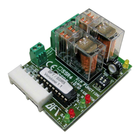
BFT SSR4 User manual

BFT

BFT SSR4 User manual

BFT IGEA LB User manual

BFT

BFT IGEA LB User manual

BFT VISTA SEL SW User manual

BFT

BFT VISTA SEL SW User manual

BFT SUB EL User manual

BFT

BFT SUB EL User manual

BFT BFT-P926192 User manual

BFT

BFT BFT-P926192 User manual

Popular Controllers manuals by other brands

KMB NOVAR-1 S400 Series operating manual

KMB

KMB NOVAR-1 S400 Series operating manual

Hitecsa FLEXIA-K YAP1F6 user manual

Hitecsa

Hitecsa FLEXIA-K YAP1F6 user manual

Sun Microsystems Sun StorageTek 2500 Series Removal and Replacement

Sun Microsystems

Sun Microsystems Sun StorageTek 2500 Series Removal and Replacement

Air Torque AT1001U/PT1000B manual

Air Torque

Air Torque AT1001U/PT1000B manual

Johnson Controls EDA-2040 Installation

Johnson Controls

Johnson Controls EDA-2040 Installation

Eaton xComfort CSAU-01/01-10I Assembly instructions/use and care manual

Eaton

Eaton xComfort CSAU-01/01-10I Assembly instructions/use and care manual

Johnson Controls M9308-A Z Series installation guide

Johnson Controls

Johnson Controls M9308-A Z Series installation guide

Zengge D Series manual

Zengge

Zengge D Series manual

Flomatic FDHC-100 Configuration and operation manual

Flomatic

Flomatic FDHC-100 Configuration and operation manual

LAE electronic AR2-5 Instructions for use

LAE electronic

LAE electronic AR2-5 Instructions for use

LINK-MI LM-R90U user manual

LINK-MI

LINK-MI LM-R90U user manual

AQUATO K-Pilot 8.3 operating instructions

AQUATO

AQUATO K-Pilot 8.3 operating instructions

4qd pro-150 instruction manual

4qd

4qd pro-150 instruction manual

Risco PAN08-1B manual

Risco

Risco PAN08-1B manual

Victron energy CCGX Troubleshooting

Victron energy

Victron energy CCGX Troubleshooting

Mitsubishi Electric MELSEC iQ-R Series Startup User's Manual

Mitsubishi Electric

Mitsubishi Electric MELSEC iQ-R Series Startup User's Manual

Rain ZENIT VISION user manual

Rain

Rain ZENIT VISION user manual

LCS LCS ASC2 owner's manual

LCS

LCS LCS ASC2 owner's manual

manuals.online logo
manuals.online logoBrands
  • About & Mission
  • Contact us
  • Privacy Policy
  • Terms and Conditions

Copyright 2025 Manuals.Online. All Rights Reserved.