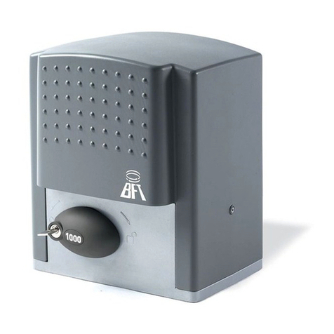
BFT OBERON TRI A2000 INV User manual

INSTALLATION AND USER’S MANUAL
INSTRUCCIONES DE USO Y DE INSTALACION
ACTUATOR FOR RACK SLIDING GATES
ACCIONADOR PARA CANCELAS CORREDERAS DE CREMALLERA
Caution! Read“Warnings”inside carefully! ¡Atención¡ Leer atentamente las“Advertencias”en el interior!
D811957_01 02-04-13
OBERON TRI A2000 INV
8027908 426444
N26683
ORIGINALE

QUICK INSTALLATION -
INSTALACIÓN RÁPIDA
3x0,75mm2
2x0,75mm
2
3x0,75mm
2
2x1.5mm
2
RG58
230V ~3x2.5 mm
2
230V ~3x2.5 mm
2
5x0,75mm
2
A
TUBE ARRANGEMENT,
DISPOSICIÓN DE TUBOS,
B
SECURING THE BASE WITH ANCHORS,
ANCLAJE BÁSICO CON TIRAFONDOS,
Pinion exit side
Lato salita piñón
65mm
Min. 10mm 35mm÷75mm
Top level
Plano superior
115 mm ± 5mm
C
PREPARATION FOR MOTOR MOUNTING, DISPOSICIÓN FIJACIÓN MOTOR,
V1 R1
V3 R3
V2 R2
4mm
10mm
4,3mm
10mm
6,4mm
8mm
V2
R2
R2
V3
R3
V2
C1
C2
C3
C4
V1
R1
10mm
4mm
4,3mm
OK
a) Before commencing installation, make sure you read the warnings.
a) Antes de comenzar con la instalación es necesario leer las adver-
tencias.
b) In addition to the gures, you must follow the instructions given in the relevant section on page 8
b) Además de las guras, es necesario seguir las indicaciones dadas en el apartado correspondiente en pág. 14
2 - OBERON TRI A2000 INV
D811957_01

D
D2 V4
PREPARATION FOR MOTOR MOUNTING, DISPOSICIÓN FIJACIÓN MOTOR,
V4
D2
R5
R4
D1
max 10 mm
R5
R4
D1 13mm
D5
D6
/Not provided
No incluido en el kit/
12mm
10mm 12mm
10mm
12mm
12,5mm
28mm
25mm
OBERON TRI A2000 INV - 3
D811957_01

F
F1
F2
E
V5
FITTING THE RACK / MONTAJE CREMALLERA ADJUSTING THE LIMIT SWITCHES / REGULACIÓN DEL FINAL DE CARRERA
ADJUSTING THE LIMIT SWITCHES / REGULACIÓN DEL FINAL DE CARRERA
LIMIT SWITCH/
FINALES DE CARRERA/ CAM A/LEVA A
CAM B/ LEVA B
OPENING/APERTURA
OPENING REVERSE DIP SWITCH / DIP INVERSIÓN APERTURA
CLOSING / CIERRE
1 2 3 4
24
CLICK
CLICK
Min. 100mm
Min. 150mm
A
B
A
B
163 5mm
+
-
4mm
30mm
V5
DIP = 0 DIP = 1
CAM A
LEVA A Opening / Apertura Closing / Cierre
CAM B
LEVA B Closing / Cierre Opening / Apertura
4 - OBERON TRI A2000 INV
D811957_01

M
NO OK
L
WELDING THE RACK / SOLDADURA CREMALLERA
I
542 324
Ø100mm
z25
M4
305 35,75
20
524
291 233
744,5
110
45
H
Motor / Motor
PG 13,5
V3
PG 9 Accessories/
Accesorios/
V3
10 mm
4 mm
G
BLUE
(neutral)
AZUL
(neutro)
BROWN
(live)
MARRÓN
(fase)
EARTH
TIERRA
(YELLOW/GREEN)
(AMARILLO/VERDE)
ENGLISH ESPAÑOL
OBERON TRI A2000 INV - 5
D811957_01

R/L1 S/L2/N
BROWN
MARRÓN
BLUE / AZUL
EARTH / TIERRA
JP40
OUT NO CC F R S1 S2 P24
FLA FLB FLC CC VI P5 FM
BLUE / AZUL
ORANGE / ANARANJADO
BLACK / NEGRO
VIOLET/VIOLETAGREEN / VERDE
GREY/GRIS
RED / ROJO
YELLOW / AMARILLO
BROWN / MARRÓN
WHITE / BLANCO
JP36
JP35
P0 PA/+ PC/- U/T1 V/T2 W/T3
SHIELD
BROWN / MARRÓN
GREY/GRIS
BLACK / NEGRO
M
N
Y #
50 51 52
20 21L N
60 6162 63 6465 70 71 72737475 76 7778
JP36 JP35
JP38
JP40
26 27 40 4142 43
OUT NO CC F R S1 S2 P24
FLA FLB FLC CC VI P5 FM
R/L1 S/L2/N
P0 PA/+ PC/- U/T1 V/T2 W/T3
MODBUS/
VP8S
DC REACTOR
INVERTER WIRING DIAGRAM - ESQUEMA CABLEADO DEL INVERTER

INSTALLER WARNINGS
Anything that is not explicitly provided for in the installation ma-
nual is not allowed. The operator’s proper operation can only be
guaranteed if the information given is complied with.The Firm shall
not be answerable for damage caused by failure to comply with the
instructions featured herein.
Whilewewillnotaltertheproduct’sessentialfeatures,theFirmreserves
the right, at any time, to make those changes deemed opportune to
improve the product from a technical, design or commercial point of
view, and will not be required to update this publication accordingly.
WARNING! Important safety instructions. Carefully read and comply with
all the warnings and instructions that come with the product as incorrect
installationcan causeinjurytopeopleandanimalsand damagetoproperty.
Thewarningsandinstructionsgiveimportantinformationregardingsafety,
installation,useand maintenance.Keep hold ofinstructions sothat you can
attach them to the technical le and keep them handy for future reference.
GENERAL SAFETY
This product has been designed and built solely for the purpose indicated herein.
Uses other than those indicated herein might cause damage to the product and
create a hazard.
-Theunitsmakingupthemachine anditsinstallationmustmeetthe requirements
of the following European Directives, where applicable: 2004/108/EC, 99/05/EC
andlateramendments. For allcountries outsidethe EEC,it isadvisable tocomply
with the standards mentioned, in addition to any national standards in force, to
achieve a good level of safety.
-The Manufacturer of this product (hereinafter referred to as the“Firm”) disclaims
all responsibility resulting from improper use or any use other than that for
which the product has been designed, as indicated herein, as well as for failure
to apply Good Practice in the construction of entry systems (doors, gates, etc.)
and for deformation that could occur during use.
-Installation must be carried out by qualied personnel (professional installer,
according to EN 12635), in compliance with Good Practice and current code.
-Before installing the product, make all structural changes required to produce
safety gaps and to provide protection from or isolate all crushing, shearing and
dragging hazard areas and danger zones in general in accordance with the
provisions of standards EN 12604 and 12453 or any local installation standards.
Check that the existing structure meets the necessary strength and stability
requirements.
-Before commencing installation, check the product for damage.
-The Firm is not responsible for failure to apply Good Practice in the construction
and maintenance of the doors, gates, etc. to be motorized, or for deformation
that might occur during use.
-Make sure the stated temperature range is compatible with the site in which the
automated system is due to be installed.
-Theoperatorsarenotdesignedtobeused inanyhazardousareasorareassubject
to ooding etc
-Donotinstallthisproduct inanexplosiveatmosphere:thepresenceofammable
fumes or gas constitutes a serious safety hazard.
-Disconnect the electricity supply before performing any work on the system.
Also disconnect buer batteries, if any are connected.
-Before connecting the power supply, make sure the product’s ratings match the
mains ratings and that a suitable residual current circuit breaker and overcurrent
protection device have been installed upline from the electrical system. Have
the automated system’s mains power supply tted with a switch or omnipolar
thermal-magnetic circuit breaker with a contact separation that meets code
requirements.
-Make sure that upline from the mains power supply there is a residual current
circuit breaker that trips at no more than 0.03A as well as any other equipment
required by code.
-Make sure the earth system has been installed correctly: earth all the metal parts
belonging to the entry system (doors, gates, etc.) and all parts of the system
featuring an earth terminal.
-Installation must be carried out using safety devices and controls that meet
standards EN 12978 and EN 12453.
-Impact forces can be reduced by using deformable edges.
-Intheeventimpactforcesexceedthevalueslaid downbytherelevantstandards,
apply electro-sensitive or pressure-sensitive devices.
-Apply all safety devices (photocells, safety edges, etc.) required to keep the
area free of impact, crushing, dragging and shearing hazards. Bear in mind the
standards and directives in force, Good Practice criteria, intended use, the instal-
lation environment, the operating logic of the system and forces generated by
the automated system.
-Always incorporate the appropriate Photo Electric Cells, In-
duction Loops and any other safety devices to protect both equip-
ment and personnel. Extra caution should be employed when using
operator in auto close mode.
-Apply all signs required by current code to identify hazardous areas (residual
risks).
-Once installation is complete, apply a nameplate featuring the door/gate’s data.
-Thisproductcannotbeinstalledon leavesincorporatingdoors(unless themotor
can be activated only when the door is closed).
-If the automated system is installed at a height of less than 2.5 m or is accessible,
the electrical and mechanical parts must be suitably protected.
-Install any xed controls in a position where they will not cause a hazard, away
from moving parts. More specically, hold-to-run controls must be positioned
withindirectsight of the partbeing controlledand, unless they arekeyoperated,
must be installed at a height of at least 1.5 m and in a place where they cannot
be reached by the public.
-Apply at least one warning light (ashing light) in a visible position, and also
attach a Warning sign to the structure.
-Attach a label near the operating device, in a permanent fashion, with informa-
tion on how to operate the automated system’s manual release.
-Make sure that, during operation, mechanical risks are avoided or relevant
protective measures taken and, more specically, that nothing can be banged,
crushed, caught or cut between the part being operated and surrounding parts.
-Once installation is complete, make sure the motor automation settings are
correct and that the safety and release systems are working properly.
-Only use original spare parts for any maintenance or repair work. The Firm dis-
claims all responsibility for the correct operation and safety of the automated
system if parts from other manufacturers are used.
-Do not make any modications to the automated system’s components unless
explicitly authorized by the Firm.
-Instruct the system’s user on what residual risks may be encountered, on the
control systems that have been applied and on how to open the system manu-
ally in an emergency. give the user guide to the end user.
-Dispose of packaging materials (plastic, cardboard, polystyrene, etc.) in accord-
ance with the provisions of the laws in force. Keep nylon bags and polystyrene
out of reach of children.
WIRING
WARNING!Forconnectionto the mainspowersupply,use:a multicorecable with
a cross-sectional area of at least 5x1.5mm2or 4x1.5mm2when dealing with three-
phase power supplies or 3x1.5mm2for single-phase supplies (by way of example,
type H05 VV-F cable can be used with a cross-sectional area of 4x1.5mm2).To con-
nect auxiliaryequipment,use wires with a cross-sectional areaof at least 0.5 mm2.
- Only use pushbuttons with a capacity of 10A-250V or more.
- Allelectricalconnectionsandwiring mustbeperformedwithAS/NZS3000-2007
astheguidelines.(Or its counterpartfor other countries outside of Australia and
New Zealand)
- Wiresmustbesecuredwithadditionalfasteningneartheterminals(forexample,
using cable clamps) in order to keep live parts well separated from safety extra
low voltage parts.
- During installation, the power cable must be stripped to allow the earth wire
to be connected to the relevant terminal, while leaving the live wires as short
as possible. The earth wire must be the last to be pulled taut in the event the
cable’s fastening device comes loose.
WARNING! safety extra low voltage wires must be kept physically separate from
low voltage wires.
Only qualied personnel (professional installer) should be allowed to access
live parts.
CHECKING THE AUTOMATED SYSTEM AND MAINTENANCE
Beforetheautomatedsystemisnallyputintooperation,andduringmaintenance
work, perform the following checks meticulously:
-Make sure all components are fastened securely.
-Check starting and stopping operations in the case of manual control.
-Check the logic for normal or personalized operation.
-For sliding gates only: check that the rack and pinion mesh correctly with 2 mm
of play along the full length of the rack; keep the track the gate slides on clean
and free of debris at all times.
-For sliding gates and doors only: make sure the gate’s running track is straight
and horizontal and that the wheels are strong enough to take the weight of the
gate.
-IMPORTANT ensure there are gate stops firmly installed in the ful-
ly open and closed positions. These stops need to be engineered and in-
stalled such that they will be strong enough to stop the gate should
the limits fail at any time.
-
For cantilever sliding gates only: make sure there is no dipping or swinging
during operation.
-For barriers only: before opening the door, the spring must be decompressed (vertical
boom).
-For swing gates only: make sure the leaves’axis of rotation is perfectly vertical.
-Check that all safety devices (photocells, safety edges, etc.) are working properly
and that the anti-crush safety device is set correctly, making sure that the force
of impact measured at the points provided for by standard EN 12445 is lower
than the value laid down by standard EN 12453.
-Impact forces can be reduced by using deformable edges.
-Make sure that the emergency operation works, where this feature is provided.
-Check opening and closing operations with the control devices applied.
-Check that electrical connections and cabling are intact, making extra sure that
insulating sheaths and cable glands are undamaged.
-While performing maintenance, clean the photocells’optics.
-When the automated system is out of service for any length of time, activate the
emergency release (see“EMERGENCY OPERATION”section) so that the operated
part is made idle, thus allowing the gate to be opened and closed manually.
-
If the power cord is damaged, it must be replaced by the manufacturer or their
technical assistance department or other such qualied person to avoid any risk .
-If “D” type devices are installed (as dened by EN12453), connect in unveried
mode, foresee mandatory maintenance at least every six months
-The maintenance described above must be repeated at least once yearly or at
shorter intervals where site or installation conditions make this necessary.
WARNING!
Remember that the drive is designed to make the gate/door easier to use and
will not solve problems as a result of defective or poorly performed installation
or lack of maintenance
SCRAPPING
Materials must be disposed of in accordance with the regulations in force. There
areno particularhazards or risks involvedin scrapping the automatedsystem. For
the purpose of recycling, it is best to separate dismantled parts into like materials
(electrical parts - copper - aluminium - plastic - etc.).
DISMANTLING
Iftheautomatedsystemisbeingdismantledin ordertobereassembledat another
site, you are required to:
-Cut o the power and disconnect the whole electrical system.
-Remove the actuator from the base it is mounted on.
-Remove all the installation’s components.
-See to the replacement of any components that cannot be removed or happen
to be damaged.
ENGLISH
OBERON TRI A2000 INV - 7
D811957_01

INSTALLATION MANUAL
1) GENERAL INFORMATION
The OBERON TRI A2000 INV operator consists of a strong gearmotor.
The inverter and brake allow the gate to stop quickly, avoiding uncontrolled
sliding of the gate due to the eect of inertia.
The gearmotor is coupled to the gate by means of a rack.
The control unit, inverter, thermal-magnetic circuit breaker and limit switch
assembly are built in.
Theoperating logicprovidesforvarious congurationsso that use oftheautoma-
ted device can be tailored to the user’s needs (e.g.: automatic closing, controlled
closing, photocells active during closing etc.). To edit settings, call in qualied
personnel (installer).
The electronic brake keeps the gate locked closed, meaning there is no need to
use solenoid locks.
A manual release system allows the gate to be opened manually in the event of
a mains power outage or malfunctioning.
We recommend tting a shock absorber prole.
2) TECHNICAL SPECIFICATIONS
GEARMOTOR
Power supply 220-230V 50-60Hz (*)
Power demand 0,75 kW
Thermal overload protection Inverter
Reduction ratio 1/15
Pinion module m=4mm z=25 teeth
Maximum leaf weight 20000N (≈2000kg)
Leaf speed (adjustable) max. AP=39 m/min
Impact reaction stop and reverse
Gearbox lubrication oil
Manual operation mechanical release
Control unit SIRIO CBA 230 INV
Environmental conditions from -10°C to +50°C
Protection rating IP 24
Dimensions Fig.I
Operator weight ~ 60 kg.
Max. travel 20 m
Out speed 125 rpm
Use 60%
3) TUBE ARRANGEMENT Fig.A
Installthe electrical system referring to the standards in force for electrical systems,
IEC 364, harmonization document HD 384 and other national standards.
4) PREPARATION FOR MOTOR MOUNTING FIG. B
Make a hole in the ground to accommodate the concrete pad, with anchors
embedded in the base plate for fastening the gearbox assembly, keeping to the
distances featured in FIG.B.
5 MOUNTING THE GEARMOTOR FIG.C/D
When the casting has hardened, make all the mains and accessory connection
cables go through, letting them protrude from the foundation plate by approxi-
mately 1 metre.
Open the door and unscrew the 6 screws which x the protective cover and
casing (right side) to the base using a suitable key (Fig. C ref. C1).
Then unscrew one screw wich x the shield guard to the protective cover, us-
ing a suitable key (Fig. C ref. C2). Finally remove casing and after the protective
cover (Fig. C ref. C3, C4).
Observe g. D and proceed as follows:
1) Position the actuator over the plate, and insert all the cables or pipes in the
appropriate hole, and the tie rods in the xing slots.
2) Thread a at spacer washer, a spring washer and an M12 (Fig. D ref. D1/R4/
R5) nut on each one of the four base tie rods. Leave the nuts loose for correct
positioning.
3) Adjust the four levelling grub screws (Fig. D ref. D5) to level the actuator so
that it sits approx. 8-10 mm o the foundation base.
4) Running the actuator in the relevant slots, position the motor so that the
drive gear meshes correctly on the rack (Fig.B).Then fasten the four nuts (Fig.
D ref. D6) holding the actuator on the foundation plate.
Note: the rack teeth should mesh with the pinion along their entire width.
6) FITTING THE RACK (FIG.E-L)
7) RACK CENTRING WITH RESPECT TO PINION FIG.M
DANGER - Welding must be performed by a competent person issued
with the necessary personal protective equipment as prescribed by
the safety rules in force.
8) ADJUSTING THE LIMIT SWITCHES (FIG.F)
Loosen the screws and remove the cover (Fig. F).
WARNING! When adjusting the limit switches, keep a safe distance from the
stops.(Fig. F1).
ProceedasindicatedinFig.F2toadjusttheopeningandclosingtravellimitpoints.
9) WIRING AND CONNECTIONS
Connect the mains power to the thermal-magnetic circuit breaker (Fig.G).
Arrange the cabling and t the board protection support. (Fig.H).
10) DO NOT EDIT INVERTER SETTINGS. PROGRAMMING TO BE
CARRIED OUT VIA SIRIO CBA 230 INV CARD ONLY
11) SEE THE CONTROL UNIT’S USER GUIDE FOR INFORMATION
ON SETTING THE MOTOR’S PARAMETERS
12 DIMENSIONS FIG.I
13 MANUAL RELEASE SEE USER GUIDE FIG.2.
Warning: do not JERK the gate open and closed, instead push it GENTLY
to the end of its travel
8 - OBERON TRI A2000 INV
D811957_01

¡ATENCIÓN!Instrucciones de seguridad importantes. Leer y seguir con atención
todas las advertencias y las instrucciones que acompañan el producto, ya que
la instalación incorrecta puede causar daños a personas, animales o cosas. Las
advertenciasylasinstruccionesbrindanimportantesindicacionesconcernientes
a la seguridad, la instalación, el uso y el mantenimiento. Conservar las instruc-
ciones para adjuntarlas a la documentación técnica y para consultas futuras.
SEGURIDAD GENERAL
Este producto ha sido diseñado y fabricado exclusivamente para el uso indicado en
la presente documentación. Otros usos diferentes a lo indicado podrían ocasionar
daños al producto y ser causa de peligro.
-Los elementos de fabricación de la máquina y la instalación deben presentar
conformidad con las siguientes Directivas Europeas, donde se puedan aplicar:
2004/108/CE, 99/05/CE y sus posteriores modicaciones. Para todos los países extra
CEE, además de las normas nacionales vigentes, para lograr un nivel de seguridad
apropiado se deben respetar también las normas antes citadas.
-La Empresa fabricante de este producto (en adelante“empresa”) no se responsabili-
za por todo aquello que pudiera derivar del uso incorrecto o diferente a aquel para
el cual está destinado e indicado en la presente documentación, como tampoco
por el incumplimiento de la Buena Técnica en la fabricación de los cierres (puertas,
cancelas, etc.), así como por las deformaciones que pudieran producirse durante su
uso.
-La instalación debe ser realizada por personal cualicado (instalador profesional, con-
forme a EN12635), en cumplimiento de la Buena Técnica y de las normas vigentes.
-Antes de instalar el producto, realizar todas las modicaciones estructurales de
modo tal que se respeten las distancias de seguridad y para la protección o aisla-
miento de todas las zonas de aplastamiento, corte, arrastre y de peligro en general,
según lo previsto por las normas EN 12604 y 12453 o eventuales normas locales
de instalación. Comprobar que la estructura existente cumpla con los requisitos
necesarios de resistencia y estabilidad.
-Antes de comenzar la instalación, comprobar la integridad del producto.
-La Empresa no es responsable del cumplimiento de la Buena Técnica en la reali-
zación y mantenimiento de los cerramientos por motorizar, como tampoco de las
deformaciones que surgieran durante el uso.
-Comprobar que el intervalo de temperatura declarado sea compatible con el lugar
destinado para instalar la automatización.
- Los operadores no están diseñados para ser utilizados en áreas peligrosas o en
áreas sujetas inundaciones, etc.
-No instalar este producto en atmósfera explosiva. la presencia de gases o humos
inamables constituye un grave peligro para la seguridad.
-Antes de realizar cualquier intervención en la instalación, interrumpir la alimenta-
ción eléctrica. Desconectar también eventuales baterías compensadoras si estuvie-
ran presentes.
-Antes de conectar la alimentación eléctrica, asegurarse de que los datos de placa
correspondan a los de la red de distribución eléctrica y que en el origen de la ins-
talación eléctrica haya un interruptor diferencial y una protección de sobrecarga
adecuados. En la red de alimentación de la automatización, se debe prever un in-
terruptor o un magnetotérmico omnipolar, con una distancia de apertura de los
contactos conforme a lo previsto por las normas vigentes.
-
Comprobar que en el origen de la red de alimentación, haya un interruptor diferencial
con umbral no superior a 0.03A y conforme a lo previsto por las normas vigentes.
-Comprobar que la instalación de puesta a tierra esté realizada correctamente: co-
nectar a tierra todas las piezas metálicas del cierre (puertas, cancelas, etc.) y todos
los componentes de la instalación con borne de tierra.
-La instalación se debe realizar utilizando dispositivos de seguridad y de mandos
conformes a la EN 12978 y EN12453.
-Las fuerzas de impacto pueden ser reducidas utilizando cantos deformables.
-Si las fuerzas de impacto superan los valores previstos por las normas, aplicar dispo-
sitivos electrosensibles o sensibles a la presión.
-Aplicar todos los dispositivos de seguridad (fotocélulas, cantos sensibles, etc.) ne-
cesarios para proteger el área de peligros de impacto, aplastamiento, arrastre, cor-
te. Tener en cuenta las normativas y las directivas vigentes, los criterios de la Buena
Técnica, el uso, el entorno de instalación, la lógica de funcionamiento del sistema y
las fuerzas desarrolladas por la automatización.
-Siempre incorpore las celdas fotoeléctricas apropiadas, los lazos de inducción y
otros dispositivos de seguridad para garantizar la protección del equipo y del per-
sonal. Se debe prestar una precaución extra cuando se usa el operador in modo
cierre automático.
-Aplicar las señales previstas por las normativas vigentes para identicar las zonas
peligrosas (los riesgos residuales).
-Una vez completada la instalación, colocar una placa de identicación de la puerta/
cancela.
-Este producto no se puede instalar en hojas que incorporan puertas (salvo que el
motor se active sólo cuando la puerta está cerrada)
-Si la automatización es instalada a una altura inferior a 2,5 m o está al alcance, es
necesario garantizar un grado de protección adecuado de las piezas eléctricas y
mecánicas.
-Instalar cualquier mando jo en una posición que no cause peligros y alejado de
las piezas móviles. En particular los mandos con hombre presente estén colocados
a la vista directa de la parte guiada y, salvo que no sean con llave, se deben instalar
a una altura mínima de 1,5 m y de manera tal de que no sean accesibles para el
público.
-Aplicar al menos un dispositivo de señalización luminosa (parpadeante) en posi-
ción vertical, además jar a la estructura un cartel de Atención.
-
Fijar de manera permanente una etiqueta correspondiente al funcionamiento del des-
bloqueo manual de la automatización y colocarla cerca del órgano de maniobra.
-Asegurarse de que durante la maniobra se eviten y se proteja de los riesgos me-
cánicos y en particular el impacto, el aplastamiento, arrastre, corte entre la parte
guiada y las partes jas alrededor.
-Una vez realizada la instalación, asegurarse de que el ajuste de la automatización
del motor esté congurado de manera correcta y que los sistemas de protección y
de desbloqueo funcionen correctamente.
-Usar exclusivamente piezas originales para todas las operaciones de mantenimien-
to y reparación. La Empresa no se responsabiliza de la seguridad y el buen fun-
cionamiento de la automatización, en caso que se utilicen componentes de otros
fabricantes.
-No realizar ninguna modicación a los componentes de la automatización si no se
cuenta con autorización expresa por parte de la Empresa.
-Instruir al usuario de la instalación sobre los eventuales riesgos residuales, los siste-
mas de mando aplicados y la ejecución de la maniobra de apertura manual en caso
de emergencia: entregar el manual de uso al usuario nal.
-Eliminar los materiales de embalaje (plástico, cartón, poliestireno, etc.) según lo
previsto por las normas vigentes. No dejar sobres de nylon y poliestireno al alcance
de los niños.
Todo aquello que no expresamente previsto en el manual de instalación,
no está permitido. El buen funcionamiento del operador es garantizado
sólo si se respetan los datos indicados. La Empresa no se responsabiliza
por los daños causados por el incumplimiento de las indicaciones dadas
en el presente manual.
Dejandoinalteradaslascaracterísticasesencialesdelproducto,laEmpresa
se reserva el derecho de realizar, en cualquier momento, modicaciones
que considere convenientes para mejorar la técnica, la fabricación y la
comercializacióndelproducto,sincomprometerseaactualizarlapresente
publicación.
ADVERTENCIAS PARA LA INSTALACIÓN
CONEXIONES
¡ATENCIÓN! Para la conexión a la red utilizar: cable multipolar de sección mínima de
5x1,5mm2ó 4x1,5mm2para alimentaciones trifásicas o bien 3x1,5mm2para alimen-
taciones monofásicas (a modo de ejemplo, el cable puede ser del tipo H05 VV-F con
sección de 4x1.5mm2). Para la conexión de los dispositivos auxiliares utilizar conduc-
tores con sección mínima de 0,5 mm2.
- Utilizar exclusivamente pulsadores con capacidad no inferior a 10A-250V.
- Todas las conexiones eléctricas y los cableados se deben realizar siguiendo las pau-
tas de AS/NZS 3000-2007. (O sus equivalencias en otros países que no sean Austra-
lia y Nueva Zelanda)
- Los conductores deben estar unidos por una jación suplementaria cerca de los
bornes (por ejemplo mediante abrazaderas) para mantener bien separadas las par-
tes bajo tensión de las partes con muy baja tensión de seguridad.
- Durante la instalación se debe quitar la funda del cable de alimentación para per-
mitir la conexión del conductor de tierra al borne especíco, dejando los conducto-
res activos lo más cortos posible. El conductor de tierra debe ser el último a tensar-
se en caso de aojamiento del dispositivo de jación del cable.
¡ATENCIÓN! los conductores a muy baja tensión de seguridad se deben mantener
físicamente separados de los circuitos a baja tensión.
La accesibilidad a las partes bajo tensión debe ser posible exclusivamente para el
personal cualicado (instalador profesional).
CONTROL DE LA AUTOMATIZACIÓN Y MANTENIMIENTO
Antes de que la automatización quede denitivamente operativa, y durante las in-
tervenciones de mantenimiento, controlar estrictamente lo siguiente:
-Comprobar que todos los componentes estén jados rmemente.
-Controlar la operación de arranque y parada en el caso de mando manual.
-Controlar la lógica de funcionamiento normal o personalizada.
-Sólo para cancelas correderas: comprobar el correcto engranaje de la cremallera -
piñón con un juego de 2 mm a lo largo de toda la cremallera; mantener el carril de
desplazamiento siempre limpio y libre de desechos.
-Sólo para cancelas y puertas correderas: comprobar que la vía de desplazamiento
de la cancela sea lineal, horizontal y las ruedas sean aptas para soportar el peso de
la cancela.
-IMPORTANTE: asegúrese de que haya retenedores de compuerta bien instalados en
las posiciones de compuerta completamente abierta y cerrada. Estos retenedores
se deben proyectar e instalar en manera tal de ser lo sucientemente fuertes para
detener la puerta si los límites fallan en algún momento.- Sólo para can-
celas correderas suspendidas (Cantilever): comprobar que no se produzca ninguna
bajada u oscilación durante la maniobra.
-Sólo para cancelas batientes: comprobar que el eje de rotación de las hojas esté en
posición perfectamente vertical.
-Sólo para barreras: antes de abrir la portezuela el muelle debe estar descargado
(mástil vertical).
-Controlar el correcto funcionamiento de todos los dispositivos de seguridad (foto-
células, cantos sensibles, etc.) y el correcto ajuste de los dispositivos de seguridad
antiaplastamiento, comprobando que el valor de la fuerza de impacto, medido en
los puntos previstos por la norma EN 12445, sea inferior a lo indicado en al norma
EN 12453.
-Las fuerzas de impacto pueden ser reducidas utilizando cantos deformables.
-
Controlar el buen funcionamiento de la maniobra de emergencia donde esté presente.
-
Controlar la operación de apertura y cierre con los dispositivos de mando aplicados.
-Comprobar la integridad de las conexiones eléctricas y de los cableados, en parti-
cular el estado de las cubiertas aislantes y de los sujetacables.
-Durante el mantenimiento limpiar las ópticas de las fotocélulas.
-
Durante el periodo en que la automatización está fuera de servicio, activar el desblo-
queo de emergencia (véase apartado “MANIOBRA DE EMERGENCIA”), de manera tal de
dejar libre la parte guiada y permitir la apertura y el cierre manual de la cancela.
-Si el cable de alimentación está dañado, el mismo debe ser sustituido por el fa-
bricante o por el servicio de asistencia técnica de éste o por una persona con una
capacitación similar, de manera tal de prevenir cualquier riesgo.
-Si se instalan dispositivos de tipo “D” (tal como los dene la EN12453), conectados
en modo no comprobado, establecer un mantenimiento obligatorio con frecuen-
cia al menos semestral.
- El mantenimiento, como se ha descrito anteriormente, se debe repetir por lo
menos anualmente o con intervalos menores si las características del lugar o
de la instalación lo requirieran.
¡ATENCIÓN!
Recordar que la motorización sirve para facilitar el uso de la cancela/puerta pero
no resuelve problema de defectos o carencias de instalación o de falta de mante-
nimiento.
DESGUACE
La eliminación de los materiales debe hacerse respetando las normas vigentes. En
el caso de desguace de la automatización no existen peligros o riesgos particulares
causados por dicha automatización. En caso de recuperación de los materiales, se
recomienda que los mismos sean separados por tipo (partes eléctricas - cobre - alu-
minio - plástico - etc.).
DESMANTELAMIENTO
Si la automatización es desmontada para luego ser montada nuevamente en otro
sitio hay que:
Interrumpir la alimentación y desconectar toda la instalación eléctrica.
-Quitar el accionador de la base de jación.
-Desmontar todos los componentes de la instalación.
-
Si algunos componentes no pudieran ser quitados o estuvieran dañados, sustituirlos.
ESPAÑOL
OBERON TRI A2000 INV - 9
D811957_01

MANUAL DE INSTALACIÓN
1) DATOS GENERALES
EloperadorOBERONTRIA2000INVestáconstituidoporunmotorreductorrobusto.
Elinvertiryelfrenopermitenparadasrápidasdelahoja,evitandodesplazamientos
por inercia incontrolados de dicha hoja.
El motorreductor se acopla a la cancela mediante una cremallera.
La centralita de mando, el inverter, el magnetotérmico y el grupo nal de carrera
están incorporados.
La lógica de funcionamiento permite diferentes conguraciones para adecuar
mejor el uso de la automatización al equipo (ej.: cierre automático, cierre acciona-
do, fotocélulas activas en fase de cierre, etc.). Para modicar las conguraciones
contactar con personal cualicado (instalador).
El electrofreno mantiene la hoja bloqueada en fase de cierre, haciendo superuo
el uso de cerraduras eléctricas.
Un sistema de desbloqueo manual permite abrir manualmente la hoja en caso
de que falte alimentación de red o de servicio.
Se recomienda montar un perl de canto.
2) DATOS TÉCNICOS
MOTORREDUCTOR
Alimentación 220-230V 50-60Hz (*)
Potencia absorbida 0,75 kW
Protección térmica Inverter
Relación de reducción 1/15
Módulo piñón m=4mm z=25 dientes
Peso máximo hoja 20000N (≈2000kg)
Velocidad hoja (regulable) máx. AP=39 m/min
Reacción al golpe parada e inversión
Lubricación reductor aceite
Accionamiento manual desbloqueo mecánico
Unidad de control SIRIO CBA 230 INV
Condiciones ambientales de -10°C a +50°C
Grado de protección IP 24
Dimensiones Fig. I
Peso operador ~ 60 kg.
Carrera máx. 20 m
Velocidad salida 125 rpm.
Uso 60%
3) PREDISPOSIÇÃO DOS TUBOS FIG.A
Predispor a instalação eléctrica tomando como referência as normas vigentes para as
instalações eléctricas, IEC364, harmonização HD384 e outras normas nacionais.
4) DISPOSICIÓN FIJACIÓN MOTOR FIG. B
Disponer una excavación donde realizar la base de cemento con los tirafondos
de la placa de apoyo para jar el grupo reductor respetando las cotas indicadas
en la FIG.B.
5 MONTAJE MOTORREDUCTOR FIG.C/D
Una vez que la colada se haya endurecido, hay que pasar todos los cables de
conexión de los accesorios y de la red de alimentación, dejando que sobresalgan
aproximadamente 1 metro de la losa de cimentación.
Abrir la portezuela, desenroscar los 6 tornillos que jan la tapa y el cárter IP
(lado derecho) a la base, usando una llave adecuada (Fig. C ref. Fig.C1)
Luego desenroscar el tornillo que ja la pantalla a la tapa usando siempre una
llave adecuada (Fig. C ref. C2) con el n de quitar el cárter IP y la tapa (Fig. C ref.
C3-C4).
Observando la g. D, hay que realizar lo siguiente:
1) Colocar el servomotor encima de la losa, insertando todos los cables o
conductos previstos en el agujero especíco y los tirantes en las ranuras de
jación.
2) Insertar una arandela plana, una arandela Grower y una tuerca M12 en cada
uno de los cuatro tirantes de la base D1/R4/R5. Dejar las tuercas ojas para
permitir la colocación correcta.
3) Regular los cuatro pernos de nivelación (Fig. D ref. D5) de manera tal de
nivelar el accionador elevado aproximadamente 8-10mm respecto a la base
de cimentación.
4) Haciendo desplazar el accionador en las ranuras especícas, posicionar el
motor de manera que la corona motor engrane correctamente en la cre-
mallera (Fig.B).Luego jar las cuatro tuercas (Fig. D ref. D6) que bloquean el
accionador en la plaza de cimentación.
Nota: los dientes de la cremallera tendrán que engranar en el piñón por toda
su anchura.
6) MONTAJE CREMALLERA (FIG.E-L)
7) CENTRADO CREMALLERA RESPECTO AL PIÑÓN FIG.M
PELIGRO – La operación de soldadura debe ser realizada por una
persona capaz y equipada con todos los dispositivos de protección
individuales previstos por las normas de seguridad vigentes.
8) REGULACIÓN DE LOS FINALES DE CARRERA (FIG.F)
Aojar los tornillos y quitar la tapa (Fig. F).
¡ATENCIÓN! En la regulación de los nales de carrera, mantener un espacio de
seguridad en los topes. (Fig. F1).
Proceder como se indica en la Fig. F2 para regular los puntos de los nales de
carrera de apertura y cierre.
9) CABLEADO Y CONEXIONES
Conectar la alimentación de red en el interruptor magnetotérmico (Fig.G).
Disponer el paso de los cableados y montar el soporte protección tarjeta. (Fig.H).
10 NO MODIFICAR LAS CONFIGURACIONES DEL INVERTER: PARA
LAPROGRAMACIÓN,INTERVENIREXCLUSIVAMENTEENLATARJETA
SIRIO CBA 230 INV
11 PARA CONFIGURAR LOS PARÁMETROS DEL MOTOR,
CONSULTAR EL MANUAL DE LA CENTRAL
12) DIMENSIONES FIG.I
13 DESBLOQUEO MANUAL VÉASE MANUAL DE USO FIG.2.
Atención: no empujar VIOLENTAMENTE la hoja de la cancela, sino ACOM-
PAÑARLA en toda su carrera.
10 - OBERON TRI A2000 INV
D811957_01

Fig.1
USER’S MANUAL: MANUAL OPERATION - MANUAL DE USO: ACCIONAMIENTO MANUAL
C
D
A
OPEN
B
E
CLOSE
USER WARNINGS (GB)
WARNING! Important safety instructions. Carefully read and comply with
the Warnings and Instructions that come with the product as improper use
can cause injury to people and animals and damage to property. Keep the
instructions for future reference and hand them on to any new users.
This product is meant to be used only for the purpose for which it was expli-
citly installed. Any other use constitutes improper use and, consequently,
is hazardous. The manufacturer cannot be held liable for any damage as a
result of improper, incorrect or unreasonable use.
GENERAL SAFETY
Thank you for choosing this product. The Firm is condent that its performance
will meet your operating needs.
This product meets recognized technical standards and complies with safety provi-
sions when installed correctly by qualied, expert personnel (professional installer).
If installed and used correctly, the automated system will meet operating safety
standards. Nonetheless, it is advisable to observe certain rules of behaviour so
that accidental problems can be avoided:
-Keep adults, children and property out of range of the automated system,
especially while it is moving.
-Do not allow children to play or stand within range of the automated system.
-This automated system is not meant for use by children or by people with impai-
red mental, physical or sensory capacities, or people who do not have suitable
knowledge, unless a person who is responsible for their safety provides them
with necessary supervision or instructions on how to use the device.
-Children must be supervised to ensure they do not play with the device. Do not
allow children to play with the xed controls. Keep remote controls out of reach
of children.
-Do not work near hinges or moving mechanical parts.
-Donothinder theleaf’smovementanddonotattempttoopenthedoormanually
unless the actuator has been released with the relevant release knob.
-Keep out of range of the motorized door or gate while they are moving.
-Keep remote controls or other control devices out of reach of children in order
to avoid the automated system being operated inadvertently.
-Keep loose clothing and hands clear of the gate whilst in operationorpotentially
able to be operated.
-The manual release’s activation could result in uncontrolled door movements if
there are mechanical faults or loss of balance.
-When using roller shutter openers: keep an eye on the roller shutter while it is
moving and keep people away until it has closed completely. Exercise care when
activating the release, if such a device is tted, as an open shutter could drop
quickly in the event of wear or breakage.
- The breakage or wear of any mechanical parts of the door (operated part), such
as cables, springs, supports, hinges, guides…, may generate a hazard. Have the
system checked by qualied, expert personnel (professional installer) at regular
intervals according to the instructions issued by the installer or manufacturer
of the door.
-When cleaning the outside, always cut o mains power.
-Keep the photocells’optics and illuminating indicator devices clean. Check that
no branches or shrubs interfere with the safety devices.
-Do not use the automated system if it is in need of repair. In the event the auto-
mated system breaks down or malfunctions, cut o mains power to the system;
do not attempt to repair or perform any other work to rectify the fault yourself
and instead call in qualied, expert personnel (professional installer) to perform
the necessary repairs or maintenance. To allow access, activate the emergency
release (where tted).
-If any part of the automated system requires direct work of any kind that is
not contemplated herein, employ the services of qualied, expert personnel
(professional installer).
-Atleast onceayear,have theautomated system,and especially all safetydevices,
checked by qualied, expert personnel (professional installer) to make sure that
it is undamaged and working properly.
-A record must be made of any installation, maintenance and repair work and
the relevant documentation kept and made available to the user on request.
- Failure to comply with the above may result in hazardous situations.
Anything that is not explicitly provided for in the user guide is not allowed.
The operator’s proper operation can only be guaranteed if the instructions
givenhereinarecompliedwith.TheFirmshallnotbeanswerablefordamage
caused by failure to comply with the instructions featured herein.
Whilewe will not alter the product’sessential features,the Firmreservesthe
right, at any time, to make those changes deemed opportune to improve
the product from a technical, design or commercial point of view, and will
not be required to update this publication accordingly.
OBERON TRI A2000 INV - 11
D811957_01

ADVERTENCIAS PARA EL USUARIO (E)
¡ATENCIÓN! Instrucciones de seguridad importantes. Leer y seguir con
atención las Advertencias y las Instrucciones que acompañan el producto,
yaque eluso inapropiadopuede causar daños a personas, animales o cosas.
Guardarlasinstruccionesparafuturasconsultasytransmitirlasaeventuales
reemplazantes en el uso de la instalación.
Este producto se deberá utilizar únicamente para el uso para el cual ha sido
expresamente instalado. Cualquier otro uso se considerará inadecuado y
por lo tanto peligroso El fabricante no se responsabiliza por posibles daños
causados debido a usos inapropiados, erróneos e irrazonables.
SEGURIDAD GENERAL
Leagradecemosporhaberelegidoesteproducto,enlaEmpresaestamosseguros
que obtendrán las prestaciones necesarias para su uso.
Este producto responde a las normas reconocidas de la técnica y de las disposi-
ciones inherentes a la seguridad siempre que haya sido correctamente instalado
por personal cualicado y experto (instalador profesional).
La automatización, si se instala y utiliza de manera correcta, cumple con los es-
tándares de seguridad para el uso. Sin embargo es conveniente respetar algunas
reglas de comportamiento para evitar inconvenientes accidentales:
-Manteneraniños,personasy cosasfueradelradiode accióndelaautomatización,
especialmente durante su movimiento.
-No permitir que los niños jueguen o permanezcan en el radio de acción de la
automatización.
-Estaautomatizaciónnoestádestinadaparaserutilizadaporniñosopor personas
con capacidades mentales, físicas y sensoriales reducidas, o personas que no
cuenten con conocimientos adecuados, salvo que sean supervisadas o hayan
recibido instrucciones de uso del equipo por parte de una persona responsable
de su seguridad.
-Los niños deben ser vigilados para cerciorarse que no jueguen con el equipo.
No permitir que los niños jueguen con los controles jos. Mantener los mandos
a distancia alejados de los niños.
-Evitar operar cerca de las bisagras o de los órganos mecánicos en movimiento.
-No obstaculizar el movimiento de la hoja y no intentar abrir manualmente la
puerta si no se ha desbloqueado el accionador con el botón de desbloqueo
especíco.
-No ingresar al radio de acción de la puerta o cancela motorizadas durante el
movimiento de las mismas.
-No dejar radiomandos u otros dispositivos de mando al alcance de niños, para
evitar accionamientos involuntarios.
-Use vestuario no adherente y mantenga las manos alejadas de la compuerta
mientras está funcionando o pueda ponerse a funcionar.
-La activación del desbloqueo manual podría causar movimientos incontrolados
de la puerta en caso de averías mecánicas o condiciones de desequilibrio.
-En caso de automatizaciones para persianas enrollables: vigilar la persiana en
movimiento y mantener alejadas a las personas hasta que esté completamente
cerrada.Tenerprecaucióncuandoseaccionaeldesbloqueo,siestuvierapresente,
puesto que una persiana enrollable abierta podría caer rápidamente en caso de
desgaste o roturas.
-La rotura o el desgaste de órganos mecánicos de la puerta (parte guiada), como
porejemplocables,muelles,soportes,goznes,guías,etc.podríagenerarpeligros.
Hacercontrolarperiódicamentelainstalaciónpor personal cualicado y experto
(instalador profesional), según lo indicado por el instalador o por el fabricante
de la puerta.
-
Para cualquier operación de limpieza exterior, interrumpir la alimentación de red.
-Mantener limpias las ópticas de las fotocélulas y los dispositivos de señalización
luminosa. Controlar que ramas y arbustos no obstaculicen los dispositivos de
seguridad.
-No utilizar la automatización si necesita intervenciones de reparación. En caso
de avería o de defecto de funcionamiento de la automatización, interrumpir la
alimentación de red en la automatización, abstenerse de cualquier intento de
reparación o intervención directa y recurrir sólo a personal cualicado y experto
(instalador profesional) para la necesaria reparación y mantenimiento. Para
permitir el acceso, activar el desbloqueo de emergencia (si estuviera presente).
Bft Spa
Via Lago di Vico, 44
36015 Schio (VI)
T +39 0445 69 65 11
F +39 0445 69 65 22
www.bft.it
SPAIN
BFT GROUP ITALIBERICA DE
AUTOMATISMOS S.L.
08401 Granollers - (Barcelona)
www.bftautomatismos.com
FRANCE
AUTOMATISMES BFT FRANCE
69800 Saint Priest
www.bft-france.com
GERMANY
BFT TORANTRIEBSSYSTEME Gmb H
90522 Oberasbach
www.bft-torantriebe.de
UNITED KINGDOM
BFT AUTOMATION UK LTD
Stockport, Cheshire, SK7 5DA
www.bft.co.uk
IRELAND
BFT AUTOMATION LTD
Dublin 12
BENELUX
BFT BENELUX SA
1400 Nivelles
www.bftbenelux.be
POLAND
BFT POLSKA SP. Z O.O.
05-091 ZąBKI
www.bft.pl
CROATIA
BFT ADRIA D.O.O.
51218 Drazice (Rijeka)
www.bft.hr
PORTUGAL
BFT SA-COMERCIO DE
AUTOMATISMOS E MATERIAL DE
SEGURANCIA
3020-305 Coimbra
www.bftportugal.com
CZECH REPUBLIC
BFT CZ S.R.O.
Praha
www.bft.it
TURKEY
BFT OTOMATIK KAPI SISTEMELERI
SANAY VE
Istanbul
www.bftotomasyon.com.tr
RUSSIA
BFT RUSSIA
111020 Moscow
www.bftrus.ru
AUSTRALIA
BFT AUTOMATION AUSTRALIA
PTY LTD
Wetherill Park (Sydney)
www.bftaustralia.com.au
U.S.A.
BFT USA
Boca Raton
www.bft-usa.com
CHINA
BFT CHINA
Shanghai 200072
www.bft-china.cn
UAE
BFT Middle East FZCO
Dubai
-Para cualquier intervención directa en la automatización o en la instalación
no prevista por el presente manual, recurrir a personal cualicado y experto
(instalador profesional).
-Almenosunavezal añohacercontrolarlaintegridadyelcorrectofuncionamiento
de la automatización por personal cualicado y experto (instalador profesional),
en particular de todos los dispositivos de seguridad.
-
Lasintervencionesdeinstalación, mantenimientoyreparacióndebenserregistradas
y la documentación correspondiente se debe mantener a disposición del usuario.
-
El incumplimiento de lo antes indicado puede provocar situaciones de peligro.
Todo aquello que no expresamente previsto en el manual de uso, no está
permitido. El buen funcionamiento del operador es garantizado sólo si se
respetan las prescripciones indicadas en el presente manual. La Empresa
no se responsabiliza por los daños causados por el incumplimiento de las
indicaciones dadas en el presente manual.
Dejando inalteradas las características esenciales del producto, la Empresa
se reserva el derecho de realizar, en cualquier momento, modicaciones que
considere convenientes para mejorar la técnica, la fabricación y la comerciali-
zación del producto, sin comprometerse a actualizar la presente publicación.
12 - OBERON TRI A2000 INV
D811957_01
Other manuals for OBERON TRI A2000 INV
2
Table of contents
Languages:
Other BFT Controllers manuals

BFT
BFT caro User manual

BFT
BFT URANO BT User manual

BFT
BFT SP 3500 User manual

BFT
BFT deimos ultra bt a 400 User manual

BFT
BFT ARES User manual

BFT
BFT IGEA LB User manual

BFT
BFT Magistro ROLL User manual

BFT
BFT VISTA SEL SW User manual

BFT
BFT DEIMOS BT A 600 User manual

BFT
BFT DEIMOS BT + QSC D MA User manual

BFT
BFT ALCOR N User manual

BFT
BFT ARES ULTRA BT A 1000 User manual

BFT
BFT ICARO User manual

BFT
BFT ARES Series User manual

BFT
BFT MOOVI 30S RMM User manual

BFT
BFT SP 3500 User manual

BFT
BFT ICARO SMART AC A2000 User manual

BFT
BFT DEIMOS BT A 600 User manual

BFT
BFT IANUS BT 300 KIT User manual

BFT
BFT ARES VELOCE SMART BT A500 User manual