BIG RBX5 User manual

Operation manual
Please be sure to read this manual before using the product
RBX5・RBX5C
RBX7・RBX7C
●INDEX●
SAFETY NOTES
INTRODUCTION
SPECIFICATIONS
UTILIZATION PROCEDURES
1. How to install / remove a cutting tool
2. Initial rotation of the air turbine
3. Spindle speed adjustment
4. Concerning the use of coolants
5. Air nozzles adjustment
6. Pull-stud bolts installation
INSTALLATION
1. Installation of the side through type
2. Installation of the center through type
3. Installation of the manual type
4. Concerning the air supply
OTHER
P 1
P 2
P 3
P 3
P 6
P 6
P 7
P 8
P 8
P 9
P15
P16
P17
P19
Thank you for your purchase of AIR TURBINE SPINDLE.
Please be sure to read this manual before using the product and also keep it in a
location where all the operators may consult it in case of necessity.
Danger
Since the Air Turbine Spindle rotates at very high speed, if the cutting tool breaks during the
process its fragments, scattering, will cause an extremely dangerous situation. During the
process, utilize a safety cover, etc. in case that fragments scatter out and please also take enough
safety measures for protect yourself. In addition, please always wear protective eyeglasses.
Do not rotate the machine spindle when the Air Turbine Spindle is installed on the machine.
(In case of utilizing the manual type, the machine spindle, by turning, may twist the air tube and
cause severe accidents.)
A low speed rotation for few seconds to orientate the side through type is not a problem.
Caution
Do not use it on machines that have previously used coolants, oil mists, etc.
(Foreign bodies invading the holder may reduce its lifespan or cause breakages.)
In case of using BBT, BCV and BDV shanks, please use pull-stud bolts provided with holes
(sold apart)
.
Caution
Please reduce the ATC speed.
(The impact with the ATC may damage the cutting tool in case of using tools with small diameter.)
Warning
Do not touch the cutting tool or the chuck part while the spindle is rotating.
Do not touch the holder rotating part immediately after have stopped the air supply.
(The holder rotating part will rotate by inertia even after have stopped the air supply. Please check
that the rotating part is not moving in case of touching it.)
Please also respect the below notes in case of using the center through type (RBX5C, RBX7C).
SAFETY NOTES
The following safety notes are arranged in order to use correctly our product and to protect the operator
and other people from possible injuries and damages. In order to distinguish the severity of the injury or
damage, the safety notes are divided in three categories “Caution”, “Warning” and “Danger”. Please be
sure to respect the safety notes since any of them contain important safety matters.
This note indicates that the wrong handling of the product may injury people or
cause material damages.
This note indicates a dangerous situation that if not avoided may cause death or
severe injuries.
This note indicates that the wrong handling of the product may cause death or
severe injuries.
Caution
Warning
Danger
:
:
:
1

2
INTRODUCTION
Caution
About the specifications
About the process, the cutting tool installation, the air adjustments, etc
About the installation on the machine tool and the air supply
About the storage, maintenance
How to install / remove a cutting tool P3
-
P5
1
Maintenance P19
2
Long period storage and re-use P19
1
Pull-stud bolts installation P8
6
Air nozzles adjustment P8
5
Concerning the use of coolants P7
4
Spindle speed adjustment P6
3
Initial rotation of the air turbine P6
2
Specifications P3
1
Concerning the air supply P17
4
In order to be able to use the Air Turbine, it is necessary to install the
machine tool, air supply, etc. Please consult the below
and conduct the installation correctly.
SPECIFICATIONS
INSTALLATION
UTILIZATION PROCEDURES
OTHER
INSTALLATION
321 Installation of
the side
through type
Installation of
the center
through type
Installation
of the manual
type
P9
-
P14 P15 P16

Caution
Before installing a cutting tool, always use, on the internal diameter of the chuck, the internal and
external surfaces of the collet and on the shank of the cutting tool, kerosene or other degreasing
agents and wipe the dirty parts with a cloth.
Warning
The Air Turbine Spindle rotates at very high speed. In case of using cutting tools with a big
unbalance or tools with small diameter and long overhang, due to the centrifugal force, the
cutting tool may break creating an extremely dangerous situation. Use a cutting tool with high
rigidity and make it short as much as possible.
SPECIFICATIONS
UTILIZATION PROCEDURES
Clamping range (mm)
Tool diameter (mm)
Minimum spindle speed (min-1)
Maximum spindle speed (min-1)
Collet
ø0.45
-
4.05
ø1.5 or smaller
About 40,000 (0.3MPa)
About 50,000 (0.6MPa)
NBC4S-dAA (Option)
ø0.45
-
4.05
ø1.5 or smaller
About 60,000 (0.3MPa)
About 80,000 (0.6MPa)
NBC4S-dAA (Option)
Type RBX5 / RBX5C RBX7 / RBX7C
BIG-PLUS is a standard product of BIG Daishowa Seiki. Use machine tools with the
BIG-PLUS trademark to obtain a correct double face contact. BIG-PLUS holders are
also compatible with spindles of standard machines. In this case, check that there
are not projecting objects in the machine spindle’s surface and in the holder’s surface.
How to install / remove a cutting tool
1
Specifications
1
About BIG-PLUS (BBT, BDV, and BCV)
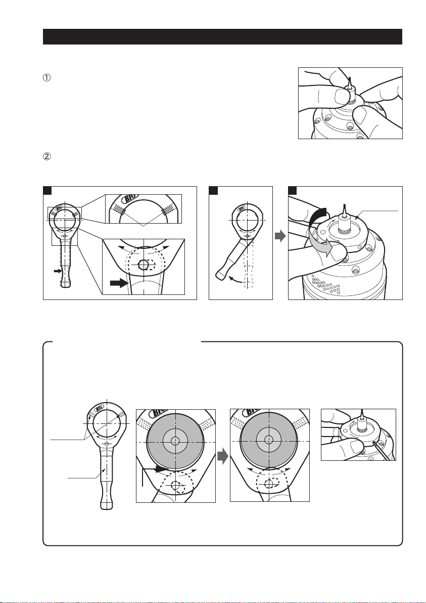
Use the X-Wrench and the Mega Wrench for install/remove the cutting tool. Please consult P4 “How
to use the X-Wrench” regarding how to use the X-Wrench.
Always install the collet in the chuck body
after have inserted it into the nut.
Caution
Insert the collet from the rear part of the nut
and push it until the ribbed part of the collet is
set with a “click”.
It is possible to remove the collet from the nut
by pulling the collet straight along the spindle.
[Collet installation procedures]
[Collet removal procedures]
3
UTILIZATION PROCEDURES
Insert the cutting tool in the collet – nut and tight it lightly with
your hands. Reduce the overhang of the cutting tool as much
as possible. (It greatly influences the T.I.R. and Rigidity.)
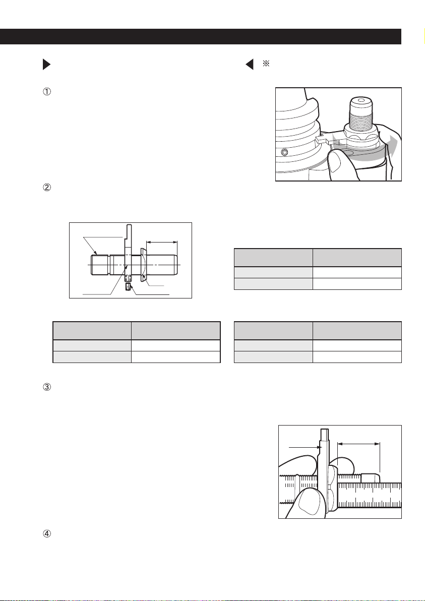
Let project a little bit both side-lock screws of the X-Wrench, shift the handle on the “LOCK” side
and move the handle to the left as shown in the picture FIG 2. Then insert the wrench on the
flange part of the spindle and lock the spindle by moving the handle.
OPEN
LOCK
X
W
2
7
C
O
L
K
E
O
P
N
C
O
L
K
E
O
P
N
Let project a little bit both side-lock screws and
shift the handle on the “LOCK” side.
Shift the handle as
shown in the picture.
Insert the wrench on the flange part of the
spindle and move it on the "LOCK"side.
X
W
2
7
C
O
L
K
E
O
P
N
1 2 3
X-Wrench
(XW27)
[How to install a cutting tool]
The X-Wrench is a wrench that secures the spindle of the Air Turbine when tightening the
collet. It clamps the spindle thanks to the eccentric cam structure of the handle.
Please adjust the 2 side-lock screws if it is not possible to lock.
Please adjust the
side-lock screws on the
wrench if it is not
possible to lock.
OPEN
LOCK
How to use X-Wrench (XW27)
X
W
2
7
C
O
L
K
E
O
P
N
Side-lock
screws
Side-lock screws
Handle
When the wrench is
inserted in the spindle When the nut is tighten
X
W
2
7
C
O
L
K
E
O
P
N
Gap
X
W
2
7
C
O
L
K
E
O
P
N
X
W
2
7
The spindle’s flange is
secured thanks to the
side-lock screws and
to the handle’s tip.
4
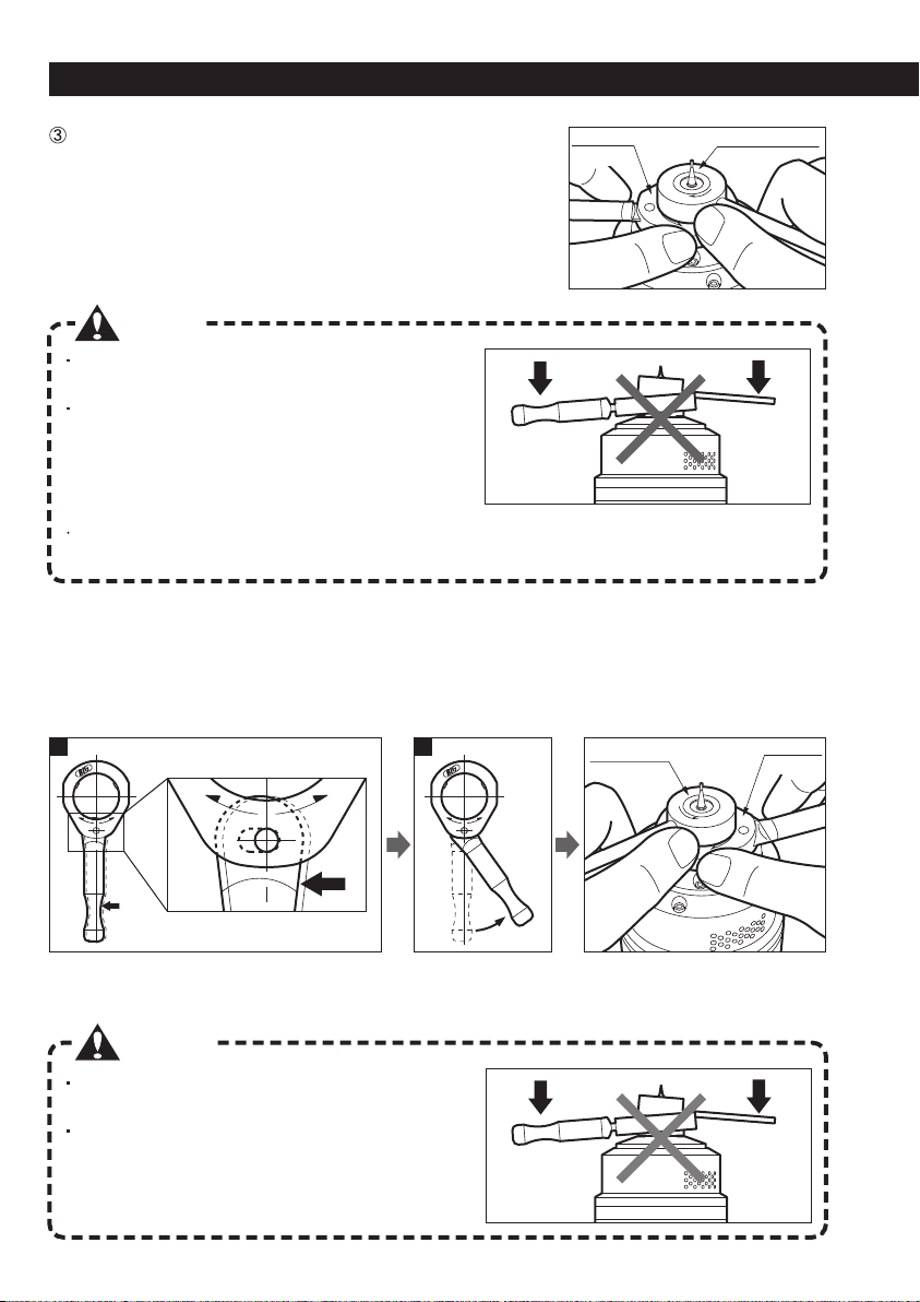
Caution
Be careful to not damage the cutting tool when
inserting the wrench.
Handle the wrenches horizontally. If a force is
applied in the axis direction, the spindle’s bearings
will endure a great load that may rapidly decrease
the lifespan of the spindle.
X-Wrench
MEGA
Wrench
X-Wrench
MEGA
Wrench
UTILIZATION PROCEDURES
[How to remove a cutting tool]
Always respect the recommended tightening torque when clamping a cutting tool.
Over-tightening may worsen the T.I.R. accuracy and damage the collet and the nut.
In case of micro-diameter cutting tools processes, check, after the installation of the cutting tool,
the T.I.R. at the base of the cutting tool’s shank.
Insert the MEGA Wrench on the nut with the “LOCK” seal
facing up and execute the tightening process with both hands.
(Recommended tightening torque: 3N・m)
OPEN
LOCK
MEGA Wrench
(MGR12)
MEGA Wrench
(MGR12)
C
O
L
K
E
O
P
N
X
W
2
7
C
O
L
K
E
O
P
N
X
W
2
7
C
O
L
K
E
O
P
N
21
LOCK
LOCK
OPEN
OPEN
Shift the handle to the “OPEN” side. Shift the handle as
shown in the picture.
Caution
Be careful to not damage the cutting tool when
inserting the wrench.
Handle the wrenches horizontally. If a force is
applied in the axis direction, the spindle’s bearings
will endure a great load that may rapidly decrease
the lifespan of the spindle.
X-Wrench
(XW27)
X-Wrench
(XW27)
To remove a cutting tool, invert “LOCK” and “OPEN” and unfasten the nut with both wrenches
following the same procedures.
5

6
Caution
The cutting tool and the chuck while rotating are extremely dangerous. Do not touch them.
40,000
45,000
50,000
60,000
70,000
80,000
30 sec.
25 sec.
20 sec.
Target speed
(min-1)
RBX5 / RBX5C RBX7 / RBX7C
[Warming-up operation]
[Acceleration time]
It is recommended to execute a warming-up operation
to lubricate with grease the internal parts of the
bearings when the unit is used for the first time or if the
unit is not used for more than 1 week. Perform the
warming-up operation according to the air pressure
indicated on the table.
After have started the air supply, it is necessary to
wait several seconds to reach the selected speed.
Start the process according to the time indicated
on the table. (The table indicates the time
required to reach the target speed after have
adjusted the air pressure and started the air
supply.)
Air pressure for the
warming-up operation
Warming-up time
0.3MPa
More than 10 min.
Time required
for reaching the
target speed
Initial rotation of the air turbine
2
38,000
40,000
43,000
45,000
47,000
48,500
50,000
58,000
62,000
66,000
70,000
73,000
77,000
80,000
0.30
0.35
0.40
0.45
0.50
0.55
0.60
Spindle speed (min-1)
RBX5 / RBX5C RBX7 / RBX7C
Air pressure
(MPa)
Caution
The air pressure should be above 0.3MPa.
If the air pressure is low, the torque will be insufficient and the process unstable.
Spindle speed adjustment
3
It is possible to adjust the speed of the Air Turbine Spindle by controlling the air pressure with a
regulator. Please consult the below table. (The values indicated in the below table are reference
values. Depending on the model, the speed may differ by 5%.)
Please refer to the table indicating the air pressure and the spindle speed on the body of the Air
Turbine Spindle.
7
Caution
Since the air purge does not work when the air is not supplied to the Air Turbine Spindle,
under this situation, coolants, etc. may be able to invade the internal parts. For this reason,
start supplying the air to the turbine before starting the application of coolants and oil mists. In
case of stopping the application of the coolant, please execute the operation continuing to
supply the air to the turbine.
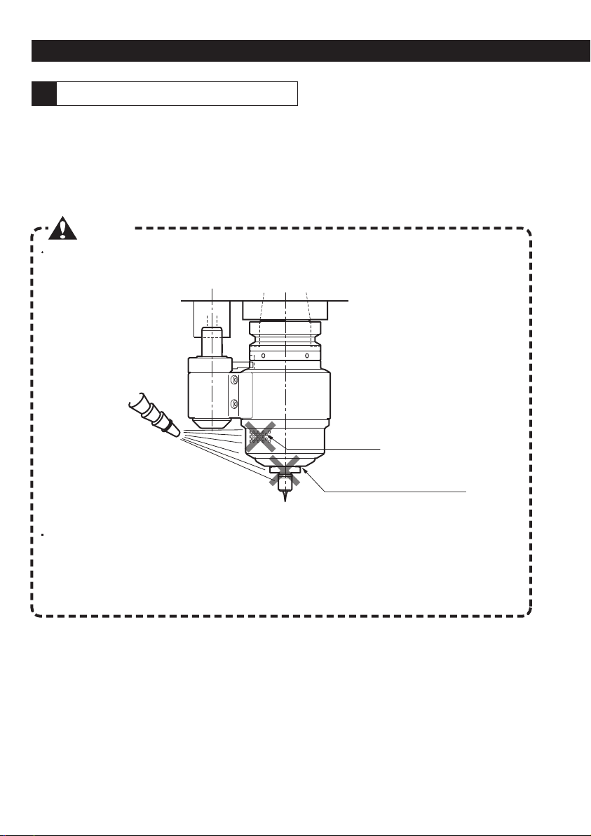
The Air Turbine Spindle, by using air purge for moving the turbine, is built to prevent coolants and oil
mists from invading the internal parts of the holder. However, if the coolant is applied directly on the
spindle body, it may invade its internal parts.
Pay attention to not apply the coolant directly on the body of the Air Turbine Spindle.
Coolants and foreign bodies, by invading the internal parts of the unit, will reduce the lifespan of the
bearings.
Concerning the use of coolants
4
UTILIZATION PROCEDURES
Air vents
Gap between the case and
the flange of the spindle
Pay attention to not apply the coolant directly on the Air Turbine Spindle. In particular
do not apply the coolant on the air vents and on the gap between the case and the
flange of the spindle.
8
BBT30
BBT40
BBT50
15
-
20
45
-
65
85
-
115
BT No. Tightening torque (N m)
Caution
Caution
Do not loosen the 6 red-painted bolts. It may become
cause of damages or worsen the accuracy.
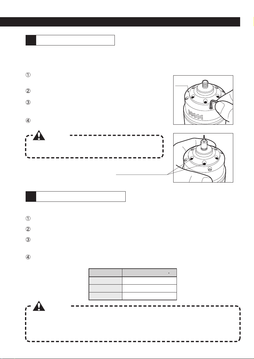
The direction of the air nozzles can be set in 4 directions at 90˚ each. If, due to the emitted air, the
application of the coolant is inadequate, please follow the below procedures to adjust the direction of
the air nozzles.
Loosen the 4 fixing bolts of the muffler case.
(Refer to the below safety notes)
Remove the 4 bolts.
Adjust the direction of the air nozzles by rotating the
muffler case matching the positions of the bolts’ holes.
Re-tight firmly the bolts.
Muffler
case
Never loosen the (6) bolts.
Air nozzles adjustment
5
Pull-stud bolts installation
6
Always respect the recommended torque when clamping the pull-stud bolts. In particular for
BBT30, exceeding the recommended values will easily bulge the taper, due to the thickness of
the small part of the taper. Since, when the Air Turbine Spindle is used, the spindle of the
machine does not rotate, the clamping torque of the pull-stud bolts is a little lower than normal.
Follow the below procedures to install the pull-stud bolts.
Check if the machine and the pull-stud bolts are compatible.
Clean the installation holes of the taper and remove the grease of the pull-stud bolts.
Apply an anti-loosening solution. (Refer to the operation manual of the anti-loosening manufacturer
for details regarding the application method.)
Always use the torque wrench (available on the market) and clamp following the below
recommended torque.
9
INSTALLATION (Side through type)
RBX7
RBX7
RBX5
RBX7
RBX5
80
80
96
100
BBT30
BBT40
BBT50
28
43
58
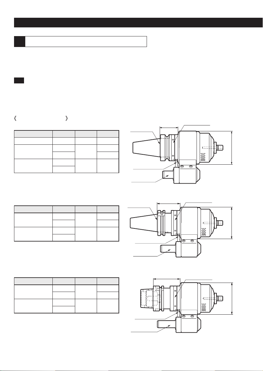
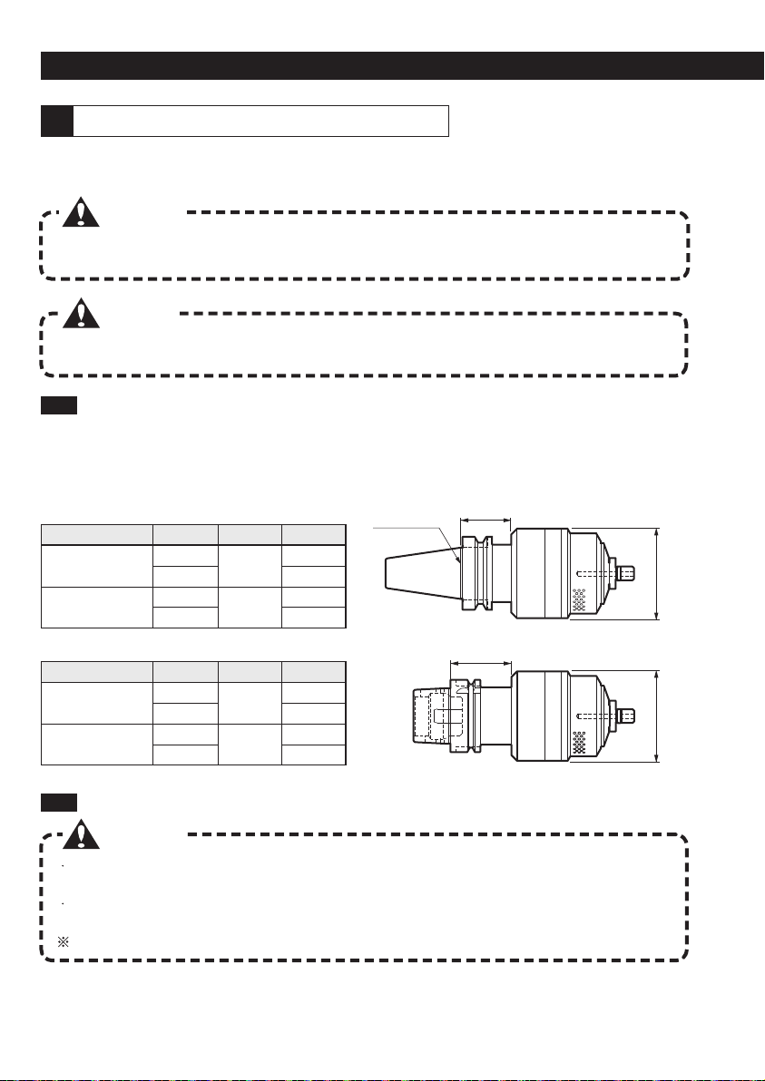
TypeShank Size K1øD
The Air Turbine Spindle is set and shipped following the machine model indicated at the
moment of the purchase and consulting our past results. However, for safety reasons, be
sure to check the following notes before the installation on the machining center.
Use as base the interference values written in the operation manual of the machining center and the
measures of K1and øD of the Air Turbine Spindle to check that there is no interference between the
ATC arm of the machining center and the Air Turbine Spindle. Please inquiry the machine
manufacturer in case of unclear interference.
1-1 ATC arm interference check
Side through type
RBX7
RBX5
RBX7
RBX5
80
96
100
#40
#50
57
62
RBX7
RBX5
RBX7
RBX5
80
96
100
HSK-A63
HSK-A100
67
72
øDøDøD
K1
K1
K1
Gauge line
Indexing ring
Indexing ring
Indexing ring
Installation of the side through type
1
Locating collar
Locating pin
Gauge line
Locating collar
Locating pin
Locating collar
Locating pin
TypeShank Size K1øD
TypeShank Size K1øD
BBT shank
BCV, BDV shank
HSK shank
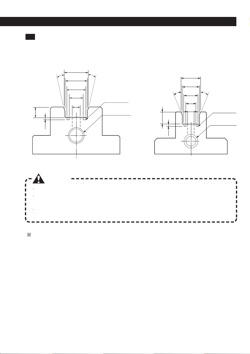
1-2 Locating block of the machine spindle
10
The locating block is necessary for the air supply. Since the measures and the shape of the locating
block depend on the model of the machining center, control, by checking the operation manual,
drawing and materials of the machine that the block is actually suitable for the machine’s spindle.
Caution
A tap hole for plumbing laterally the air is always necessary for the locating block.
When installing the air to the locating block, use an air filter. An air rich with moisture and
foreign particles may damage the bearings.
In case of using the ATC, before installing the Air Turbine Spindle release one time the air
for clean the ditches and the internal parts of the block.
To the customers that currently use our High Jet Holder, High Spindle, etc and
have already installed the locating block in the machines
Even if the locating block for the Air Turbine Spindle and the locating block for the holder of the
High Jet Holder, High Spindle, etc have the same shape, please avoid a shared use. In case of
the Air Turbine Spindle, the air supplied from the locating pin has to be pure. If a locating block
that has used in the past coolants, is used for the Air Turbine Spindle, the coolant invading the
Air Turbine Spindle, may reduce its efficiency and life due rust, etc.
18+0.03
+0.01
19.6±0.02
9±0.1
9±0.1
13±0.02
10˚
10˚
10˚
10˚
1.3
12
ø9.9
ø5
ø6.7
O ring’s ditch
O ring’s ditch
+0.03
+0.01
0
-0.1
ø16.6 0
-0.1
ø12+0.1
0
ø7
+0.1
0
0
-0.1
20
-0.1
For #30
For #40 - #50
PT tap hole
Air supply port
PT tap hole
Air supply port
11
Caution
Be sure to do the checks when performing the manual installation.
If there are errors in the settings, the Air Turbine Spindle may be damaged during the ATC.
INSTALLATION (Side through type)
After the orientation (M19) of the machining center’s spindle, fix the drive key’s position and install
manually the Air Turbine Spindle on the machine. At this time check that the drive key and the
locating pin enter without problems.
Execute the ATC after have checked the procedures from 1-1 (P9) to 1-5 (P11) and the below attention notes.
Caution
Please reduce the ATC speed.The impact with the ATC may damage the tool in case of using
tools with small diameter.
Do not rotate the machine’s spindle at high speed or for a long time when the Air Turbine
Spindle is installed in the machine.
(When the unit is fixed on the case with the locating pin, since it is built to let rotate only the
internal part of the holder even if the machine’s spindle is rotated, high speed and long time
rotations will lead to damages due being stuck, etc.)
It is not a problem to rotate the machine’s spindle for the orientation at the moment of the ATC.
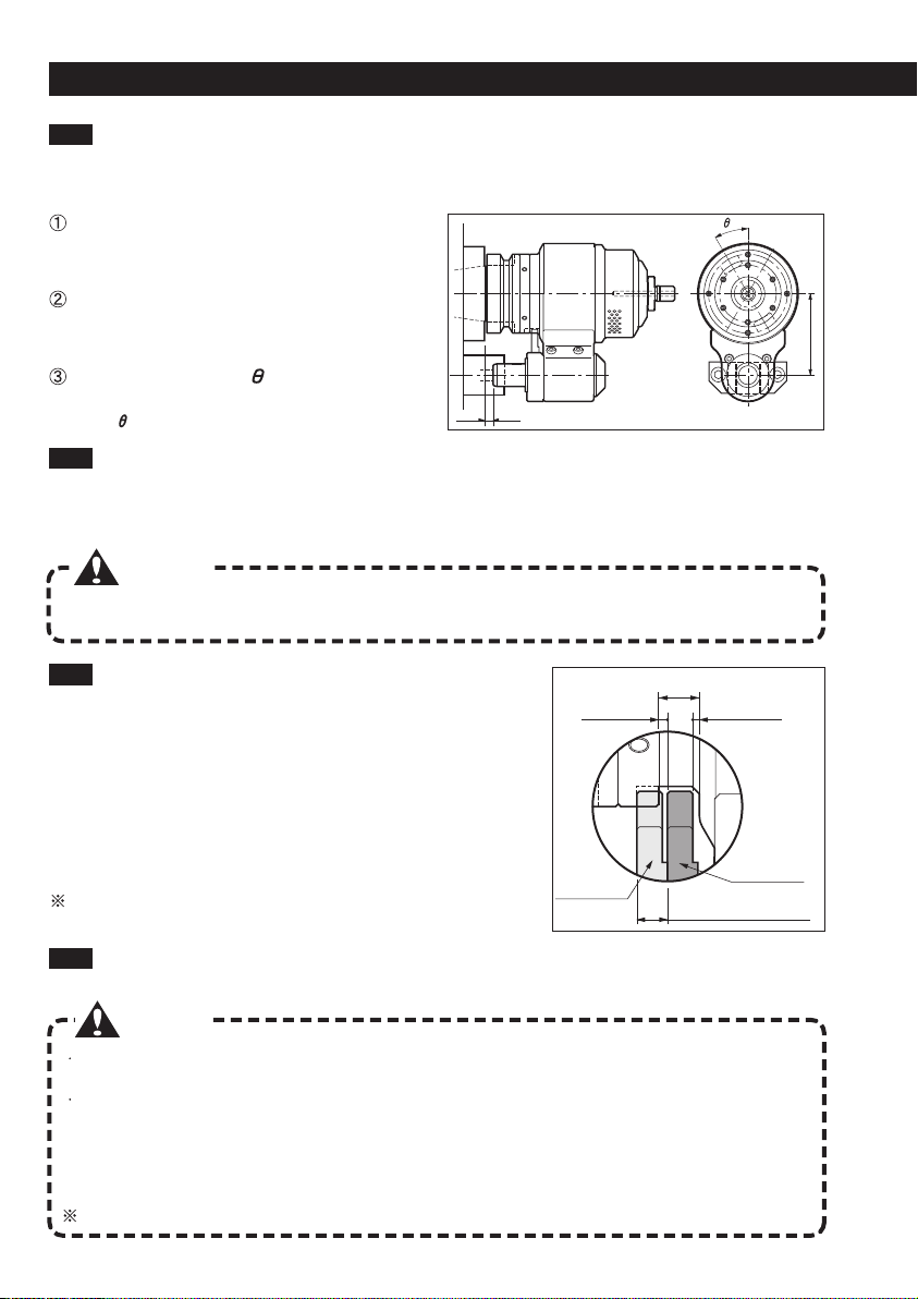
Pay attention that a clutch movement of the locating pin higher
than the prescribed amount (6mm) will exert an eccentric load
on the case and add an anomalous load to the bearings leading
to heat and a reduction of the lifespan. Pay also attention that
a movement of the locating pin inferior to the prescribed
amount will not release the lock mechanism. If the spindle is
rotated in this situation the Air Turbine Spindle may be
damaged. The correct position has a gap of 2mm and 1mm on
each side of the clutch. (See the figure on the right)
Check that the setting measures of the “Inspection sheet” included with the Air Turbine Spindle
match the values of the machine’s spindle nose.
1-3
Please return the product to us since the
modifications cannot be done by the customer.
Please read at P12 “How to adjust the setting
length H” and proceed with the adjustments.
Please read at P13 “How to adjust the setting
angle ” and proceed with the adjustments.
S
H
Gap 8mm
Gap 2mm Gap 1mm
Before the
installation
Settings check
1-4 Checking by actual installing
1-5 Length settings check
1-6 Regarding the ATC
If the pitch S is different
If the setting length H is different
If the setting angle is different
If the gaps differ, please read at P12 “How to adjust the
setting length H” and proceed with the adjustments.
Amount of the clutch
movement 6mm
After the
installation
12
BBT40
BBT50
B(mm)=32-H
B(mm)=47-H
Shank size Length of B
HSK-A63
HSK-A100
B(mm)=56-H
B(mm)=61-H
Shank size Length of B
#40
#50
B(mm)=46-H
B(mm)=51-H
Shank size Length of B
How to remove the locating pin
Keeping pushed the locating pin (to release the lock
mechanism), manually rotate the taper until the tip of the
locating collar is located in the large notch of the indexing
ring. Rotate the locating pin until it is positioned in the large
notch of the indexing ring and pull it out. Also remove at the
same time the locating collar and the spring.
How to calculate the length of the locating pin
Substitute the setting length H of the used machine with the following formula and calculate the
length B of the locating pin.
How to adjust the length of the locating pin
Loosen the set screw of the locating collar then loosen the nut and the locating collar itself.
Adjust the nut and set the pin length to B ±0.3mm (Refer to the above figure).
After the adjustment, fix the nut and tighten the locating
collar. Apply the anti-loosening solution (Toagosei:
Arontight US equivalent) to the set screw of the locating
collar, insert a brass shim and tighten the screw completely
with an L-wrench.
How to install the locating pin
Install the locating pin by inverting the removal procedures.
In case of BBT shanks
In case of BCV, BDV shanks In case of HSK shanks
Locating pin
Nut
Set screw
B(mm)
10 20 30
B
How to adjust the setting length H It is not possible to
adjust the #30 type
Locating
collar
Locating
collar

13
INSTALLATION (Side through type)
Caution
If the 4 lock bolts are not uniformly and gradually clamped, the indexing ring will be loose causing
ATC problems.
Side lock removal
Loosen the 4 lock bolts of the indexing ring.
(Refer to the figure on the right)
Setting angle adjustment
Check that the indexing ring rotates around the
circumference. Adjust the scale of the indexing ring to
the setting angle used on your machine by matching
exactly the line marker on the main body.
(Refer to the figure on the right)
Tightening the side lock
After the adjustment, apply the anti-loosening solution (Toagosei: Arontight US equivalent) to the
lock bolts and tighten firmly and uniformly the 4 lock bolts. In this moment, gradually clamp the 2
opposite locations.
#40, #50 types
Side lock removal
Loosen the 2 lock bolts of the indexing ring.
(Refer to the figure on the right)
+30゜
-
30゜
-
60゜
-
90゜
How to adjust the setting angle
#30type
Line
marker
Lock bolts
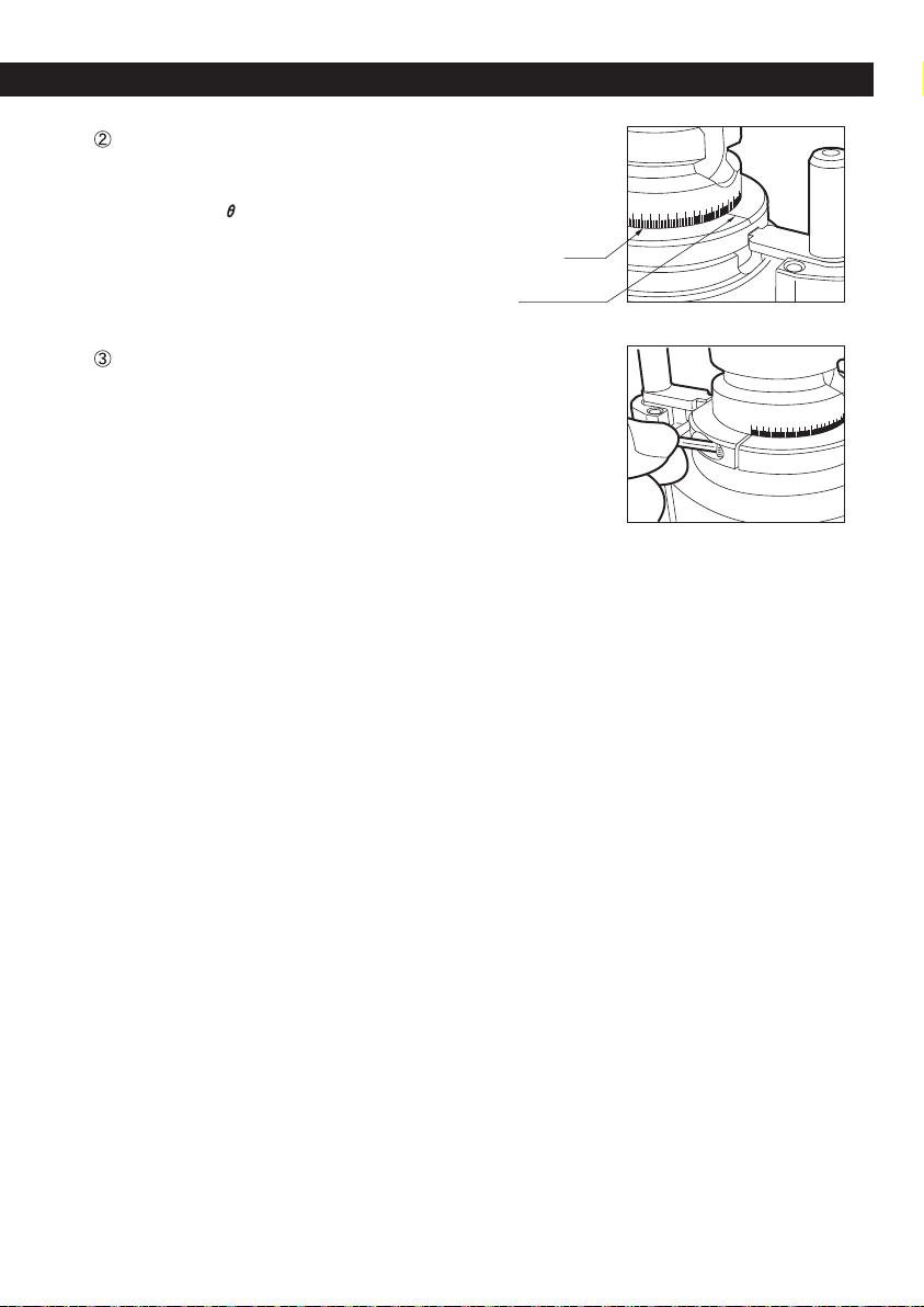
Indexing ring
line marker
14
Setting angle adjustment
Check that the indexing ring rotates around the
circumference. Adjust the scale of the indexing ring to the
setting angle used on your machine by matching exactly
the line marker on the main body.
(Refer to the figure on the right)
Tightening the lock bolts
After the adjustment, apply the anti-loosening solution
(Toagosei: Arontight US equivalent) to the lock bolts and
tighten firmly and uniformly the 2 lock bolts.
Scale
2-1 ATC arm interference check
2-2 Regarding the ATC
15
INSTALLATION (Center through type, Manual type)
Caution
Please reduce the ATC speed. The impact with the ATC may damage the tool in case of
using tools with small diameter.
Do not rotate the machine’s spindle at high speed or for long time when the Air Turbine
Spindle is installed in the machine.
It is not a problem to rotate the machine’s spindle for the orientation at the moment of the ATC.
RBX7C
RBX5C
RBX7C
RBX5C
78
96
78
96
HSK-A63
HSK-A100
53
58
RBX7C
RBX5C
RBX7C
RBX5C
78
96
78
96
BBT40
BBT50
43
53
TypeShank size K1øD
TypeShank size K1øD
BBT shank
HSK shank
øD
K1
K1
øD
Gauge line
For safety reasons, be sure to check the following notes before the installation on the
machining center.
Use as base of the interference values written in the operation manual of the machining center and
the measures of K1and øD of the Air Turbine Spindle to check that there is no interference between
the ATC arm of the machining center and the Air Turbine Spindle. Please inquiry the machine
manufacturer in case of unclear interference.
Installation of the center through type
2
Caution
Do not use it on machines that have previously used coolants, oil mists, etc.
(Foreign bodies invading the holder may reduce its lifespan or cause breakages)
Caution
In case of using BBT, BCV and BDV shanks, please use pull-stud bolts provided with holes
(sold apart).

3-1 Anti-rotation bar installation
3-2 Installation on the machine
16
Warning
Be sure to stop the rotation.
When using the Air Turbine Spindle, it is not necessary to fix it using an anti-rotation bar,
however, if the machine’s spindle is rotated by mistake, this may twist the air tube causing severe
accidents.
Insert, as shown in the figure on the
right, the anti-rotation bar with its flat
part facing up in the anti-rotation block
and perform a side lock.
Make a “stop bar” and install it on the machine surface.
Installation of the manual type
3
Anti-rotation
block
Anti-rotation
bar
Stop bar
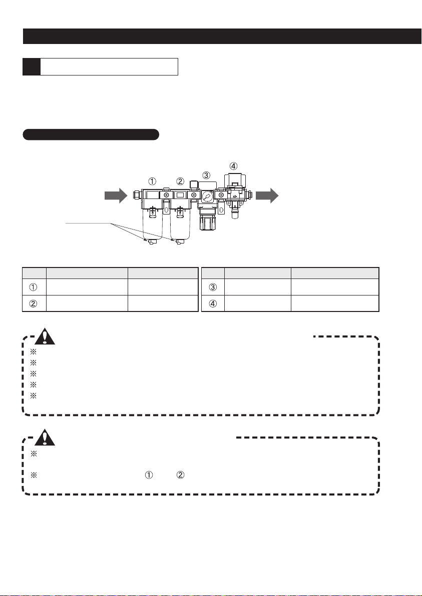
NameName
NumberNumber
FunctionFunction
Do not use air that contains large quantities of drain (moisture, oil, dust).
Install the device vertically in order to have the drain valves pointing downward
Arrange enough space under the “Air filter regulator” for changing the elements and for draining.
Before doing the plumbing, clean the tubes removing chips, coolants and foreign bodies.
Prevent tensional and bending moments on the “Air filter regulator” other than its own weight.
(Pay attention in particular when using pipes like steel pipes, etc., that do not have flexibility.)
Cautions regarding the maintenance
Since the Air Turbine Spindle uses compressed air as driving source, if an air rich with moisture and
foreign bodies is used, the bearings may rust or get stuck reducing the tool life. In order to use pure
air, the following device is recommended. Even when using the center through type, always use a
filter (mesh: 0.01mm or above) to supply pure air from the machine’s spindle.
Mist separator Mesh: 0.3µm
Mesh: 0.01µmMicro mist separator
Precision regulator
ON/OFF valve
Air pressure adjustment
(spindle speed)
Open/close the air
(no-grease type)
Before using the device always check the amount of drain inside the regulator and the dirt of
the plastic cases. If the plastic cases are very dirty clean them using a neutral detergent.
Replace the filter elements and with new ones after 2 years of use or if the air
pressure is lower than 0.1MPa. (Consult P18 Element replacement)
INSTALLATION
Concerning the air supply
4
17
Cautions regarding the installation and the plumbing
IN OUT
Drain valves
Air filter regulator (Model: XF1)
This device is necessary to remove foreign bodies from the air supplied to the spindle
and to regulate the air pressure.
Shop’s air
(Tube diameter:ø10)
To the Air Turbine Spindle
(Tube diameter:ø8)
Warning
Before replacing the elements always check that there is no pressure inside the device.
Warning
After have done the replacement work, please always check that there are no external leaks
and that the functions are adequate before carrying out the installation.
In case of not being able to drain a great volume due to low pressure, the element of the (micro) mist
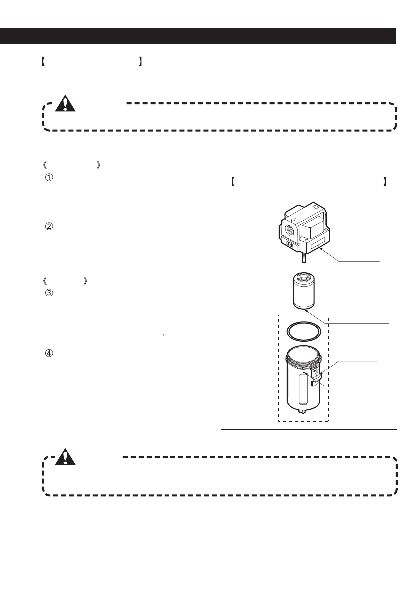
separator is stuck. Replace the element assembly (sold apart) following the below procedures.
Procedures
Case assembly removal
Push down the lock button while pulling
up the case assembly and then rotate it
in one direction for 45° to remove it.
Element removal
Apply round pincers to the cylindrical
part of the element and turn them to the
left for removing the element.
Element installation
Apply round pincers to the cylindrical
part of the element and turn them to the
right for installing the element.
Clamping torque 0.35±0.05 [N m]
Case assembly installation
Insert the case assembly in the body
assembly aligning the respective line
markers and then rotate it in one
direction for 45° (until the lock button
slides up) to mount the case assembly.
Be sure to check that the lock button
is in the upper position.
Body
assembly
Element
assembly
Case
assembly
Line marker
Line marker
Cylindrical part
for the round pincers
Lock button
18
Element replacement
Disassembly
Assembly
Mist separator assembly drawing

No.0217
Caution
Do not apply the anti-rust oil on the body (muffler case, locating pin, etc.) of the unit.
The oil invading the unit may lower the life of the bearings.
Protect the air inlet so that foreign bodies, dust, etc. do not penetrate.
Apply anti-rust oil on the internal and external diameters of the chuck and on the taper shank.
Check that the pull-stud bolts, the internal and external diameters of the chuck and the taper
shank are not affected by rust.
Remove completely the anti-rust oil.
Before connecting the air tube to the unit, release the air to check that moisture, etc. is not
present inside the tube.
Perform a warming-up operation.
It is not necessary to oil the internal parts of the unit. We will grease the unit when doing the
overhaul.
Never disassemble or modify the unit. Otherwise, it will be considered outside the normal
overhaul or repairs.
It is recommended to perform the overhaul after 1 year from the first operation or when the
operation time exceeds 2000 hours. The overhaul is also recommended if the unit is not used
for a long period of time (1 year or more). Return the unit through our distributors for the
overhaul. The overhaul is charged.
Stop immediately the operation and contact us in case of strange noises and nasty smells
coming from the Air Turbine Spindle or in case of strong vibrations.
In addition do not continue to operate with strong vibrations (chattering process).
19
Long period storage and re-use
1
Maintenance
2
OTHER
In case of storing the device for a long period of time
Greasing
Disassembly and modifications
Overhaul
In case of strange noises, nasty smells and vibrations
In case of re-use the unit after a long period of storage
EXPORT DEPARTMENT
TEL (+81)-72-982-8277
E-mail [email protected]
This manual suits for next models
3
Table of contents
Other BIG Industrial Equipment manuals

BIG
BIG Point Master Pro User manual

BIG
BIG BBT40 User manual

BIG
BIG Point Master Pro PMPC Series User manual

BIG
BIG PLP-BBT30 User manual

BIG
BIG Base Master Mini User manual

BIG
BIG C-Cutter Universal Type User manual

BIG
BIG FCR User manual

BIG
BIG Base Master Mini User manual

BIG
BIG HSK-A63 User manual

BIG
BIG BBT40-SSL -135 Series User manual


