Binder Solid.Line BD-S 56 User manual

Issue 03/2022 Art. No. 7001-0359
Operating Manual
Solid.Line™
BD
-S / BD-S-UL (E1)
Incubators with natural convection
ED
-S / ED-S-UL (E1)
Drying and heating ovens with natural
convection
FD
-S / FD-S-UL (E1)
Drying and heating ovens with forced con-
vection
with R-S microprocessor temperature controller
Model
Model version
Art. No.
BD-S 56 BDS056-230V 9090-0016-
BD-S-UL 56 BDS056UL-120V 9090-0017
BD-S 115 BDS115-230V 9090-0022
BD-S-UL 115 BDS115UL-120V 9090-0023
ED-S 56 EDS056-230V 9090-0014
ED-S-UL 56 EDS056UL-120V 9090-0015
ED-S 115 EDS115-230V 9090-0020
ED-S-UL 115 EDS115UL-120V 9090-0021
FD-S 56 FDS056-230V 9090-0018
FD-S-UL 56 FDS056UL-120V 9090-0019
FD-S 115 FDS115-230V 9090-0024
FD-S-UL 115 FDS115UL-120V 9090-0025
BINDER GmbH
Address: Post office box 102, 78502 Tuttlingen, Germany Phone: +49 7462 2005 0
Fax: +49 7462 2005 100 Internet: http://www.binder-world.com
E-mail: info@binder-world.com Service Hotline: +49 7462 2005 555
Service Fax: +49 7462 2005 93 555 Service E-Mail: customerservice@binder-world.com
Service Hotline USA: +1 866 885 9794 or +1 631 224 4340 x3
Service Hotline Asia Pacific: +852 390 705 04 or +852 390 705 03
Service Hotline Russia and CIS: +7 495 988 15 16

BD-S / BD-S-UL, ED-S / ED-S-UL, FD-S / FD-S-UL (E1) 03/2022 page 2/60
Content
1. SAFETY.................................................................................................................. 4
1.1 Personnel Qualification .......................................................................................................................4
1.2 Operating manual................................................................................................................................4
1.3 Legal considerations ...........................................................................................................................4
1.3.1 Intellectual property ...................................................................................................................5
1.4 Structure of the safety instructions......................................................................................................5
1.4.1 Signal word panel......................................................................................................................5
1.4.2 Safety alert symbol ....................................................................................................................6
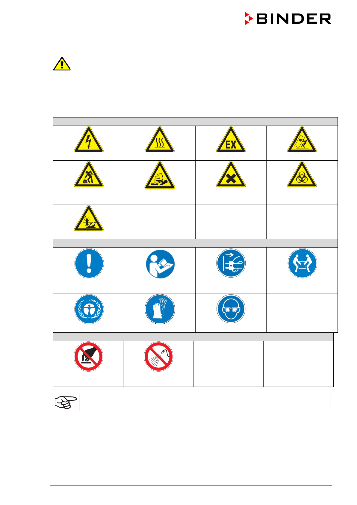
1.4.3 Pictograms.................................................................................................................................6
1.4.4 Word message panel structure .................................................................................................7
1.5 Localization / position of safety labels on the chamber ......................................................................7
1.6 Type plate............................................................................................................................................8
1.7 General safety instructions on installing and operating the chambers ...............................................9
1.8 Intended use .....................................................................................................................................10
1.9 Foreseeable Misuse..........................................................................................................................12
1.10 Residual Risks ..................................................................................................................................12
2. CHAMBER DESCRIPTION .................................................................................. 14
2.1 Chamber overview ............................................................................................................................14
2.2 Triangular instrument panel ..............................................................................................................15
3. COMPLETENESS OF DELIVERY, TRANSPORTATION, STORAGE, AND
INSTALLATION.................................................................................................... 16
3.1 Unpacking, and checking equipment and completeness of delivery ................................................16
3.2 Guidelines for safe lifting and transportation.....................................................................................16
3.3 Storage..............................................................................................................................................17
3.4 Location of installation and ambient conditions ................................................................................17
4. INSTALLATION.................................................................................................... 18
4.1 Installing the racks ............................................................................................................................18
4.2 Connection to an exhaust/ventilation system (optional) ...................................................................18
4.3 Electrical connection .........................................................................................................................19
5. R-S CONTROLLER OVERVIEW.......................................................................... 20
5.1 Menu structure overview ...................................................................................................................21
6. START UP ............................................................................................................ 21
6.1 Adjusting air change..........................................................................................................................21
7. TEMPERATURE SET -POINT ENTRY ................................................................ 22
8. SELECTING THE TEMPERATURE UNIT............................................................ 22
8.1 Setting the temperature unit..............................................................................................................22
9. OVERTEMPERATURE PROTECTION ................................................................ 23
9.1 Overtemperature protective device (class 1) ....................................................................................23
9.2 Safety controller ................................................................................................................................23
9.2.1 Setting the safety controller.....................................................................................................23
9.2.2 Alarm message and proceeding in case of an alarm ..............................................................24
10. TIMER FUNCTION “DELAYED OFF” ................................................................. 25
10.1 Setting the timer run-time..................................................................................................................25

BD-S / BD-S-UL, ED-S / ED-S-UL, FD-S / FD-S-UL (E1) 03/2022 page 3/60
11. CLEANING AND DECONTAMINATION .............................................................. 25
11.1 Cleaning ............................................................................................................................................26
11.2 Decontamination / chemical disinfection...........................................................................................27
12. MAINTENANCE AND SERVICE, TROUBLESHOOTING, REPAIR, TESTING... 28
12.1 General information, personnel qualification.....................................................................................28
12.2 Maintenance intervals, service..........................................................................................................29
12.3 Simple troubleshooting......................................................................................................................29
12.4 Sending the chamber back to BINDER GmbH .................................................................................31
13. DISPOSAL............................................................................................................ 31
13.1 Disposal of the transport packing......................................................................................................31
13.2 Decommissioning..............................................................................................................................31
13.3 Disposal of the chamber in the Federal Republic of Germany .........................................................32
13.4 Disposal of the chamber in the member states of the EU except for the Federal Republic of Germany
..........................................................................................................................................................33
13.5 Disposal of the chamber in non-member states of the EU ...............................................................34
14. TECHNICAL DESCRIPTION................................................................................ 34
14.1 Factory calibration and adjustment ...................................................................................................34
14.2 Definition of usable volume...............................................................................................................34
14.3 Over current protection .....................................................................................................................34
14.4 Technical data...................................................................................................................................35
14.5 Equipment and options (extract) .......................................................................................................37
14.6 Accessories and spare parts (extract) ..............................................................................................37
14.7 Dimensioned drawings......................................................................................................................38
14.7.1 BD-S / BD-S-UL 56..................................................................................................................38
14.7.2 BD-S / BD-S-UL 115................................................................................................................39
14.7.3 ED-S / ED-S-UL 56..................................................................................................................40
14.7.4 ED-S / ED-S-UL 115................................................................................................................41
14.7.5 FD-S / FD-S-UL 56 ..................................................................................................................42
14.7.6 FD-S / FD-S-UL 115 ................................................................................................................43
15. CERTIFICATES AND DECLARATIONS OF CONFORMITY............................... 44
15.1 EU Declaration of Conformity for BD-S.............................................................................................44
15.2 EU Declaration of Conformity for ED-S.............................................................................................46
15.3 EU Declaration of Conformity for FD-S.............................................................................................48
15.4 Certificate for the GS mark of conformity of the “VDE Prüf- und Zertifizierungsinstitut” (Testing and
Certification Institute of the Association for Electrical, Electronic and Information Technologies) ...50
15.5 Certificate of UL Compliance from Underwriters Laboratories Inc.®.................................................54
16. CONTAMINATION CLEARANCE CERTIFICATE ............................................... 55
16.1 For chambers located outside the USA and Canada .......................................................................55
16.2 For chambers located in the USA and Canada ................................................................................58

BD-S / BD-S-UL, ED-S / ED-S-UL, FD-S / FD-S-UL (E1) 03/2022 page 4/60
Dear customer,
For the correct operation of the chambers, it is important that you read this operating manual completely
and carefully and observe all instructions as indicated. Failure to read, understand and follow the instruc-
tions may result in personal injury. It can also lead to damage to the chamber and/or poor equipment per-
formance
1. Safety
1.1 Personnel Qualification
The chamber must only be installed, tested, and started up by personnel qualified for assembly, startup,
and operation of the chamber. Qualified personnel are persons whose professional education, knowledge,
experience and knowledge of relevant standards allow them to assess, carry out, and identify any potential
hazards in the work assigned to them. They must have been trained and instructed, and be authorized, to
work on the chamber.
The chamber should only be operated by laboratory personnel especially trained for this purpose and fa-
miliar with all precautionary measures required for working in a laboratory. Observe the national regulations
on minimum age of laboratory personnel.
1.2 Operating manual
This operating manual is part of the components of delivery. Always keep it handy for reference in the
vicinity of the chamber. If selling the unit, hand over the operating manual to the purchaser.
To avoid injuries and damage observe the safety instructions of the operating manual. Failure to follow
instructions and safety precautions can lead to significant risks.
DANGER
Dangers due to failure to observe the instructions and safety precautions.
Serious injuries and chamber damage. Risk of death.
Observe the safety instructions in this Operating Manual.
Follow the operating procedures in this Operating Manual.
Carefully read the complete operating instructions of the chamber prior to installing and
using the chamber.
Keep the operating manual for future reference
Make sure that all persons who use the chamber and its associated work equipment have
read and understood the Operating Manual.
This Operating Manual is supplemented and updated as needed. Always use the most recent version of
the Operating Manual. When in doubt, call the BINDER Service Hotline for information on the up-to-date-
ness and validity of this Operating Manual.
1.3 Legal considerations
This operating manual is for informational purposes only. It contains information for correct and safe in-
stalling, start-up, operation, decommissioning, cleaning and maintenance of the product. Note: the contents
and the product described are subject to change without notice.
Understanding and observing the instructions in this operating manual are prerequisites for hazard-free use
and safety during operation and maintenance. Images are to provide basic understanding. They may devi-
ate from the actual version of the chamber. The actual scope of delivery can, due to optional or special
design, or due to recent technical changes, deviate from the information and illustrations in these instruc-
tions this operating manual. In no event shall BINDER be held liable for any damages, direct or incidental
arising out of or related to the use of this manual.

BD-S / BD-S-UL, ED-S / ED-S-UL, FD-S / FD-S-UL (E1) 03/2022 page 5/60
This operating manual cannot cover all conceivable applications. If you would like additional information,
or if special problems arise that are not sufficiently addressed in this manual, please ask your dealer or
contact us directly, e.g. by phone at the number located on page one of this manual
Furthermore, we emphasize that the contents of this operating manual are not part of an earlier or existing
agreement, description, or legal relationship, nor do they modify such a relationship. All obligations on the
part of BINDER derive from the respective purchase contract, which also contains the entire and exclusively
valid statement of warranty administration and the general terms and conditions, as well as the legal regu-
lations valid at the time the contract is concluded. The statements in this manual neither augment nor
restrict the contractual warranty provisions.
1.3.1 Intellectual property
Trademark Information: All BINDER trademarks relating to products or service, as well as trade names,
logos and product names used on the website, products and documents of BINDER company are trade-
marks or registered trademarks of BINDER company (including BINDER GmbH, BINDER Inc.) in the U.S.
and other countries and communities of states. This includes word marks, position marks, word/figurative
marks, design configurations, figurative marks, and design patents.
Patent Information: BINDER products, categories of products, and accessories may be covered by one
or more patents and/or utility models in the U.S. and other countries and communities of states. Additional
patent applications may also be pending in the U.S. and other countries and communities of states.
Please visit www.binder-world.com for more information.
1.4 Structure of the safety instructions
In this operating manual, the following safety definitions and symbols indicate dangerous situations follow-
ing the harmonization of ISO 3864-2 and ANSI Z535.6.
1.4.1 Signal word panel
Depending on the probability of serious consequences, potential dangers are identified with a signal word,
the corresponding safety color, and if appropriate, the safety alert symbol.
DANGER
Indicates an imminently hazardous situation that, if not avoided, will result in death or serious
(irreversible) injury.
WARNING
Indicates a potentially hazardous situation which, if not avoided, could result in death or serious
(irreversible) injury
CAUTION
Indicates a potentially hazardous situation which, if not avoided, may result in moderate or minor
(reversible) injury
NOTICE
Indicates a potentially hazardous situation which, if not avoided, may result in damage to the product
and/or its functions or of a property in its proximity.

BD-S / BD-S-UL, ED-S / ED-S-UL, FD-S / FD-S-UL (E1) 03/2022 page 6/60
1.4.2 Safety alert symbol
Use of the safety alert symbol indicates a risk of injury.
Observe all measures that are marked with the safety alert symbol in order to avoid death or
injury.
1.4.3 Pictograms
Warning signs
Electrical hazard
Hot surface
Explosive atmosphere
Stability hazard
Lifting hazard
Risk of corrosion and / or
chemical burns
Harmful substances
Biohazard
Pollution Hazard
Mandatory action signs
Mandatory regulation
Read operating
instructions
Disconnect the power
plug
Lift with several persons
Environment protection
Wear protective gloves
Wear safety goggles
Prohibition signs
Do NOT touch
Do NOT spray with
water
Information to be observed in order to ensure optimum function of the product.

BD-S / BD-S-UL, ED-S / ED-S-UL, FD-S / FD-S-UL (E1) 03/2022 page 7/60
1.4.4 Word message panel structure
Type / cause of hazard.
Possible consequences.
∅Instruction how to avoid the hazard: prohibition.
Instruction how to avoid the hazard: mandatory action.
Observe all other notes and information not necessarily emphasized in the same way, in order to avoid
disruptions that could result in direct or indirect injury or property damage.
1.5 Localization / position of safety labels on the chamber
The following labels are located on the chamber:
Pictograms (Warning signs)
Service label
Hot surface
•ED-S / ED-S-UL, FD-S / FD-S-UL: outer cham-
ber door
•BD-S / BD-S-UL: on the glass door handle
•On the exhaust air flap
Read operating manual
•UL chamber: outer chamber door
ED-S 56, FD-S 56
ED-S-UL 56, FD-S-UL 56
Figure 1: Position of labels on the chamber front (examples)
Keep safety labels complete and legible.
Replace safety labels that are no longer legible. Contact BINDER Service for these replacements.

BD-S / BD-S-UL, ED-S / ED-S-UL, FD-S / FD-S-UL (E1) 03/2022 page 8/60
1.6 Type plate
The type plate is located on the left-hand side of the chamber, bottom right-hand.
Figure 2: Type plate (example BD-S 115-230V regular chamber)
Indications of the type plate (example)
Indication
Information
BINDER
Manufacturer: BINDER GmbH
BD-S 115
Model designation
Incubator
Chamber name: Incubator
Drying and heating oven
Chamber name: Drying and heating oven
Serial No.
000000000000
Serial No of the chamber
Built
2020
Year of construction
Nominal temperature
70 °C
158 °F
Nominal temperature
IP protection
20
IP type of protection acc. to EN 60529
Temp. safety device
DIN 12880
Temperature safety device acc. to standard DIN 12880
Class
3.1
Class of temperature safety device
Art. No.
9090-0022
Art. no. of the chamber
Project No.
---
Optional: Special application acc. to project no.
1,30 kW
Nominal power
5,7 A
Nominal current
230 V / 50 Hz
Nominal voltage +/- 10%
at the indicated power frequency
230 V / 60 Hz
1 N ~
Current type
Symbols on the type plate
Symbol Valid for Information
All chambers CE conformity marking
All chambers
Electrical and electronic equipment manufactured / placed
on the market in the EU after 13 August 2005 and to be dis-
posed of in a separate collection according to Directive
2012/19/EU on waste electrical and electronic equipment
(WEEE).
Not for UL chambers
GS mark of conformity of the “VDE Prüf- und Zertifizier-
ungsinstitut” (Testing and Certification Institute of the Asso-
ciation for Electrical, Electronic and Information Technolo-
gies
Not for UL chambers
The chamber is certified according to Customs Union Tech-
nical Regulation (CU TR) for the Eurasian Economic Union
(Russia, Belarus, Armenia, Kazakhstan Kyrgyzstan).
Nominal temp.
70 °C
0,35 kW / 1,6 A
158 °F
230 V / 50 Hz
IP protection
20
230 V / 60 Hz
Safety device
DIN 12880
1 N ~
Class 3.1
Art. No.
9090-0022
Project No.
Built
2020
Drying and heating oven
BINDER GmbH
Im Mittleren Ösch 5
78532 Tuttlingen / Germany
www.binder-world.com
BD-S 115
E1
Serial No. 00000000000000
Made in Germany

BD-S / BD-S-UL, ED-S / ED-S-UL, FD-S / FD-S-UL (E1) 03/2022 page 9/60
Symbol Valid for Information
UL chambers only
The chamber is certified by Underwriters Laboratories Inc.®ac-
cording to the following standards:
•UL 61010-2-10
•CAN/CSA-C22.2 No. 61010-2-10
1.7 General safety instructions on installing and operating the chambers
With regard to operating the chambers and to the installation location, please observe the local and national
regulations relevant for your country (for Germany: DGUV guidelines 213-850 on safe working in laborato-
ries, issued by the employers’ liability insurance association).
BINDER GmbH is only responsible for the safety features of the chamber provided skilled electricians or
qualified personnel authorized by BINDER perform all maintenance and repair, and if components relating
to chamber safety are replaced in the event of failure with original spare parts.
To operate the chamber, use only original BINDER accessories or accessories from third-party suppliers
authorized by BINDER. The user is responsible for any risk caused by using unauthorized accessories.
NOTICE
Danger of overheating due to lack of ventilation.
Damage to the chamber.
∅Do NOT install the chamber in unventilated recesses.
Ensure sufficient ventilation for dispersal of the heat.
Observe the prescribed minimum distances when installing the chamber (chap. 3.4)
Do not install or operate the chamber in hazardous locations.
DANGER
Danger of explosion due to combustible dusts or explosive mixtures in the vicinity
of the chamber.
Serious injury or death from burns and / or explosion pressure.
∅Do NOT operate the chamber in potentially explosive areas.
KEEP combustible dust or air-solvent mixtures AWAY from the chamber.
The chamber does not dispose of any measures of explosion protection.
DANGER
Danger of explosion due to introduction of flammable or explosive substances in
the chamber.
Serious injury or death from burns and / or explosion pressure.
∅Do NOT introduce any substance into the chamber which is combustible or explosive at
working temperature.
∅Do NOT introduce any combustible dust or air-solvent mixture in the inner chamber.
Any solvent contained in the charging material must not be explosive or inflammable. I.e., irrespective of
the solvent concentration in the steam room, NO explosive mixture with air must form. The temperature
inside the chamber must lie below the flash point or below the sublimation point of the charging material.
Familiarize yourself with the physical and chemical properties of the charging material, as well as the con-
tained moisture constituent and its behavior with the addition of heat energy.
Familiarize yourself with any potential health risks caused by the charging material, the contained moisture
constituent or by reaction products that may arise during the temperature process. Take adequate
measures to exclude such risks prior to putting the chamber into operation.
LABORATORY EQUIPMENT
43KM

BD-S / BD-S-UL, ED-S / ED-S-UL, FD-S / FD-S-UL (E1) 03/2022 page 10/60
DANGER
Electrical hazard by water entering the chamber.
Deadly electric shock.
∅The chamber must NOT become wet during operation, cleaning, or maintenance.
∅Do NOT install the chamber in damp areas or in puddles.
Set up the chamber in a way that it is splash-proof.
The chambers were produced in accordance with VDE regulations and were routinely tested in accordance
to VDE 0411-1 (IEC 61010-1).
During and shortly after operation, the temperature of the inner surfaces almost equals the set-point. The
glass doors and glass door handles (BD-S / BD-S-UL), inner chamber, exhaust air flap, door window (op-
tion), and the door gaskets will become hot during operation.
CAUTION
Danger of burning by touching hot chamber parts during operation.
Burns.
∅Do NOT touch the glass doors, inner surfaces, exhaust air flap, door window, access
ports, door gaskets, or the charging material during operation.
∅FD-S / FD-S-UL: Do not place the power cable over the door gap when the chamber is
hot after operation.
1.8 Intended use
Observing the instructions in this operating manual and conducting regular maintenance
work (chap. 13) is part of the intended use.
Any use of the chambers that does not comply with the requirements specified in this Operating
Manual shall be considered improper use.
Other applications than those described in this chapter are not approved.
Use
The chambers are suitable for exact tempering of harmless materials and for drying and heat treatment of
solid or pulverized charging material, as well as bulk material, using the supply of heat. They can be used
to dry e.g. glassware, and for warm storage of liquids in containers.
Because of their precise temperature accuracy the incubators BD-S / BD-S-UL are especially useful for
incubation of cultures at a standard temperature of 37 °C / 98.6 °F.
Do NOT use the chamber for drying processes when large quantities of vapor would form and result in
condensation.
Requirements for the chamber load
A solvent content must not be explosive or flammable. A mixture of any component of the charging material
with air must NOT be explosive. The operating temperature must lie below the flash point or below the
sublimation point of the charging material. Any component of the charging material must NOT be able to
release toxic gases.
The charging material shall not contain any corrosive ingredients that may damage the machine compo-
nents. Such ingredients include in particular acids and halides. Any corrosive damage caused by such
ingredients is excluded from liability by BINDER GmbH.

BD-S / BD-S-UL, ED-S / ED-S-UL, FD-S / FD-S-UL (E1) 03/2022 page 11/60
The chamber does not dispose of any measures of explosion protection.
DANGER
Explosion or implosion hazard and danger of poisoning through the introduction of
unsuitable loading material.
Poisoning. Serious injury or death from burns and / or explosion pressure.
∅Do NOT introduce any substance combustible or explosive at working temperature into
the chamber, in particular no energy sources such as batteries or lithium-ion batteries.
∅NO explosive dust or air-solvent mixture in the inner chamber.
∅Do NOT introduce any substance which could lead to release of toxic gases.
Contamination of the chamber by toxic, infectious or radioactive substances must be prevented
WARNING
Danger of intoxication and infection through contamination of the chamber with
toxic, infectious or radioactive substances.
Damages to health.
Protect the interior of the chamber from contamination by toxic, infectious or radioactive
substances.
Take suitable protective measures when introducing and removing toxic, infectious or
radioactive material
In case of foreseeable use of the device there is no risk for the user through the integration of the chamber
into systems or by special environmental or operating conditions in the sense of EN 61010-1:2010. For this,
the intended use of the chamber and all its connections must be observed.
Medical devices
The chambers are not classified as medical devices as defined by the Medical Device Directive 93/42/EEC
and Regulation (EU) No 2017/745.
Due to the special demands of the Medical Device Directive (MDD), these chambers are not
qualified to perform sterilization of medical devices as defined by the directive 93/42/EWG.
Personnel Requirements
Only trained personnel with knowledge of the Operating Manual can set up and install the chamber, start it
up, operate, clean, and take it out of operation. Service and repairs call for further technical requirements
(e.g. electrical know-how), as well as knowledge of the service manual.
Installation site requirements
The chambers are designed for setting up inside a building (indoor use).
The requirements described in the Operating Manual for installation site and ambient conditions (chap. 3.4)
must be met.
WARNING: If customer should use a BINDER chamber running in non-supervised continu-
ous operation, we strongly recommend in case of inclusion of irrecoverable specimen or
samples to split such specimen or samples and store them in at least two chambers, if this is
feasible.

BD-S / BD-S-UL, ED-S / ED-S-UL, FD-S / FD-S-UL (E1) 03/2022 page 12/60
1.9 Foreseeable Misuse
Other applications than those described in chap. 1.8 are not approved.
This expressly includes the following misuses (the list is not exhaustive), which pose risks despite the
inherently safe construction and existing technical safety equipment:
•Non-observance of Operating Manual
•Non-observance of information and warnings on the chamber (e.g. control unit messages, safety iden-
tifiers, warning signals)
•Installation, startup, operation, maintenance and repair by untrained, insufficiently qualified, or unau-
thorized personnel
•Missed or delayed maintenance and testing
•Non-observance of traces of wear and tear
•Insertion of materials excluded or not permitted by this Operating Manual.
•Non-compliance with the admissible parameters for processing the respective material.
•Installation, testing, service or repair in the presence of solvents
•Installation of replacement parts and use of accessories and operating resources not specified and au-
thorized by the manufacturer
•Bypassing or changing protective systems, operation of the chamber without the designated protective
systems
•Non-observance of messages regarding cleaning and disinfection of the chamber.
•Spilling water or cleaning agent on the chamber, water penetrating into the chamber during operation,
cleaning or maintenance.
•Cleaning activity while the chamber is turned on.
•Operation of the chamber with a damaged housing or damaged power cord
•Continued operation of the chamber during an obvious malfunction
•Insertion of objects, particularly metallic objects, in louvers or other openings or slots on the chamber
•Human error (e.g. insufficient experience, qualification, stress, exhaustion, laziness)
To prevent these and other risks from incorrect operation, it is recommended the operator issue operating
instructions and standard operating procedures (SOPs).
1.10 Residual Risks
The unavoidable design features of a chamber, as well as its proper field of application, can also pose risks,
even during correct operation. These residual risks include hazards which, despite the inherently safe de-
sign, existing technical protective equipment, safety precautions and supplementary protective measures,
cannot be ruled out.
Messages on the chamber and in the Operating Manual warn of residual risks. The consequences of these
residual risks and the measures required to prevent them are listed in the Operating Manual. Moreover, the
operator must take measures to minimize hazards from unavoidable residual risks. This includes, in partic-
ular, issuing operating instructions.
The following list summarizes the hazards against which this Operating Manual and the Service Manual
warn, and specifies protective measures at the appropriate spots:
Unpacking, Transport, Installation
•Sliding or tilting the chamber
•Setup of the chamber in unauthorized areas
•Installation of a damaged chamber

BD-S / BD-S-UL, ED-S / ED-S-UL, FD-S / FD-S-UL (E1) 03/2022 page 13/60
•Installation of a chamber with damaged power cord
•Inappropriate site of installation
•Missing protective conductor connection
Normal operation
•Assembly errors
•Contact with hot surfaces on the housing
•Contact with hot surfaces in the interior and inside of doors
•Emission of non-ionizing radiation from electrical operating resources
•Contact with live parts in normal state
Cleaning and Decontamination
•Penetration of water into the chamber
•Inappropriate cleaning and decontamination agents
•Enclosure of persons in the interior
Malfunction and Damage
•Continued operation of the chamber during an obvious malfunction or outage of the heating
•Contact with live parts during error status
•Operation of a unit with damaged power cord
Maintenance
•Maintenance work on live parts.
•Execution of maintenance work by untrained/insufficiently qualified personnel
•Electrical safety analysis during annual maintenance not performed
Trouble-shooting and Repairs
•Non-observance of warning messages in the Service Manual
•Trouble-shooting of live parts without specified safety measures
•Absence of a plausibility check to rule out erroneous inscription of electrical components
•Performance of repair work by untrained/insufficiently qualified personnel
•Inappropriate repairs which do not meet the quality standard specified by BINDER
•Use of replacement parts other than BINDER original replacement parts
•Electrical safety analysis not performed after repairs

BD-S / BD-S-UL, ED-S / ED-S-UL, FD-S / FD-S-UL (E1) 03/2022 page 14/60
2. Chamber description
BINDER incubators BD-S / BD-S-UL and drying and heating ovens ED-S / ED-S-UL and FD-S / FD-S-UL
are equipped with an electronic PID-controller with digital display.
The incubators BD-S / BD-S-UL indicate the temperature with an accuracy of a tenth of a
degree.
The drying and heating ovens ED-S / ED-S-UL and FD-S / FD-S-UL indicate the tempera-
ture with an accuracy of one degree.
All chambers are heated electrically. Incubators BD-S / BD-S-UL and drying and heating ovens ED-S / ED-
S-UL are ventilated naturally. Drying and heating ovens FD-S / FD-S-UL are ventilated by fan-assisted,
forced-air circulation.
The concept of air conduction guarantees high level of spatial and time-based temperature precision,
thanks to the direct and distributed air circulation into the interior. With FD-S / FD-S-UL, the fan supports
exact attainment and maintenance of the desired temperature accuracy.
The chambers are regularly equipped with an overtemperature safety device class 1 acc. to DIN12880:2007
and with an overtemperature safety controller (overtemperature temperature safety device class 2 (ED-S /
ED-S-UL, FD-S / FD-S-UL) or class 3.1(BD-S / BD-S-UL) acc. to DIN12880:2007), see chap. 8.
Material: The inner chamber and the inside of the doors are made of stainless steel V2A (German material
no. 1.4016, US equivalent AISI 430). Drying and heating ovens ED-S / ED-S-UL and FD-S / FD-S-UL:
When operating the chambers at temperatures above 150 °C / 302 °F, the impact of the oxygen in the air
may cause discoloration of the metallic surfaces (yellowish-brown or blue) by natural oxidation processes.
These colorations are harmless and will in no way impair the function or quality of the chamber.
All chamber functions are easy and comfortable to use thanks to their clear arrangement. Major features
are easy cleaning of all chamber parts and avoidance of undesired contamination.
Temperature ranges see technical data (chap. 16.4).
2.1 Chamber overview
Figure 3: Chamber overview, closed chamber
(2)
(1)
(2a)
(3a)
(3)

BD-S / BD-S-UL, ED-S / ED-S-UL, FD-S / FD-S-UL (E1) 03/2022 page 15/60
Figure 4: Chamber overview, open chamber with glass door (BD-S / BD-S-UL)
(1) Triangular instrument panel with R-S controller
(2) Outer door
(2a) Outer door handle
(3) Exhaust air outlet
(3a) Exhaust air flap
(4) Glass door (BD-S / BD-S-UL)
(4a) Glass door handle (BD-S / BD-S-UL)
(5) Rack
(5a) Rack support
2.2 Triangular instrument panel
Figure 5: Triangular instrument panel with R-S controller
(6) Controller display
(7) Functional controller buttons
(4a)
(2)
(5)
(4)
(1)
(2a)
(5a)
(7)
(6)
(7)

BD-S / BD-S-UL, ED-S / ED-S-UL, FD-S / FD-S-UL (E1) 03/2022 page 16/60
3. Completeness of delivery, transportation, storage, and installa-
tion
3.1 Unpacking, and checking equipment and completeness of delivery
After unpacking, please check the chamber and its optional accessories, if any, based on the delivery
receipt for completeness and for transportation damage. Inform the carrier immediately if transportation
damage has occurred.
The final tests of the manufacturer may have caused traces of the racks on the inner surfaces. This has no
impact on the function and performance of the chamber.
Please remove any transportation protection devices and adhesives in/on the chamber and on the doors
and take out the operating manuals and accessory equipment.
CAUTION
Risk of injury and damages by lifting heavy loads and by sliding or tilting of the
chamber due to improper lifting.
Injuries, damage to the chamber.
∅Do NOT lift or transport the chamber using the door handle or the door.
Lift the chamber from the pallet at its four lower corners with the aid of 2 people..
If you need to return the chamber, please use the original packing and observe the guidelines for safe lifting
and transportation (chap. 3.2).
For disposal of the transport packing, see chap. 15.1.
Note on second-hand chambers (Ex-Demo-Units):
Second-hand chambers are chambers that have been used for a short time for tests or exhibitions. They
are thoroughly tested before resale. BINDER ensures that the chamber is technically sound and will work
flawlessly.
Second-hand chambers are marked with a sticker on the chamber door. Please remove the sticker before
commissioning the chamber.
3.2 Guidelines for safe lifting and transportation
After operation, please observe the guidelines for temporarily decommissioning the chamber (chap. 15.2).
CAUTION
Risk of injury and damages by lifting heavy loads and by sliding or tilting of the
chamber due to improper transportation.
Injuries, damage to the chamber.
Transport the chamber only in its original packaging.
Secure the chamber with transport straps for transport.
∅Do NOT lift or transport the chamber using the door handle or the door.
Lift chamber at its four lower corners with the aid of 2 people, and place it on a
transport pallet with wheels. Push the pallet to the desired site and then lift the
chamber from the pallet at its four lower corners.

BD-S / BD-S-UL, ED-S / ED-S-UL, FD-S / FD-S-UL (E1) 03/2022 page 17/60
•Permissible ambient temperature range during transport: -10 °C to +60 °C / 14 °F to 140 °F.
You can order transport packing and pallets for transportation purposes from BINDER Service.
3.3 Storage
Intermediate storage of the chamber is possible in a closed and dry room. Observe the guidelines for tem-
porary decommissioning (chap. 15.2).
•Permissible ambient temperature range during storage: -10 °C to +60 °C / 14 °F to 140 °F.
•Permissible ambient humidity: max. 70 % r.h., non-condensing
When after storage in a cold location you transfer the chamber to its warmer installation site, condensation
may form. Before start-up, wait at least one hour until the chamber has attained ambient temperature and
is completely dry.
3.4 Location of installation and ambient conditions
Set up the chamber on an even and non-flammable surface, free from vibration and in a well-ventilated,
dry location and align it using a spirit level. The site of installation must be capable of supporting the cham-
ber’s weight (see technical data, chap. 16.4). The chambers are designed for setting up inside a building
(indoor use).
NOTICE
Danger of overheating due to lack of ventilation.
Damage to the chamber.
∅Do NOT install the chamber in unventilated recesses.
Ensure sufficient ventilation for dispersal of the heat.
Observe the prescribed minimum distances when installing the chamber.
Do not install or operate the chamber in potentially explosive areas.
DANGER
Danger of explosion due to combustible dusts or explosive mixtures in the vicinity
of the chamber.
Serious injury or death from burns and / or explosion pressure.
∅Do NOT operate the chamber in potentially explosive areas.
KEEP explosive dust or air-solvent mixtures AWAY from the vicinity of the chamber.
Ambient conditions
•Permissible ambient temperature range during operation: +18 °C up to +40 °C / 64.4 °F to 104 °F.
At elevated ambient temperature values, fluctuations in temperature can occur.
The ambient temperature should not be substantially higher than the indicated ambient
temperature of +22 °C +/- 3 °C / 71.6 °F ± 5.4 °F to which the specified technical data re-
late. For other ambient conditions, deviations from the indicated data are possible.
•Permissible ambient humidity: 70 % r.H. max., non-condensing.
•Installation height: max. 2000 m / 6562 ft. above sea level.
Minimum distances
•When placing several chambers of the same size side by side, maintain a minimum distance of 250 mm
/ 9.84 in between each chamber.
•Wall distances: rear 160 mm / 6.30 in, sides 100 mm / 3.94 in.
•Spacing above the chamber of at least 160 mm / 6.30 in must also be accounted for.

BD-S / BD-S-UL, ED-S / ED-S-UL, FD-S / FD-S-UL (E1) 03/2022 page 18/60
The chambers must NOT be stacked.
NOTICE
Danger by stacking.
Damage to the chambers.
∅Do NOT place chambers on top of each other.
Other requirements
To completely separate the chamber from the power supply, you must disconnect the power plug. Install
the chamber in a way that the power plug is easily accessible and can be easily pulled in case of danger.
For the user there is no risk of temporary overvoltages in the sense of EN 61010-1:2010.
4. Installation
4.1 Installing the racks
Insert 4 rack supports for each rack into the slots of the lateral inner chamber walls. They serve as a support
for the rack.
Figure 6: Rack with rack support
4.2 Connection to an exhaust/ventilation system (optional)
Active suction from the chamber must only be effected together with external air. Therefore, the exhaust
air outlet on the top of the chamber shall not be immediately connected to an active exhaust system.
When connecting to an active exhaust system, proceed as follows:
•Remove the black exhaust air flap.
•Perforate the connecting piece of the exhaust system or place an exhaust air funnel in a distance of 3-
5 cm / 1 to 2 in from the exhaust air outlet. The funnel’s opening must be at least twice as large as the
diameter of the exhaust air outlet.
If improperly connected to an active exhaust/ventilation system, the spatial temperature ex-
actitude (uniformity), the heating-up and recovering times as well as the maximum tempera-
ture of the chamber may be negatively affected.
The exhaust air outlet on the top of the chamber will become hot during operation.
CAUTION
Danger of burning by touching the exhaust air outlet parts during operation.
Burns.
∅Do NOT touch the exhaust air outlet during operation.

BD-S / BD-S-UL, ED-S / ED-S-UL, FD-S / FD-S-UL (E1) 03/2022 page 19/60
4.3 Electrical connection
The chambers are supplied ready for connection and come with an IEC connector plug.
Model Model version Power plug of
power cable
Nominal voltage +/- 10% at
the indicated power fre-
quency
Current
type
Cham-
ber fuse
BD-S 56 BD-S056-230V Grounded plug 230 V at 50 Hz
230 V at 60 Hz 1N~ 6,3 A
ED-S 56
FD-S 56
ED-S056-230V
FD-S056-230V Grounded plug 230 V at 50 Hz
230 V at 60 Hz 1N~ 6,3 A
BD-S 115 BD-S115-230V Grounded plug 230 V at 50 Hz
230 V at 60 Hz 1N~ 6,3 A
ED-S 115
FD-S 115
ED-S115-230V
FD-S115-230V Grounded plug 230 V at 50 Hz
230 V at 60 Hz 1N~ 6,3 A
BD-S-UL 56
BD-S056UL-120V
NEMA 5-
15P
120 V at 50 Hz
120 V at 60 Hz 1N~ 12,5 A
ED-S-UL 56
FD-S-UL 56
ED-S056UL-120V
FD-S056UL-120V
NEMA 5-
15P
120 V at 50 Hz
120 V at 60 Hz 1N~ 12,5 A
BD
-S-
UL 115
BD-S115UL-120V
NEMA 5-
15P
120 V at 50 Hz
120 V at 60 Hz 1N~ 12,5 A
ED
-S-
UL 115
FD
-S-UL 115
ED-S115UL-
120V
FD-S115UL-120V
NEMA 5-
15P
120 V at 50 Hz
120 V at 60 Hz 1N~ 12,5 A
•The domestic socket must also provide a protective conductor. Make sure that the connection of the
protective conductor of the domestic installations to the chamber’s protective conductor meets the latest
technology. The protective conductors of the socket and plug must be compatible!
DANGER
Electrical hazard due to missing protective conductor connection.
Deadly electric shock.
Make sure that the chamber’s power plug and the power socket match and se-
curely connect the electrical protective conductors of the chamber and the house
installation.
•Only use original connection cables from BINDER according to the above specification.
UL chambers: Use only a UL Listed Power supply cord (UL category ELBZ). For outside USA use a
certified power supply cord according to national requirements.
•Prior to connection and start-up, check the power supply voltage. Compare the values to the specified
data located on the chamber’s type plate (left-hand side of the chamber, chap. 1.6).
NOTICE
Danger of incorrect power supply voltage due to improper connection.
Damage to the chamber.
Check the power supply voltage before connection and start-up.
Compare the power supply voltage with the data indicated on the type plate.
•When connecting, please observe the regulations specified by the local electricity supply company as
well as the local or national electrical regulations (VDE directives for Germany).
•Observe a sufficient current protection according to the number of devices that you want to operate. We
recommend the use of a residual current circuit breaker.

BD-S / BD-S-UL, ED-S / ED-S-UL, FD-S / FD-S-UL (E1) 03/2022 page 20/60
•FD-S / FD-S-UL: Do not place the power cable over the door gap when the chamber is hot after opera-
tion.
•Pollution degree (acc. to IEC 61010-1): 2
•Over-voltage category (acc. to IEC 61010-1): II
See also electrical data (chap. 16.4).
To completely separate the chamber from the power supply, you must disconnect the power
plug. Install the chamber in a way that the power plug is easily accessible and can be easily
pulled in case of danger.
5. R-S controller overview
Figure 7: Normal display (sample values)
Displays of menus or value setting (example)
Upper display (red): Function depending on the menu.
In Normal display: Actual temperature value.
Lower display (green): Function depending on the menu.
In Normal display: Temperature set-point.
Buttons to navigate the menus and enter the values
The arrow buttons serve to navigate and to enter the values
The confirmation button serves to select a menu point and to confirm the entered
value. The confirmation must be made within 60 seconds.
If in Normal display the confirmation button is pressed down for approx. 3 seconds,
the display changes to standby mode (the lower display in Normal display shows
“OFF”).To activate the display, press down the standby button again.
Status-LEDs for information about chamber conditions
Heating active
Safety controller active
Collective alarm
This manual suits for next models
23
Table of contents
Other Binder Accessories manuals

Binder
Binder BF 53 User manual

Binder
Binder APT.line C 150 User manual

Binder
Binder KB ECO Series User manual

Binder
Binder CB-S 170 User manual

Binder
Binder CB 170 User manual

Binder
Binder APT.line BD Series User manual

Binder
Binder KB 53 (E4) User manual

Binder
Binder APT.line KB Series User manual

Binder
Binder B 28 User manual

Binder
Binder BD Series User manual