Bistos BT-350 User manual
Fetal MonitorBT-350
Operation Manual
Keep this manual for future reference
P/N: 350-ENG-OPM-EUR-R20
Printed in Korea, March 2020

BT-350 Operation Manual
1
Contents
0. Safety information ·································································································3
0.1 Before using the monitor···········································································································4
0.2 General precautions, warnings, and cautions···········································································4
0.3 Electric safety ···························································································································5
0.4 General precautions on environment ·····················································································6
1. System basics ········································································································· 7
1.1 Operating principle·····················································································································7
1.2 System configurations················································································································7
1.3 Product outlook··························································································································8
1.4 Description of system components····························································································9
1.5 Understanding the display ·········································································································10
2. Operation of LCD type······························································································ 12
2.1 System startup: self-test ··········································································································12
2.2 Buttons ·····································································································································12
2.3 Control knob and system setting ·······························································································13
2.4 Printer paper select ··················································································································14
2.5 Data saving ·······························································································································15
2.6 Trend mode································································································································15
2.7 CTG (Cardiotocography) analysis function ················································································16
2.8 CCV (Cross-channel verification) function ···············································································17
3. Operation of LED type ······························································································ 17
3.1 Buttons ·····································································································································17
3.2 Information messages ··············································································································18
3.3 Control knob and system setting ·····························································································18
3.4 Data saving ·······························································································································21
3.5 CCV (Cross-channel verification) function ················································································22
4. Understanding alarms ···························································································· 22
5. Pinter ····················································································································· 22
5.1 Loading paper ···························································································································22
5.2 Printing ·····································································································································23
6. Monitoring fetal heart rate ····················································································· 24
6.1 Electromagneic interference ····································································································24
6.2 Monitoring sequence overview ·······························································································24
6.3 Detail procedure ·······················································································································25
7. Uterine contraction (UC) ························································································ 25
7.1 Monitoring sequence overview ·······························································································25
7.2 Detail procedure ·······················································································································26
8. Event marker ·········································································································· 26
8.1 Event marker ····························································································································26
8.2 Clinical event marker ················································································································26
9. Cleaning and disinfection ······················································································· 26
9.1 Monitor ····································································································································26
9.2 Probes ·······································································································································27
9.3 Belt ···········································································································································27

BT-350 Operation Manual
2
9.4 Contacting components ···········································································································27
9.5 Description of CidexTM ··············································································································27
10. Specifications ········································································································· 27
11. Troubleshooting and maintenance ········································································· 29
11.1 Self-test ··································································································································29
11.2 Ultrasound transducer test ····································································································29
11.3 UC (TOCO) probe test ·············································································································29
11.4 Battery ····································································································································29
12. Manufacturer’s declaration on EMC ······································································· 29
12.1 Electromagneic emissions ······································································································30
12.2 Electromagnetic immunity ·····································································································30
Product warranty ·········································································································· 32

BT-350 Operation Manual
3
0Safety information
This manual is for users of the BT-350 fetal monitor. It describes how to set up and use the monitor and probes.
Familiarize yourself with all instructions including warnings and cautions before starting to monitor patients.
In this manual, the following symbols are used for the purpose of:
WARNING
Alerts you to a potential serious outcome, adverse event or safety hazard. Failure to
observe a warning may result in death or serious injury to the user or patient.
CAUTION
Alerts you to where special care is necessary for the safe and effective use of the
product. Failure to observe a caution may result in minor or moderate personal injury or
damage to the product or other property, and possibly in a remote risk of more serious
injury.
Symbols Used
The following symbols identify all instructions that are important for safety. Failure to follow these instructions can
lead to injury or damage to the fetal monitor.
The following symbols are placed on product, label, packaging and this manual in order to stand for the information
about:
Used to identify safety information.
Be well-known this information thoroughly before using BT-350.
Power ON/OFF button
Indicates the need for the user to consult the instructions for use
External Signal IN/OUT port
IPX8
IPX8 Protected against the effects of continuous immersion in water (1 meter of water for
over 40 minutes). It correspond Doppler probe and UC probe
Refer to the operation manual. Read the manual before placing the device.
Refer to the operation manual.
This symbol indicates the manufacturer.
This symbol indicates the production date.
This symbol indicates the serial number of the device.
This symbol indicates the authorized representative in the European Community of the
manufacturer.
This symbol indicates a type BF applied part.
This symbol indicates to keep the device dry.
This symbol indicates the correct upright position of a package
This symbol indicates the device is fragile.
This symbol indicates the temperature limitation for operation, transport, and storage.
This symbol indicates the humidity limitation for operation, transport, and storage.
This symbol indicates the packing material is recyclable.
This symbol indicates compliance with the essential requirements and provisions of the
Medical Device Directive 93/42/EEC as amended by 2007/47/EEC.
In order to comply with EU Directive 2002/96/EC on Waste Electrical and Electronic
Equipment (WEEE): This product may contain material which could be hazardous to human
health and the environment. DO NOT DISPOSE of this product as unsorted municipal waste.
This product needs to be RECYCLED in accordance with local regulations, contact your local
authorities for more information. This product may be returnable to your distributor for
recycling - contact the distributor for details.

BT-350 Operation Manual
4
0.1 Before using the monitor
Intended use
BT-350, the non-invasive fetal monitoring system provides graphical and numerical information on fetal heart rate
(FHR) and maternal uterine activity (UA) to help assess fetal well-being before and during labor. FHR often exhibits
decelerations and accelerations in response to uterine contractions or fetal movements; Examination of these
patterns, the baseline levels, and variability characteristics can indicate the need to alter the course of labor with
drugs or perform an operative delivery.
BT-350 is intended for generating alarms from fetal heart rate, for displaying, storing and recording patient data and
related waveforms.
1) Intended patient population
-Pregnant women
2) Intended user profile
-BT-350 is intended for use by trained health care professionals.
Before using the device, you should be:
•trained in the use of fetal heart rate(FHR) monitors
•trained in the interpretation of FHR traces.
•familiar with using medical devices and with standard fetal monitoring procedures.
3) Environment of use
- Hospital environment (birthing center, delivery rooms or examination rooms)
- Requirements: Stable power source
Fetal monitoring technology available today is not always able to differentiate a fetal heart rate (FH) signal source from
a maternal heart rate (MHR) source in all situations. Therefore, you should confirm fetal life by independent means
before starting to use the fetal monitor, for example, by palpation of fetal movement or auscultation of fetal heart
sounds using a fetoscope, stethoscope, or Pinard stethoscope. If you cannot hear the fetal heart sounds, and you
cannot confirm fetal movement by palpation, confirm fetal life using obstetric ultrasonography.
Continue to confirm that the fetus is the signal source for the FHR during monitoring. Be aware that a MHR trace can
exhibit features that are very similar to those of a FHR trace, even including acceleration and decelerations. Do not rely
solely on trace pattern features to identify a fetal source.
It is possible to pick up maternal signal sources, such as maternal heart, aorta, or other large vessels as the FHR.
Misidentification may occur when the MHR is higher than normal (especially when it is over 100 bpm).
0.2 General precautions, warnings and cautions
Before using BT-350, read all section of this manual carefully because there are additional warnings and cautions
which relate to specific features of the monitor.
The warnings and cautions in this section relate to the equipment in general and apply to all aspects of the monitor.
The listed order does not imply any order of importance.
WARNING
Thoroughly read and understand the manual prior to use of BT-350. Failure to do so could result in personal
injury or equipment damage.
Only properly trained personnel should use BT-350 as directed by an appropriately qualified attending
physician aware of currently known risks and benefits.
Use of this equipment adjacent to or stacked with other equipment should be avoided because it could
result in improper operation. The BT-350 is not specified or intended for operation in conjunction with any
other type of monitoring equipment except the specific devices that have been identified for use in this
Operator’s Manual. If such use is necessary, this equipment and the other equipment should be observed to
verify that they are operating normally
Do not use in the presence of flammable anesthetics. Personal injury or equipment damage could occur.
BT-350 is not intended for use during defibrillation, surgical process especially when used with high
frequency surgical equipment, and magnetic resonance imaging (MRI).
Use only the configurations including probes, transducer and AC cord, supplied with the monitor or its
equivalent, is approved for use with the BT-350. Using any other cables may result in out-of-specification
performance and possible safety hazards. This device has been validated with the accessories and options
listed in this manual and found to comply with all relevant safety and performance requirements applicable
to the device. It is, therefore the responsibility of that person or organization who makes an unauthorized
modification or incorporates an unapproved attachment to the device.

BT-350 Operation Manual
5
CAUTION
Keep the operating environment free of dust, vibrations, corrosive, or flammable materials, and extremes of
temperature and humidity.
The unit should be kept clean and free of transducer gel and other substances before use.
When installing the unit into a cabinet, allow for adequate ventilation accessibility for servicing, and room
for adequate visualization and operation.
Do not operate the unit if it is damp or wet because of condensation or spills. Avoid using the equipment
immediately after moving it from a cold environment to a warm, humid location.
Never use sharp or pointed objects to operate the front-panel switches.
General-purpose personal computers and modems are not designed to meet the electrical safety
requirements of medical devices. The RS-232C connector on the BT-350 is electrically isolated to permit safe
connections to non-medical devices, which should be connected with a cable of sufficient length to prevent
the non-medical equipment from contacting the patient. If the BT-350 have to be connected with other
medical devices, it must comply with the standards IEC/EN 60601-1 and IEC/EN 60601-1-2.
Do not autoclave or gas sterilize the monitor or any accessories. Follow cleaning and disinfection
instructions in Section 9 of this manual.
Do not immerse BT-350 main body and transducers in liquid. When using solutions, use sterile wipes to
avoid pouring fluids directly on the transducer. Follow cleaning and disinfection instructions in Section 9 of
this manual.
When loading paper, the paper must be put above the shaft. Otherwise, the paper can be declined on one
side.
If the equipment is used in the area where the integrity of the external protective conductor in the
installation or its arrangement is in doubt, equipment shall be operated from its internal electrical source
when the optional battery is selected.
When the printer door is open, do not put the finger to the inside of BT-350. This can cause the finger
wound. Also, do not prick the inside of BT-350 when the printer door is open. This can cause damage to the
device or electric shock.
To avoid electric interference, position the sensor cable and connector away from power cables.
Do not unplug AC adopter or cables while the monitor is powered on. When you finish working on the
device, you should turn off the device by [Power ON/OFF] button at first.
0.3 Electric safety
WARNING
Do not attempt to connect or disconnect a power cord with wet hands. Make sure that your hands are clean
and dry before touching a power cord.
Do not to position to make it difficult to operate the disconnection plug.
Do not attempt to disassemble the power adaptor with no permission. It may cause an electric shock. Also,
it has a low possibility of reaching to death. In the case of you have some problems with the power adaptor,
we recommend that you have to contact to us first of all.
During upgrading or repairing and clean the BT-350, do not use the BT-350 on the patient. This can cause an
electric shock to the patient.
Unplug the unit from its power source prior to cleaning or maintenance to prevent personal injury or
equipment damage.
If there is smoke or a strange sound, immediately turn off the power of the main body, and then be sure to
disconnect the power plug from the outlet.
Some chemical cleaning agents may be conductive and leave a residue that may permit a build-up of
conductive dust or dirt. Do not allow cleaning agents to contact electrical components and do not spray
cleaning solutions onto any of these surfaces. Personal injury or equipment damage could occur.
To ensure grounding reliability, plug the AC power cord only into a properly grounded 3-wire hospital-grade
or hospital-use outlet. Do not use extension cords. If any doubt exists as to the grounding connection, do not
operate the equipment. Personal injury or equipment damage could occur.
Do not expose the unit to excessive moisture that would allow for liquid pooling. Personal injury or
equipment damage could occur.
Do not touch the patient and signal input/output parts simultaneously
Do not attempt to service the BT-350 monitor. An operator may only perform maintenance procedures
specifically described in this manual. Do not remove the covers of BT-350 yourself to avoid damage to the
equipment and unexpected electric shock. Only qualified service personnel by Bistos Co., Ltd. should
perform any needed internal servicing.

BT-350 Operation Manual
6

BT-350 Operation Manual
7
0.4 General precautions on environment
Do not keep or operate the equipment under the environment listed below.
1 System basics
1.1 Operating principle
The device detects the fetal heart rate, heartbeat sound and fetal movement using the Doppler effect of ultrasound
and measure the relative uterine contraction using the strain gauge and output the result to the printer. The two
probes are equipped to detect the fetal heart rate and heartbeat sound of twins.
The detection and measurement result can be displayed on the LCD type(BT-350) or on LED type(BT-350E).
Essential performance
1) The accuracy for the FHR should be within +/- 2% at the range 30 to 240 BPM.
2) The display range of the UC is from 0 to 100.
1.2 System configurations
The basic configuration of BT-350
•Main body
•Two Doppler probes
•UC probe
Options of BT-350
•AST probe
•Event marker
•Li-ion Battery (14.8V, 2600mAh)
Accessory
Name
Description
Doppler Probe
Ultrasound Transducer for Measuring FHR
(IPX8: Waterproof)
UC Probe
Pressure Sensor for Measuring Uterine contraction(UC)
(IPX8: Waterproof)
Event Marker
Used for a Fetal Movement event
Avoid placing in an area exposed to
moisture. Do not touch the
equipment with a wet hand.
Avoid exposure to direct
sunlight
Avoid placing in an area where
there is a high variation of
temperature.
Operating temperature ranges from
10C ~ 40C. Operating humidity
ranges from 5% ~ 85%.
Avoid in the vicinity of electric
heater
Avoid placing in an area where
there is an excessive humidity rise
or ventilation problem.
Avoid placing in an area where
there is an excessive shock or
vibration.
Avoid placing in an area where
chemicals are stored or where
there is in danger of gas leakage.
Avoid dust and especially metal
material enter into the
equipment.
Do not disjoint or disassemble the
device. Bistos Co., Ltd. does not
take responsibility for it.
Power off when the equipment
is not fully ready to operate.
Otherwise, the equipment could
be damaged.

BT-350 Operation Manual
8
Accessory
Name
Description
Z-folded type Paper
Z-folder type thermal Paper
Probe Belt
Used for Holding Doppler Probe and/or UC Probe
Power Cord
AC Power cord
Power Adaptor
Adaptor for transform AC Power
(100-240V ~) to DC 18V(2.8A)
Ultrasound Gel
Ultrasound transmission gel
(Sanipia, ECOSONIC)
AST Probe
(Option)
Acoustic Stimulation
Test Probe
LI-ION Battery
14.8V, 2600mAh
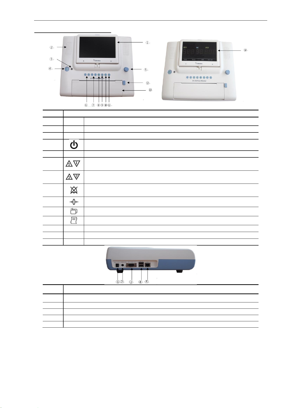
1.3 Product outlook
LCD type
LED type
Figure1-1: Front view
Left side view
Right side view
Figure1-2: Side view
BT-350 Operation Manual
9
1.4 Description of System components
No
Name & Description
①
TFT Color LCD
②
Speaker
③
Power indicating LED (AC: Green / Battery: Orange)
④
Power ON/OFF button: Turns the power On or Off
⑤
Control knob
⑥
DOP1 volume UP/DOWN button: Increase or decrease DOP1 fetal audio volume in
monitoring mode
⑦
DOP2 volume UP/DOWN button: Increase or decrease DOP2 fetal audio volume in
monitoring mode
⑧
Alarm sound ON/OFF button: Makes the alarm sound enable or disable in monitoring
mode
⑨
UC reference button: Resets the UC baseline in monitoring mode
⑩
Mode change button: The monitor operating mode change
⑪
Printer ON/OFF button: Turn the printer On or Off
⑫
Print door open button
⑬
Printer door
⑭
7 segment LED Display(for LED type)
Name & Description
①
Power adaptor jack connector
②
Event marker connector
③
RS-232C port
④
USB port
⑤
LAN port

BT-350 Operation Manual
10
Name & Description
①
DOP1/AST connector
②
DOP2/AST connector
③
UC connector
1.5 Understanding the display
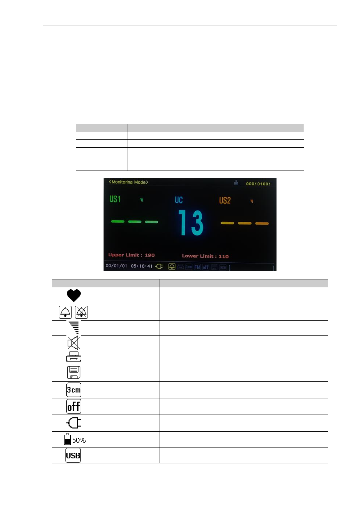
1.5.1Main monitoring screen of LCD display
Figure 1-3 –Main monitoring screen of LCD display –Graph mode
1.5.1.1 Mode frame
The mode frame shows the current mode. There are monitoring mode, setup mode, and trend mode.
1.5.1.2 Patient ID frame
This frame displays patient identification. The monitor encodes the identification using the date to ensure no
duplication of IDs. The user may enter a patient name if desired.
1.5.1.3 FHR graph frame
The FHR graph frame displays a graphical representation of the FHR. The horizontal line is scaled according to the
printer paper setting (Refer to the “Printer paper select” chapter). The graph displays 4 minutes and 30 seconds of
data.
This frame will show two heart rate trends when two ultrasound transducers are connected.
1.5.1.4 FHR numeric frame
The FHR numeric frame displays the fetal heart rate, a heart icon, and the volume icon. The heart rate value displays
the most recently calculated fetal heart rate. When a valid heart rate is detected, the heart icon blinks at the
measured heart rate interval. The volume icon indicates the current speaker volume setting.
When the second ultrasound transducer is connected, the heart rate frame “US2” will display the fetal heart rate, a
heart rate icon, and the volume icon automatically. The trace-offset (DOP2 offset) icon will also appear in the FHR
frame if two ultrasound transducers are connected and ultrasound trace offset (DOP2 offset) has been enabled. The
trace-offset icon is either “[+10]”, “[+20]”, “[+30]”, or “[+40]” depending on the setting.
1.5.1.5 UC (TOCO) graph frame
This frame displays the relative uterine contraction in graph form. The scale is from zero to 100 in relative units. The
graph displays 4 minutes and 30 seconds of data.
1.5.1.6 UC (TOCO) numeric frame
This frame displays the numerical value from the UC probe representing relative uterine contraction. This frame also
shows the present UC baseline value. A user can reset the baseline to 10.
1.5.1.7 Time/Date frame
This frame shows the current time and date and power source. The time and date can be changed. If the device is
operating using AC power then AC power icon is displayed. If the device is operating by battery power, then a battery
icon is displayed. The battery icon also displays charging status. If the battery option is equipped selected, the internal
BT-350 Operation Manual
11
battery is used when AC power disconnected.
The battery icon will flash when the battery is low (less than 10 minutes of remaining operating time). If the battery is
low (Low Battery) the printer will stop operating and the battery icon will turn to red. The AC power should be
connected to the device to charge the battery. The device will operate normally while the AC power is charging the
battery.
1.5.1.8 Status frame
This frame displays alarm status icon, printer status icon, printer speed set value, fetal movement set status, auto
printing status, save icon, and USB icon. The alarm icon is a bell. A diagonal line on the bell indicates that alarm is
disabled.
1.5.1.9 Message frame
This frame displays the error and current operation status. The error message will be displayed when the device is
unable to operate properly. If this error message displayed, stop using the device and check.
Message
Description
DOP1 OPEN
DOP1 is not connected while BT-350 is monitoring
DOP2 OPEN
DOP2 is not connected while BT-350 is monitoring
DOOR OPEN
Printer door is opened while BT-350 is printing
No PAPER
Paper is not loaded while BT-350 is printing
LOW BAT
Battery’s charging level is low while BT-350 is monitoring
Figure 1-4 –Main monitoring screen of LED display –Number mode
Symbol
Name
Description
Heart Rhythm Icon
Blinking according to heart rate
Alarm Sound Icon
Indicating of Alarm sound enable/disable
Volume Icon
Indicating the speaker volume setting for the fetal echo sounds
Mute Icon
In the case of volume level 0
Print Icon
Indicating a printing status
Save Icon
Indicating a data saving status
Print Speed Icon
Indicating print speed status
Auto Print Icon
Indicating of the status of the auto printing function
AC Power Icon
Indicates the unit is operating on AC power
Battery Status Icon
Indicates the battery charge status (Only when the BT-350 is
operated by battery, this icon is displayed.)
USB Icon
Indicating USB connection status.
BT-350 Operation Manual
12
1.5.2 Main monitoring screen of LED display
Figure 1-5 –Main monitoring screen of LED type
1.5.2.1 Heart Rhythm
The heart symbol is turned on according to FHR value. If FHR value is out of normal range (30 ~ 240), the heart symbol
is turned off.
1.5.2.2 FHR/UC frame
The FHR frame displays the detected fetal heart rate. When the second ultrasound transducer is connected, the “US2”
frame will display the fetal heart rate too.
This frame displays the numerical value from the UC probe representing relative uterine contraction. This frame also
shows the present UC baseline value. A user can reset the baseline to 10.
1.5.2.3 Status frame
This frame shows the LED type status.
Display
Description
Print
Indicating a printing status
Alarm
Indicating of Alarm sound enable/disable
USB
Indicating of USB record status
US +20
Indicating of US2 offset enable/disable
2 Operation of LCD type
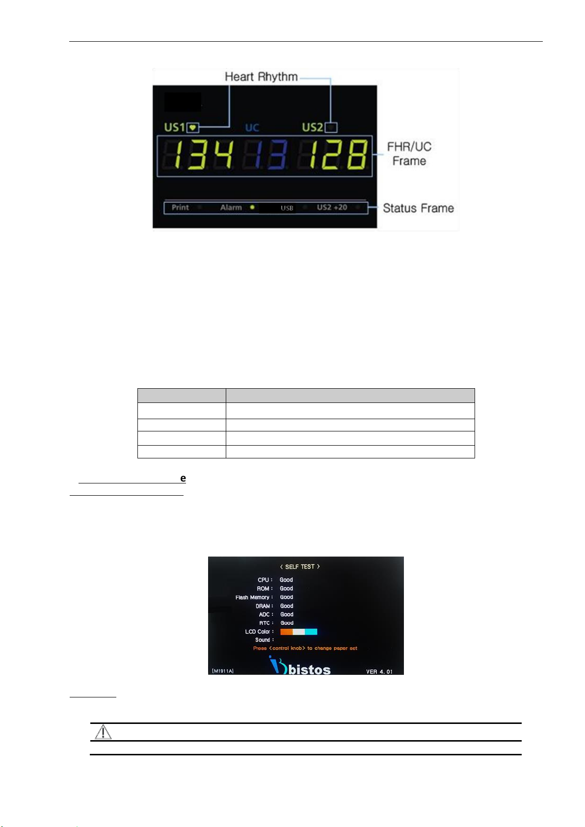
2.1 System startup: Self-test
The monitor performs a self-test each time it is turned on. This process allows the monitor to check various systems
for proper operation. The monitor displays the startup screen during the power-on-self-test. When the test is
successfully completed the BT-350 displays the monitoring screen.
If a malfunction is detected an error message displays and an error tone is sounded. The error tone will continue until
the power is turned off. If this occurs, remove the monitor from use until appropriate action is taken.
Fig. 2.1 Self-test display
2.2 Buttons
There are seven buttons located on the front panel. The buttons are activated by pushing with the finger until an
audible click sound is heard.
CAUTION
Never use sharp or pointed objects to operate the front-panel switches.
BT-350 Operation Manual
13
The operation of the button is as below.
Symbol
Name
Description
Power On/Off Button
Turns the power on or off.
Dop1 Volume Up/Down
Button
Decreases or increases Dop1 fetal audio volume in monitoring
mode.
Dop2 Volume Up/Down
Button
Decreases or increases Dop2 fetal audio volume in monitoring
mode.
Alarm On/Off Button
Makes the alarm sound enable or disable in monitoring mode.
UC Reference Button
Resets the UC baseline in monitoring mode.
Mode Button
Puts the monitor into trend scroll mode. The trend frames
show historical patient data and the control knob provides
navigation capability.
Record On/Off Button
Turns the record on or off.
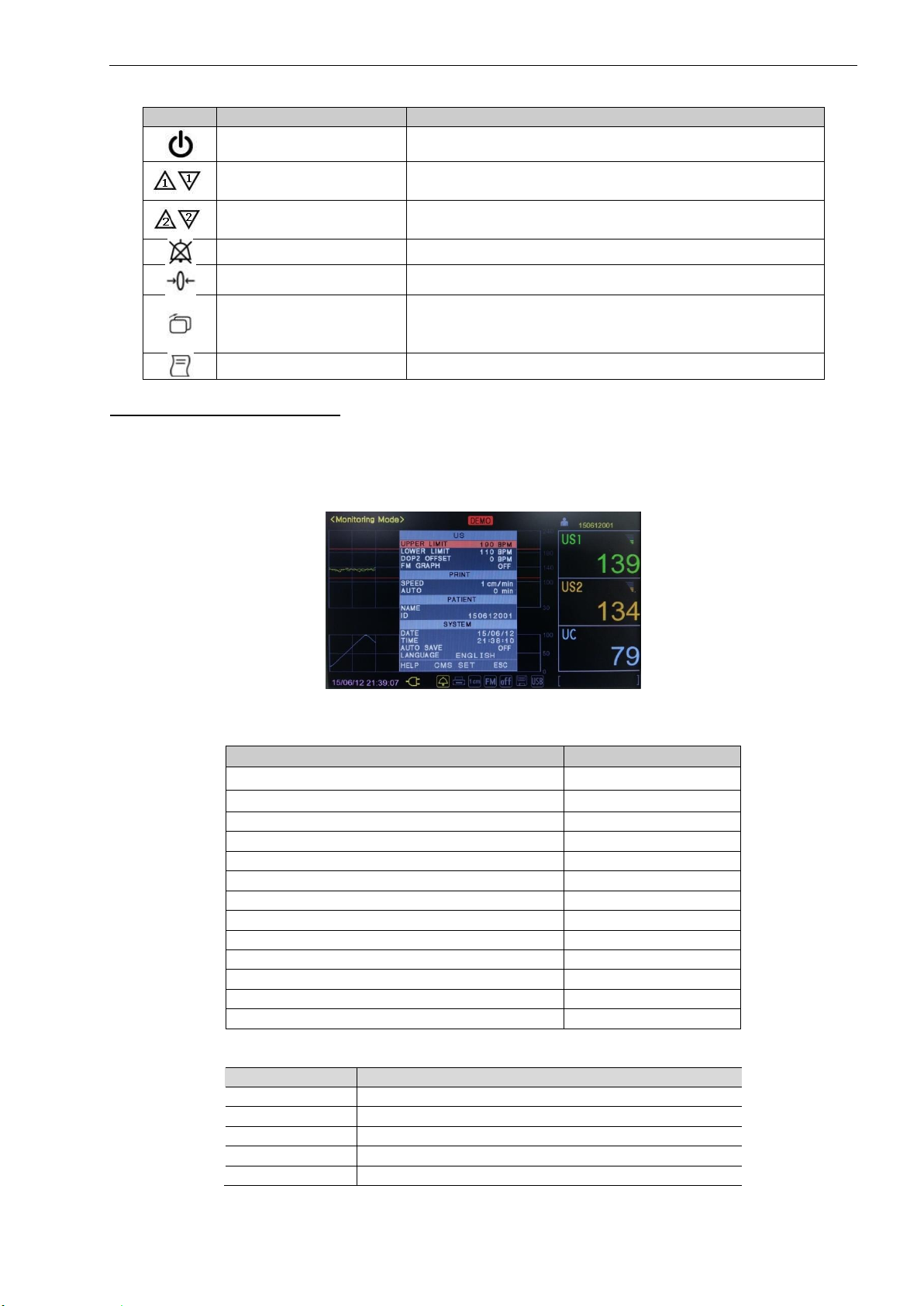
2.3 Control knob and system setting
Use the control knob to select the parameter to change and to adjust the parameter value selected.
Press down the knob activates the setup menu as shown in Fig.2.2. Turn the knob clockwise or counterclockwise to
move the cursor and press down it to select the parameter. Turn the knob to change the value and press down to store
the value. The basic operation sequence is summarized in the below table. Select “ESC” and press down the knob to
save the exit setup menu.
Fig. 2.2 System setup menu
The monitor has several configuration settings that the user can change. These parameters are unaffected when the
monitor is powered down. Below is the default setting value of parameters.
Parameter
Factory Default
Fetal Heart Rate Upper Alarm Limit
190 BPM
Fetal Heart Rate Lower Alarm Limit
110 BPM
Dop2 Trace Separation (Dop2 Offset)
0 BPM
FM Graph
OFF
Printing Speed
3 cm/min
Auto Printing
0 MIN
Patient Name
blank
Patient ID
Date/Sequential number
Date
YY/MM/DD
Time
HH:MM:SS
Auto Save
OFF
Language
English
Paper
FS151-90-80R-01
The basic operation of the control knob to parameter settings is as follows.
Activity
Desired Result
Press down
Enter the setup menu
Rotate
Move the cursor
Press down
Select the parameter to change.
Rotate
Change the value
Press down
Store the new value.
BT-350 Operation Manual
14
2.3.1 Alarm upper limit/lower limit set
The upper and lower alarm limit can be changed. The adjustable range for upper limit is [Lower limit +10] ~ 240 BPM
with 5 BPM step. The adjustable range for a lower limit is 30 ~ [Upper limit –10] BPM with 5 BPM step.
2.3.2 DOP2 offset set
The two waveforms for each Doppler transducer can be separated to prevent some confusing and enable to see the
waveform clearly. When ultrasound trace separation is enabled, the trend data for ultrasound channel 2 is shifted up
by either of 10, 20, 30 or 40 BPM in printing. This feature is useful when both heart rates waveforms are similar. The
heart rate value shown in the numeric frame is not affected. If DOP2 offset is selected, one of [+10], [+20], [+30] or
[+40] is displayed in US2 numeric frame depending on the selection.
2.3.3 Fetal movement (FM) graph
The fetal movement graph display can be turned on and off.
2.3.4 Printing speed
The printing speed can be selected among 1cm/min, 2cm/min, and 3cm/min.
2.3.5 Auto printing
The printer can be turned off automatically. If the value is set to 0, the printer will print out until the paper ended. If
the value is set to 10, the printer will turn off after 10 minutes. You can choose among 0, 10, 20, 30, 40, 50, and 60.
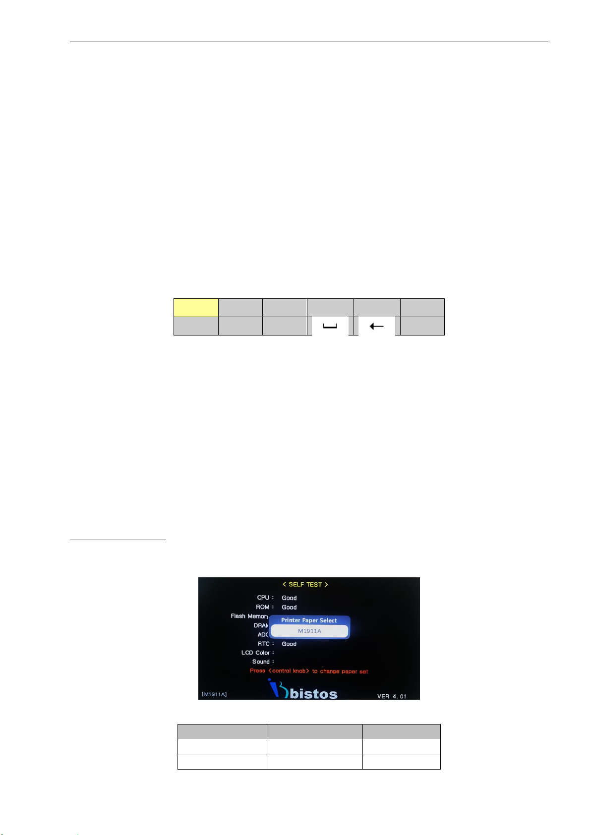
2.3.6 Entering the patient name
You can enter a patient name if required. If you select the [NAME] item, you can see the following display to enter the
name. If you want to enter the second character of the selected character set, you can press down the knob twice. For
example, D requires one press down and F requires three press down.
.QZ
ABC
DEF
GHI
JKL
MNO
PRS
TUV
WXY
ESC
2.3.7 Entering the patient ID
Patient ID is generated automatically when BT-350 has turned on. This ID is composed of YYMMDD + 3 digits serial
number. The 3 digits number can be changed manually.
2.3.8 Set date and time
Set the date and time if required. Enter date in the YY/MM/DD format and time in the 24 hours format.
2.3.9 Set auto save
You can save the measured data manually or automatically. If [AUTO SAVE] function activates, all the measured data is
stored from the power on. The default value for this function is OFF.
2.3.10 Set language
The default language setting is English. You can choose among English, Chinese, Spanish, German, French, Indonesian,
Russian, Portuguese, Turkish, Polish, Italian, Korean, Japanese, and Serbian.
2.3.11 CMS (Central monitoring system) settings
You can change the communication channel, IP address, subnet address, gateway address, port address, and HRV
(Heart Rhythm Variability) sensitivity. You can choose the communication channel between Serial and Ethernet. And
you can choose the HRV sensitivity among low, middle, and high. You can enter a value for other parameters.
2.4 Printer paper select
You can use two different types of paper, FS151-90-80R-01 and M1911A, with BT-350. If you press down the control
knob during the self-test, you can select the printer paper.
Fig. 2.3 Printer paper select
Paper
Graph Display Area
Print Area
FS151-90-80R-01
30-240 bpm
30-240 bpm
M1911A
50-210 bpm
50-210 bpm
BT-350 Operation Manual
15
CAUTION
If you use a different type of paper from the selected paper type, the printed data will be incorrect. Be sure
to check the selected paper type is the same with used paper.
When paper type is changed, the alarm upper limit is changed to 190 and alarm lower limit is changed to
110.
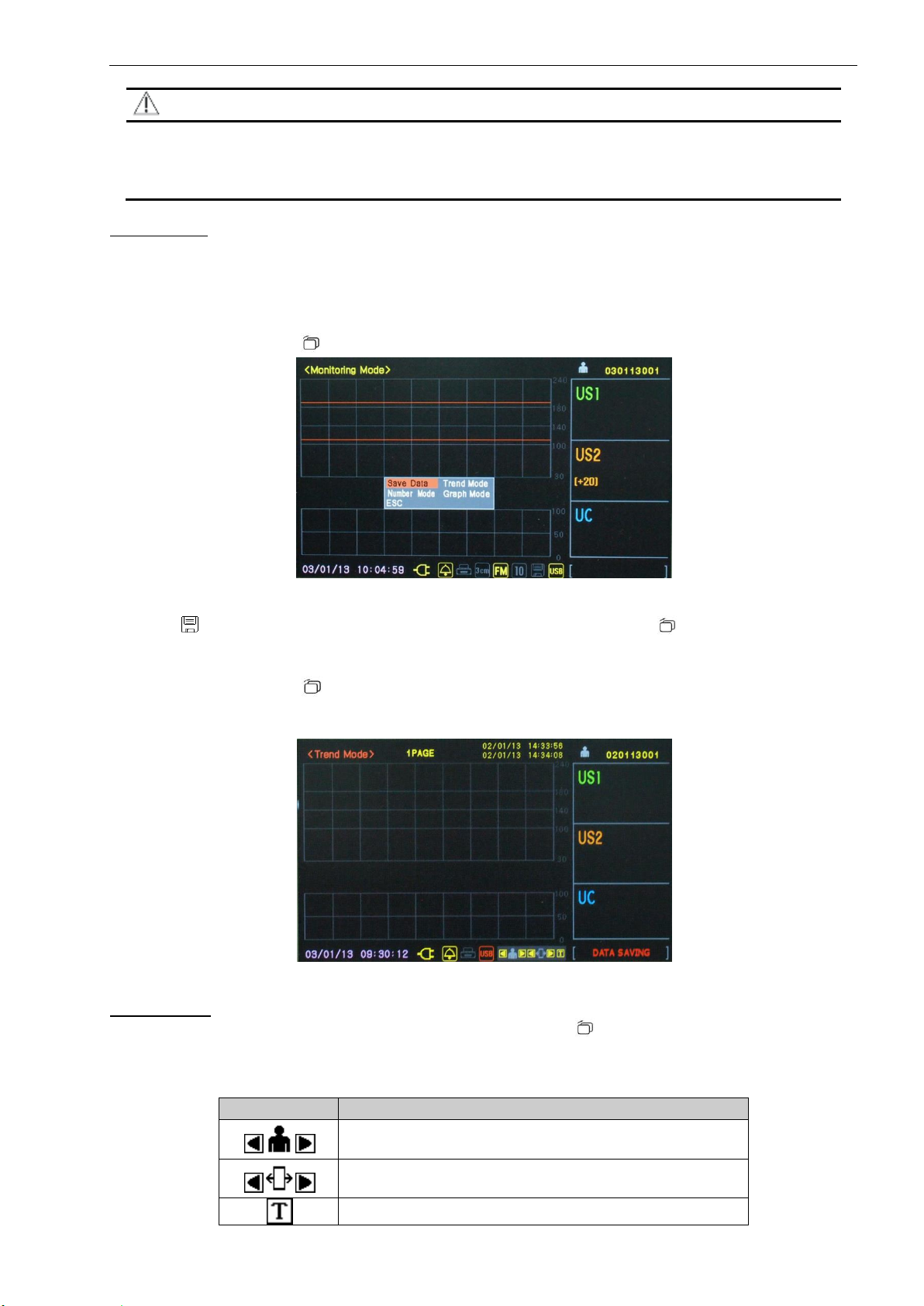
2.5 Data saving
The measured data can be saved to the monitor itself and USB, if connected, at the same time. For each patient, up to
3 hours of data can be saved. Totally 450 hours of data can be saved. The saved data can be totally copied moved from
BT-350 to USB memory later.
2.5.1 How to save data
Press down the mode button [ ] to activate the following menu.
Fig. 2.4 Save Date display
Select [Save Date] item and press down the control knob to start the saving function. If the save function activated
save icon [ ] is activated by yellow color and rotate. Press down the mode button [ ] to finish data saving. If the
USB memory is connected, the USB icon activated by yellow color and data saved to USB memory simultaneously.
2.5.2 How to copy the saved data to USB
Press down the mode button [ ] to activate menu while USB memory has connected. Select “Trend Mode”. Turn the
control knob to select USB and the USB will turn to red color. Then press down the control knob to copy the saved data
to USB memory.
Fig. 2.5 Trend mode display
2.6 Trend mode
In trend mode, you can see the saved data. Press down the mode button [ ] to activate the menu shown in figure 2.4.
Rotate the control knob to select the “Trend Mode”. Press down the control knob to enter the trend mode.
The data saved date and time and the relevant patient ID are displayed. You can search for data by a patient or by page
and tracing saved graphic data.
Button
Function
Searching for saved data by patient ID. Selecting Previous /
Next Patient
Searching for saved data by saved page. Selecting Previous /
Next Page
Tracing the saved graphic data
BT-350 Operation Manual
16
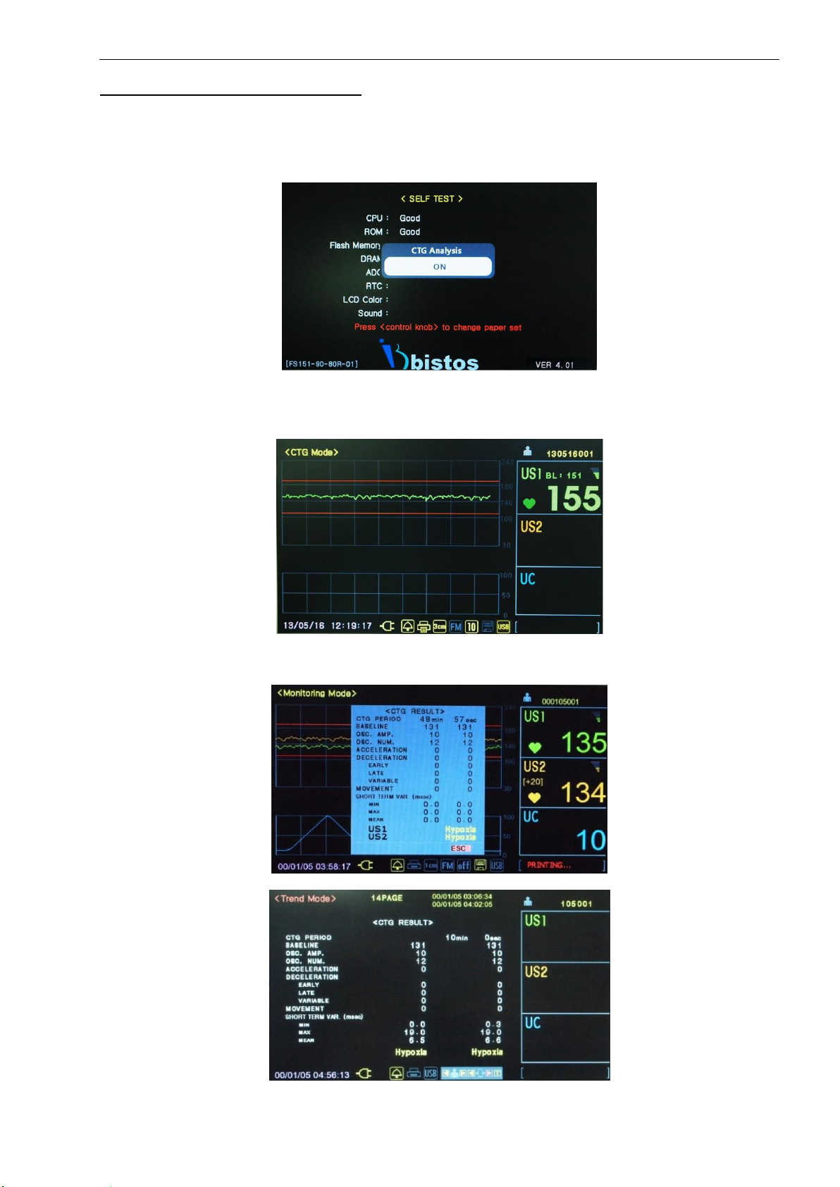
2.7 CTG (Cardiotocography) analysis function
The CTG analysis function is a computerized diagnosis of fetal heart rate and uterine contraction patterns.
When this function is activated, a CTG algorithm monitors continuous FHR and UC value for 20 minutes and analyzes
FHR variability and relative FHR response to UC change.
To activate this function, press down the control knob during self-test for 4 times and then the following menu will be
displayed.
Fig. 2.6 CTG analysis function
After selecting ON the CTG analysis function, you can use this function by pressing the [Print] button in the monitoring
mode. On pressing the [Print] button, the mode will change from <Monitoring Mode> to <CTG Mode> and the printing
will be started. On the FHR frame, the <Baseline Value> will be displayed.
Fig. 2.7 CTG mode
When you press down the [Print] button again after more than 20 minutes elapsed, printing will be stopped and CTG
analysis will be ended. The analysis result will be displayed and printed.
Fig. 2.8 CTG results in monitoring mode
Fig. 2.9 CTG result in trend mode

BT-350 Operation Manual
17
2.8 CCV (Cross-channel verification) function
When monitoring two fetuses with two Doppler probes, CCV function will compare the values from both probes and
alerts when the values could be the same source (fetus).
If the difference between two probe values is within 2 bpm for more than 25 seconds during 30 seconds monitoring
period, CCV alert will be generated and icon will be displayed.
To activate this function, press down the control knob during self-test for 3 times and then the following menu will be
displayed.
Fig. 2.10 CCV function
Fig. 2.11 CCV displayed
If the CCV appears during printing the data, icon will be printed on the paper.
Fig. 2.12 CCV printed
3 Operation of LED type
3.1 Buttons
There are seven buttons located on the front panel. The buttons are activated by pushing with the finger until an
audible click sound is heard.
CAUTION
Never use sharp or pointed objects to operate the front-panel switches.
The operation of the button is as below.
Symbol
Name
Description
Power On/Off Button
Turns the power on or off.
Dop1 Volume Up/Down Button
Decreases or increases Dop1 fetal audio volume in
monitoring mode.

BT-350 Operation Manual
18
Symbol
Name
Description
Dop2 Volume Up/Down Button
Decreases or increases Dop2 fetal audio volume in
monitoring mode.
Alarm On/Off Button
Makes the alarm sound enable or disable in monitoring
mode.
UC Reference Button
Resets the UC baseline in monitoring mode.
Mode Button
Puts the monitor into trend scroll mode. The trend frames
show historical patient data and the control knob provides
navigation capability.
Record On/Off Button
Turns the record on or off.
3.2 Information messages
The following messages are displayed to indicate the error and current operation status. The error message is
displayed when the monitor is unable to operate properly. If the error message is showing up, stop using LED type and
take appropriate action.
Message
Description
DOP1 OPEN. Doppler probe is not connected to DOP1
connector
DOP2 OPEN. Doppler probe is not connected to DOP2
connector.
DOOR OPEN. The print door is opened.
NO PAPER. Paper is not loaded
LOW BATTERY. Battery charging level is low
3.3 Control knob and system setting
Use the control knob to select the parameter to change and to adjust the parameter value selected.
The monitor has several configuration settings that the user can change. These parameters are unaffected when the
monitor is powered down. Below is the default set of parameters.
Parameter
Factory Default
Fetal Heart Rate Upper Alarm Limit
190 BPM
Fetal Heart Rate Lower Alarm Limit
110 BPM
Dop2 Trace Separation (Dop2 Offset)
0 BPM
FM Graph
OFF
Printing Speed
3 cm/min
Auto Printing
0 MIN
Paper
FS151-90-80R-01
The basic operation of the control knob to parameter settings is as follows.
Activity
Desired Result
Press down
Enter the setup menu
Rotate
Move the cursor
Press down
Select the parameter to change.
Rotate
Change the value
Press down
Store the new value.
BT-350 Operation Manual
19
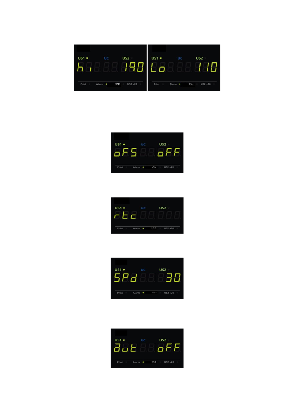
3.3.1 Alarm upper limit/lower limit set
The upper and lower alarm limit can be changed. The adjustable range for upper limit is [Lower limit +10] ~ 240 BPM
with 5 BPM step. The adjustable range for a lower limit is 30 ~ [Upper limit –10] BPM with 5 BPM step.
Fig. 3.1 Alarm Upper /Lower Limit
3.3.2 DOP2 offset set
The two waveforms for each Doppler transducer can be separated to prevent some confusing and enable to see the
waveform clearly. When ultrasound trace separation is enabled, the trend data for ultrasound channel 2 is shifted up
by either of 10, 20, 30 or 40 BPM in printing. This feature is useful when both heart rates waveforms are similar. The
heart rate value shown in the numeric frame is not affected. If DOP2 offset is selected, one of [+10], [+20], [+30] or
[+40] is displayed in US2 numeric frame depending on the selection.
Fig. 3.2 DOP2 offset
3.3.3 Set date and time
Set the date and time if required. Enter date in the YY/MM/DD format and time in the 24 hours format.
Fig. 3.3 Date and time
3.3.4 Printing speed
The printing speed can be selected among 1cm/min, 2cm/min, and 3cm/min.
Fig. 3.4 Printing speed
3.3.5 Auto printing
The printer can be turned off automatically. If the value is set to 0, the printer will print out until the paper ended. If
the value is set to 10, the printer will turn off after 10 minutes. You can choose among off, 10, 20, 30, 40, 50, and 60.
Fig. 3.5 auto printing
Other manuals for BT-350
1
Table of contents
Other Bistos Medical Equipment manuals

Bistos
Bistos BT-450 User manual

Bistos
Bistos BT-700 User manual

Bistos
Bistos BT-250 User manual

Bistos
Bistos BT-720 User manual

Bistos
Bistos BT-710 User manual

Bistos
Bistos BT-220 User manual

Bistos
Bistos BT-400 User manual

Bistos
Bistos BT-770 User manual

Bistos
Bistos BT-500 User manual

Bistos
Bistos BT-200 User manual


Popular Medical Equipment manuals by other brands


Getinge
Getinge Arjohuntleigh Nimbus 3 Professional Instructions for use

Mettler Electronics
Mettler Electronics Sonicator 730 Maintenance manual

Pressalit Care
Pressalit Care R1100 Mounting instruction

Denas MS
Denas MS DENAS-T operating manual

bort medical
bort medical ActiveColor quick guide

AccuVein
AccuVein AV400 user manual


