Black Box LB320A User manual
Other Black Box Extender manuals
Black Box
Black Box VX-HDMI-POE-MTX User manual
Black Box
Black Box Sync SHM-NPR MP User manual
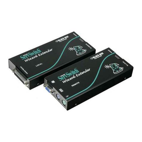
Black Box
Black Box ServSwitch ACU5010A User manual

Black Box
Black Box IC408A User manual
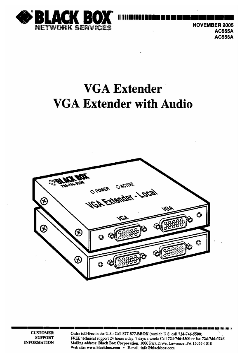
Black Box
Black Box AC555A User manual
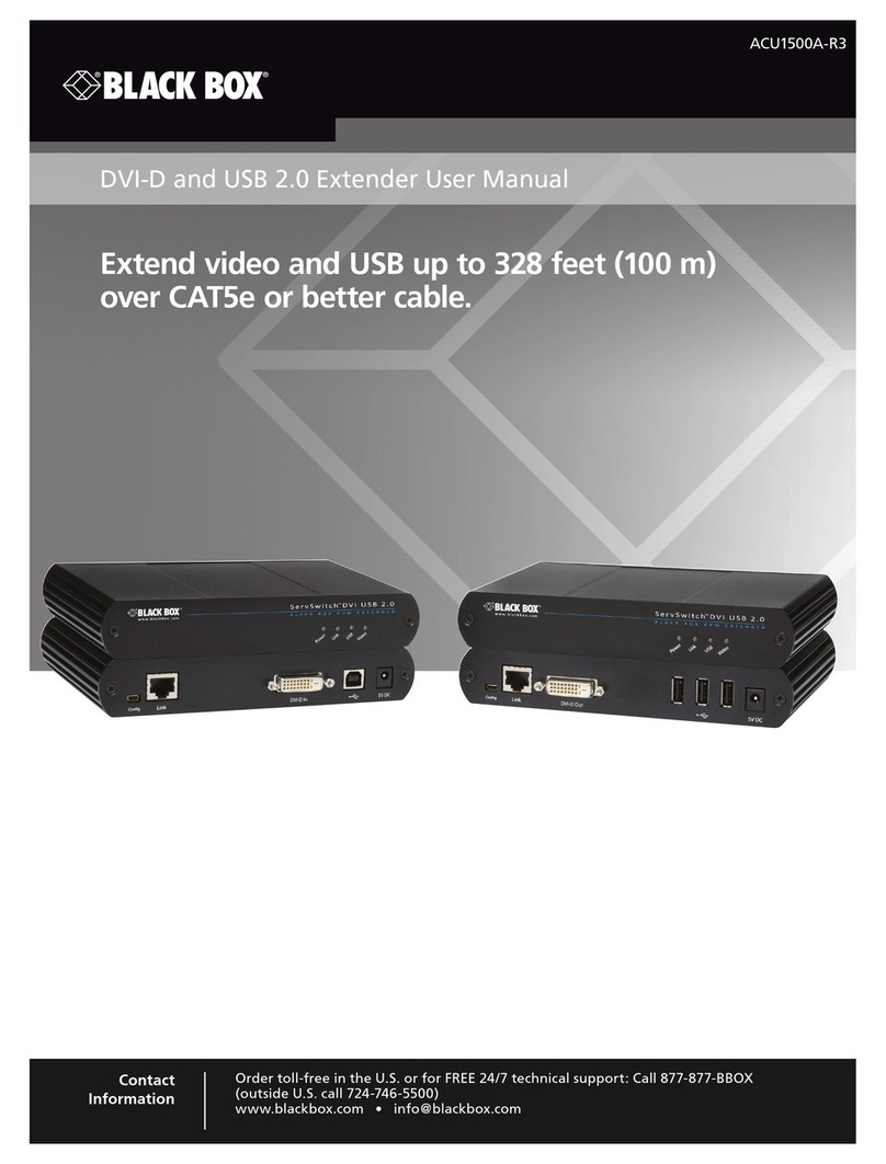
Black Box
Black Box ACU1500A-R3 User manual

Black Box
Black Box IC169A User manual
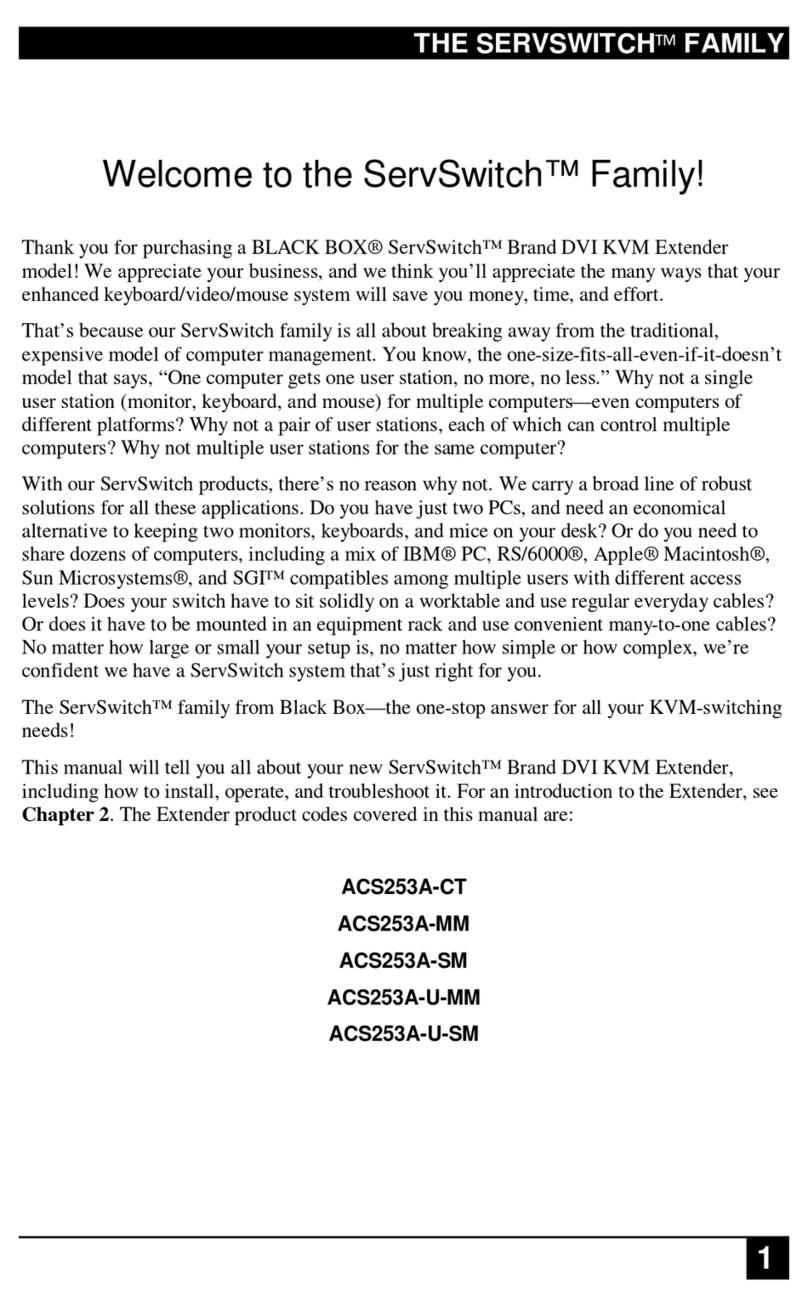
Black Box
Black Box ACS253A-CT User manual
Black Box
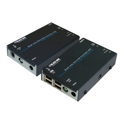
Black Box Abeo G.703 LAN Installation and operating instructions
Black Box
Black Box ACU5520A User manual
Black Box
Black Box ACS253A-U-MM User manual

Black Box
Black Box ACU8000A User manual

Black Box
Black Box EMERALD PE SH User manual
Black Box
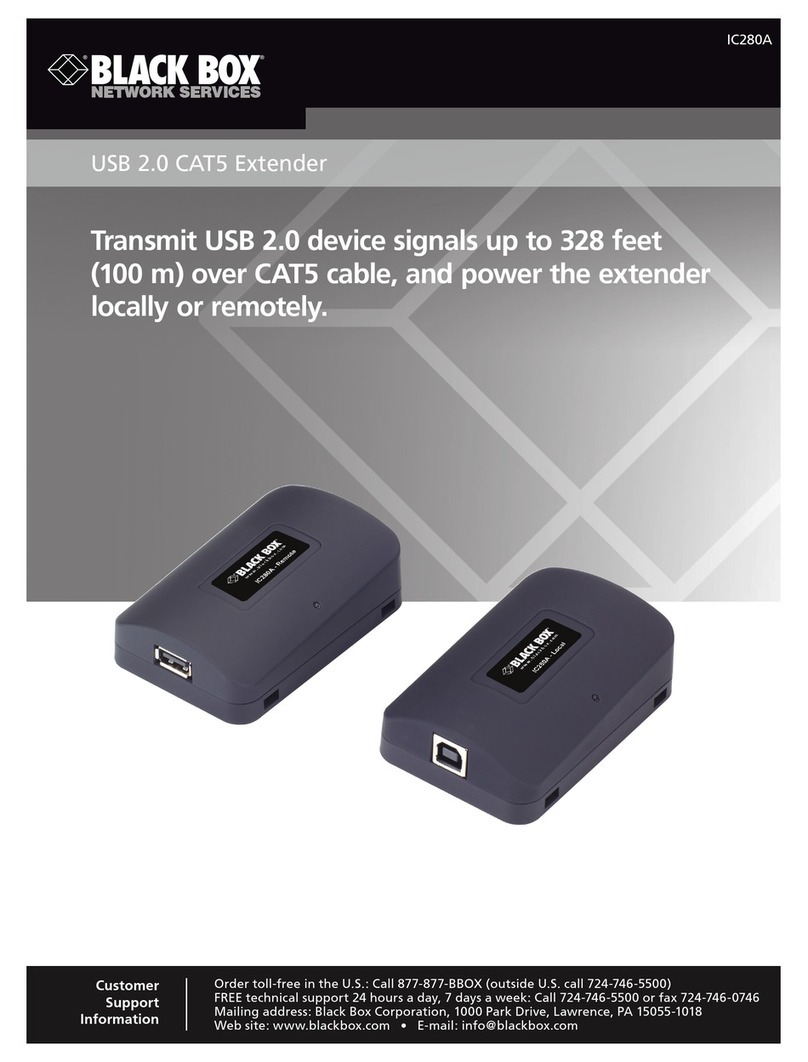
Black Box IC280A User manual

Black Box
Black Box LB200A User manual
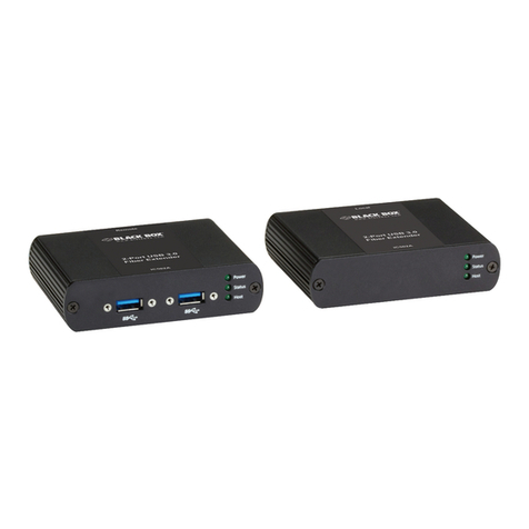
Black Box
Black Box ICS02A User manual

Black Box
Black Box ServSwitch ACU1022A User manual

Black Box
Black Box LWE121A User manual
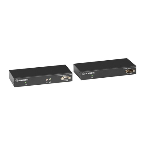
Black Box
Black Box KVX Series Instructions for use
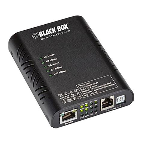
Black Box
Black Box LB300A-RACK User manual
Popular Extender manuals by other brands

foxunhd
foxunhd SX-AEX01 operating instructions

TERK Technologies
TERK Technologies LFIRX2 owner's manual

Devolo
Devolo Audio Extender supplementary guide

Edimax
Edimax EW-7438RPn V2 instructions

Shinybow USA
Shinybow USA SB-6335T5 instruction manual

SECO-LARM
SECO-LARM ENFORCER EVT-PB1-V1TGQ installation manual

