Bodyworx E400 User manual

BODYWORX
BODY WORX
Version A
Retain this owner’s manual for future reference
Read and follow all instructions in this owner’s manual
ELLIPTICAL
Model No:
E400

Step 1
Visit our Website
Go to the GPI Sports website: www.gpisports.com.au/warranty
Warranty Registration Form
Step 2
Enter Purchase Information
Enter all purchase information including the serial number and proof
of purchase which can be uploaded from this page
Step 3
Call Our Toll Free Number
If a warranty service request is required on your product
please call the toll free number - 1800 005 770
Congratulations on purchasing your product, we at GPI believe that our product range is of the
highest quality and represents great value for money.
We back our product range up with our industry leading warranty.
Please see below for the step by step instructions on how to register your product warranty
online.
GPI Sports & Fitness

Safety Instructions
•Toensure the best safety of the exerciser, regularly check it on damages and worn parts.
•If you pass on this exerciser to another person or if you allow another person to use it, make sure that that person is familiar with
the content and instructions inthese instructions.
•Only one person should use the exerciser at a time.
•Before the first use and regularly makesure that all screws, bolts and other jointsare properly tightened and firmly seated.
•Before you start your work-out, remove all sharp-edged objects around the exerciser.
•Only use the exercise for your work-out if it works flawlessly.
•Any broken, worn or defective part must immediately be replaced and/or the exerciser must no longer be used until it has been
properly maintained and repaired.
•Parents and other supervisory persons should be aware of their responsibility,due to situations which may arise for which the
exerciser has not been designed and which may occur due to children’s natural play instinct and interest in experimenting.
•If you do allow children to use this exerciser, be sure to take into consideration and assess their mental and physical condition
and development, and above all their temperament. Children should use the exerciser only under adult supervision and be
instructed on the correct and proper use of the exerciser. The exerciser is not a toy.
•Make sure there is sufficient free space around the exerciser when you set it up.
•Toavoid possible accidents, do not allow children to approach the exerciser without supervision, since they may use it in a way
for which it is not intended due to their natural play instinct and interest in experimenting.
•Please note that an improper and excessive work-out may be harmful to your health.
•Please note that levers and other adjustment mechanisms are not projecting into the area of movement during the work-out.
•When setting upthe exerciser, please make sure that the exerciser is standing in a stable way and that any possible unevenness
of the floor is evened out.
•Always wear appropriate clothing and shoes which are suitable for your work-out on the exerciser. The clothes must be designed
in a way so that they will not get caught in any part of the exerciser during the work-out due to their form (for example, length). Be
sure to wear appropriate shoes which are suitable for the work-out, firmly support the feet and which are provided with a non-slip
sole.
•Be sure to consult a physician before you start any exercise program. He may give you proper hints and advice with respect to
the individual intensity of stress for your work-out and sensible eating habits.
•Be sure to set up the exerciser in a dry and even place and always protect it from humidity. If you wish to protect the place
particularly against pressure points, contamination, etc., it is recommended to put a suitable, non-slip mat under the exercise
•The general ruleis that exercisers and training devices are no toys. Therefore, they must only be usedbyproperly informed or
instructed persons.
•Stop your work-out immediately incase of dizziness, nausea, chest pain or anyother physical symptoms. In case of doubt,
consult your physician immediately.
•Children, disabled and handicapped persons should use the exercise onlyunder supervision and in presence of another person
who may give support and useful instructions.
•Be sure that your body parts and those of other persons are never close to any moving parts of the exerciser during its use.
•When adjusting the adjustable parts, make sure they are adjusted properly and note the marked, maximum adjusting position, for
example of the saddle support, respectively.
•Do not work out immediately after meals!
•Maximum User Weight is 135 KG (297 LBS)
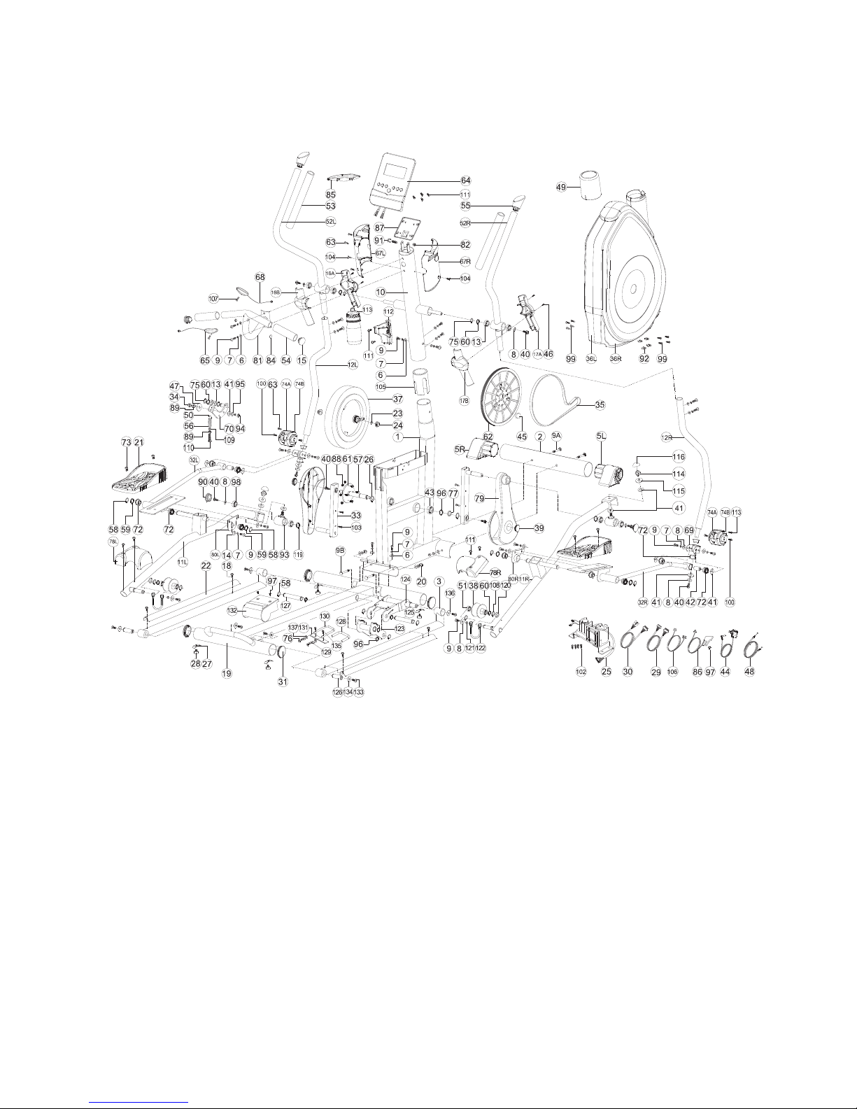
Exploded drawing:

Checking list:

Part list:
Part No. Description QTY Part No. Description QTY
1tekcarbretupmoctfeLL761emarfniaM1
1tekcarbretupmocthgiRR761rezilibatstnorF2
2elbaceslupeldnaH862maebgnidilS3
2tnioJ961pactooftfeLL5
1leehweldirofetalpgnixiF071pactoofthgiRR5
41gnihsuB2761T5.1x5.8Dx22DrehsawdevruC6
4L51*1*6MtloB3742T2x2.8Dx4.51DrehsawgnirpS7
8 Flat washer D25*D8.5*2T 10 74A Left cover for universal joint 2
9 Allen bolt M8x1.25x20L 22 74B Right cover for universal joint 2
4)T1(61-Spilc-C572L09x52.1x8MtlobkcenerauqSA9
9B Square neck bolt M8*1.25*80L 2 76 Taper washer D14*D8.5*4T 2
1T5.1*12D*62DrehsawtalF771tsoprabeldnaH01
1leehwrofrevoctfeLL871ladeptfelrofebutgnitroppuSL11
11R Supporting tube for right pedal 1 78R Right cover for wheel 1
12L Supporting tube for left movable
handlebar
2knarcrofrevoC971
12R Supporting tube for right movable
handlebar
1 80L Enforcing plate for left footboard 1
1draobtoofthgirrofetalpgnicrofnER086ZZ20599#gniraeB31
1rabeldnaH184T2.1x5.8Dx61DrehsawtalF41
15 Mushroom cap D11/4’’*29L 2 82 Nylon nut M8*1.25*8T 1
2)T1(51-Spilc-C381rabeldnahtfelrofrevoCtnorFA61
2gulpelbaC481rabeldnahtfelrofrevoCraeRB61
1tlebtsehC581rabeldnahthgirrofrevoctnorFA71
1elbacrosneS681rabeldnahthgirrofrevoCraeRB71
1retupmocroftekcarbgnixiF786L51*1*6Mtlob81
4T6x0.1x6MtunnolyN881rezilibatsraeR91
2T6*52.1*8MtuN984L51*52.1*8MtundemoD02
2revoelxa092ladeP12
1L54*52.1*8MtlobnellA192rediugmaebgnidilS22
37.7*5.62*6DniP291T2*01D*22DrehsawtalF32
24 Anti-loosen nut 3/8"-26 2elxagnilloR392T5.6xFNU
1L03x52.1x8MtlobnellA491rotoM52
26 C-clip D22.5*D18.5*1.2T 2 95 Flat washer D30*D8.5*2.0T 1
5T5.0*3.02D*72DrehsawdevaW694teehskcoL72
3L21*8.0*5MtloB794leehwdnuorelbatsujdA82
4ZZ3006#gniraeB891elbacretupmocreppU92
01L02x4.1x2.4TSwercS991elbacretupmocrewoL03
4L51*8.0*5MtloB0014pacdnuoR13
4L51x4.1x2.4TSwercS2011ladeptfelroftekcarBL23
4L02*14.1*4TSwercS3011ladepthgirroftekcarBR23
2L51*14.1*4TSwercS4012knarC33
1ebutrennI5011T8*52.1*8MtunnolyN43
1elbaccirtcelE6011tlebevoorg-itluM53
2L52x14.1x4TSwercS7011revocniahctfeLL63
2)T1(71-Spilc-C8011revocniahcthgiRR63
1L31*51DtungnixiF9011leehwylF73
1L05x52.1x8MtlobnellA0112leehW83
01L51*8.0*5MtloB1112revocediS93
1redlohelttoB211852x52.1x8MtloB04
1elttoB31111T4.0*42D*01DrehsawtalfcitsalP14
2T01*5.1*01MtunnolyN4112elxA24
2T3*5.01D*83DrehsawtalF5112ZZ4006#gniraeB34
2pacwercS6111rotpadA44
2T3.0*22D*71DrehsawdevaW9111tengamdnuoR54
talF0214L51*0.1*5.3TSwercS64 washer D23*D17.2*1.5T 2
47 Plastic flat washer D50*D10*1.0T 1 121 Spacer D11.5*D8*3.5T 2
2Cable for wheel2211elbacnoisneT84
1elxagnilloR3211revoctsoprabeldnaH94
1elopgnitsujdA4211paccitsalP05
1noituloverfoelxA5214ZZ2006gniraeB15
52L Left movable handlebar 1 126 Fixing axle D23.6*56L 2
1ladeptnorffoelxA7211rabeldnahelbavomthgiRR25
1pirGdnaH8212L077*T3*62DmaoF35
2L5.02*5.01D*1DgnirpS9212L521xT4x03DmaoF45
1eldnahgniyrrac0312pacdnuoR55
1teehskcol1311L76*91D*3DgnirpS65
1csiddetulfrofrevocgnitcetorP2314L51x0.1x6MtloB75
58 C-clip D21.5xD17.5x1.2T 10 133 Allen bolt M8x1.25x20L 4
59 Waved washer D26*D19.5*0.3T 4 134 Flat washer D30*D8.5*2T 4
60 Waved washer D21*D16.2*0.3T 5 135 Screw M4x0.7x12L 2

Part No. Description I'd Part No. Description I'd
61 Crank axle 1 136 Flat washer D28xD6.5x2.0T 2
62 Belt 1 137 Flat washer D18*D8.5*1.2T 2
63 Screw ST4*1.41*15L 5 138 Allen spanner 1
64 Computer 1 139 Spanner 1
65 Handle pulse 2
Assembly drawing:
Step 1
1) Assemble the Lock sheet(27)and Adjustable round wheel(28)to the rear stabilizer(19).
2) Assemble the rear stabilizer (19) to the frame (1) by the Allen bolt (9), square neck bolt (9B), the curved washer (6), the
spring washer (7) and the domed nut (20).
3) Fix the rear stabilizer (19) to the frame (1) by the Allen bolt (9B), the curved washer (6) and the spring washer (7).
4) Assemble the front stabilizer (2) to the main frame (1) by the square neck bolt (9A), the curved washer (6), the spring
washer (7) and the domed nut (20).

Step 2
1) Assemble the supporting tube for pedal (11L&11R) to the rolling axle by the screw cap (116), Nylon nut (114), Flat
washer(115)and the plastic flat washer (41) shown as fig.2-1.
2) Assemble the pedal (21) to the supporting tube for pedal (11L&11R) by the bolt (73) shown as fig.2-2.
)3 Using the cable for wheel (122) to let the wheel (38) tied onto the sliding beam from rear stabilizer (19) shown as
fig.2-3. Please follow the assembly instruction as the fig shown.
.4-2.gifsanwohs)121(recapseht,)8(rehsawtalfeht,)9(tlobnellAehtyb)221(leehwrofelbacehtgnixiF)4
5) Assemble the cover for wheel (78L&78R) to the supporting tube for pedal (11L&11R) by the bolt (111) shown as fig. 2-5.

Step 3
1) Assemble the handlebar post cover (49) to the handlebar post (10).
2) Connect the upper computer cable (29) and the lower computer cable (30) shown as fig.3-1.
3) Assemble the handlebar post (10) to the main frame (1) by the curved washer (6), the spring washer (7), and the Allen bolt
(9).

Step 4
1) Assemble the movable handlebar (52L&52R) to handlebar post (10)by the flat washer (8), the waved washer (60) and the
bolt (40) shown as fig. 4-1 and 4-2.
2) Assemble the Handlebar (81) to handlebar post(10) by Allen bolt(9),spring washer(7) and curved washer(6) shown as fig.
4-3. Please pull the handle pulse cable out of the handlebar post as fig shown.

Step 5
1) Assemble the right supporting tube for movable handlebar (12R) to the right bracket for pedal (32R) by the waved washer
(59), the flat washer (8) ,the plastic washer (41) and the bolt (40).Then assemble the cover for universal joint (74A&74B) to
the right bracket for pedal (32R) by the screw (63) and the bolt (100) shown as fig.5-1.
2) Assemble the right supporting tube for movable handlebar (12R) to the right movable handlebar (52R) by the curved
washer (6), the spring washer (7) and the Allen bolt (9) shown as fig. 5-2 and 5-2
3) Assemble the left supporting tube for movable handlebar (12L) to the right bracket for pedal (32L) by the waved washer
(59), the flat washer (8) ,the plastic washer (41) and the bolt (40).Then assemble the cover for universal joint (74A&74B) to
the left bracket for pedal (32L) by the screw (63) and the bolt (100) shown as fig.5-3.
4) Assemble the left supporting tube for movable handlebar (12L) to the left movable handlebar (52L) by the curved washer
(6), the spring washer (7) and theAllen bolt (9) shown as fig. 5-2 and 5-4

Step 6
1) Assemble the bottle holder (112) to the handlebar post (10) by bolt (111). Insert the bottle (113) into the bottle holder.
2) Assemble the cover (16A&16B) for left handlebar to the movable handlebar (52L) by the screw (46) shown as fig. 6-1.
3) Assemble the cover(17A&17B) for right handlebar to the movable handlebar (52R) by the screw (46) shown as fig. 6-2
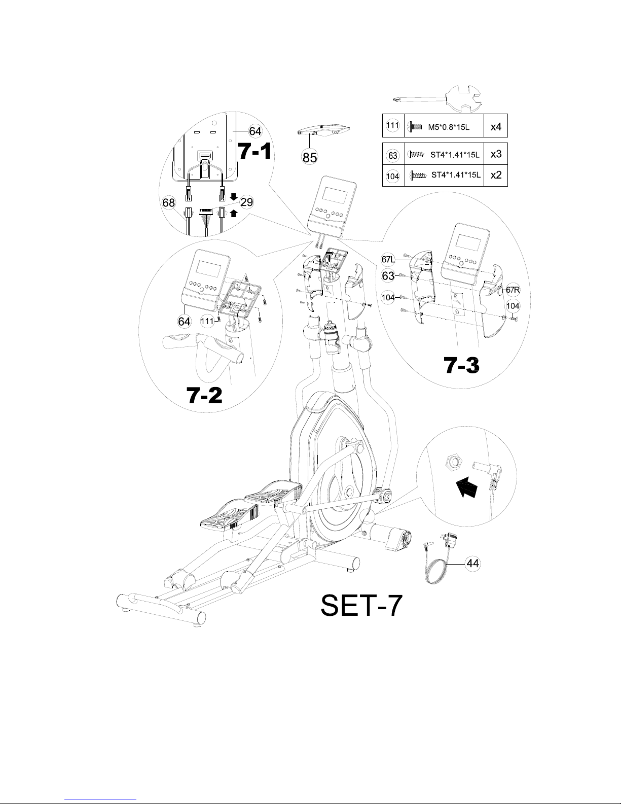
Step 7
1) Connect the upper computer cable (29) and the handle pulse cable (68) to the computer (64) shown as fig7-1.
2) Assemble the computer (64) to the handlebar post (10) by bolt (111) shown as fig 7-2.
3) Assemble the left computer bracket (67L) and the right computer bracket (67R) to the handlebar post (10) by the screw (63)
and the screw (104).
4) Assemble the adaptor (44) and turn on the computer.

INCLINE FUNCTION OPERATION
INCLINE---UP


INCLINE---DOWN


Computer Operation Instructions
SM-2780-31
BUTTON FUNCTION:
MODE/ENTER : In stop mode, the mode is to confirm all exercise data setting, and enter into
program.
RESET : In stop mode, press the button back to main menu.
START/STOP : To start or stop exercise.
RECOVERY : To test hear rate recovery status.
UP : To select training mode and adjust function value up.
DOWN : To select training mode and adjust function value down.
BODY FAT : For body fat measurement
DISPLAY EXERCISE DATA:
TIME : Display range 0:00~99:99 ; Setting range 0:00~99:00
DISTANCE : Display range 0.00~99.99 ; Setting range 0.00~99.90km
CALORIES : Display range 0~9999 ; Setting range 0.00~9990
PULSE : Display range P-30~240 ; Setting range 0-30~240
WATT : Display range 0~999 ; Setting range 10~350
SPEED : 0~99.9km
RPM : 0~999
OPERATION PROCEDURE
1. Connect power supply and computer will power on with a long beep sound, LCD display all segments (drawing A) for 2
seconds and enter into personal data setting mode (gender, age, height and weight) for U1~U4. (drawing B~C)
2. After user data set up, computer will display main menu (drawing D).

Drawing A Drawing B
Drawing C Drawing D
3. In main menu, first exercise program MANUAL will flash, user may press UP and DOWN button to select MANUAL
PROGRAM (12 profiles) (drawing E)PROGRAMUSER PROGRAMHRCWATT.
Drawing E Drawing F
4. Quick Start and Manual :
Before exercise in Manual mode, user my set up TIME, DISTANCE, CALORIES and PULSE target.
After power on, user may press START/STOP button to start exercise in MANUAL immediately without any setting.
Level can be adjusted during exercise by press UP or DOWN.
5. PROGRAM :
Before exercise in Program mode, user may set up TIME target.
Press UP and DOWN to select Program with 12 profiles and press ENTER/MODE to confirm. Level can be adjusted during
exercise by press UP or DOWN.
6. H.R.C. :
Before exercise, computer will ask for user AGE first to calculate TARGET pulse. User may still press UP and DOWN to
change target pulse from 30 to 240.
7. USER PROGRAM :
User may press UP, DOWN and then press MODE to create his own profile. (from column 1 to column 20) User may hold
on pressing MODE button for 2 seconds to quit profile setting.
8. WATT :
The preset watt value 120 is flashing on screen in WATT setting mode. User may use UP, DOWN button to set target
value from 10 to 350. Press MODE button for confirm.

NOTE:
1. This computer require 9V, 0.5mA adaptor.
2. When user stop pedaling for 4 minutes, computer will enter into power save mode, all setting and exercise data will stored
until user start exercise again.
3. When computer act abnormal, please plug out the adaptor and plug in again.
Brick area display total 8 rolls and every profile are composing of 20 rolls.
While exercise, profile display shall rolling for every rolls until user finish
exercise for it selected profile.
Alpha-numeric display user’s selected program name (Manual→Program→User→
HRC→WATT) to remind user he/she is under which workout program.
Table of contents
Other Bodyworx Elliptical Trainer manuals

Bodyworx
Bodyworx EX8 User manual

Bodyworx
Bodyworx E711 User manual

Bodyworx
Bodyworx E738 User manual

Bodyworx
Bodyworx EX7 User manual

Bodyworx
Bodyworx MULTI GYM LX7000HG User manual

Bodyworx
Bodyworx EXT600 User manual

Bodyworx
Bodyworx EXT200 User manual

Bodyworx
Bodyworx E709 User manual

Bodyworx
Bodyworx A732 User manual

Bodyworx
Bodyworx EX900 User manual

Bodyworx
Bodyworx Avalanche User manual

Bodyworx
Bodyworx EFX650 User manual

Bodyworx
Bodyworx E750 User manual

Bodyworx
Bodyworx E1000 User manual

Bodyworx
Bodyworx E708 Premier Series Operation and maintenance manual

Bodyworx
Bodyworx E2000 User manual

Bodyworx
Bodyworx E816 User manual

Bodyworx
Bodyworx E890 User manual


