manuals.online logo
Brands
  1. Home
  2. •
  3. Brands
  4. •
  5. Bosch
  6. •
  7. Control Panel
  8. •
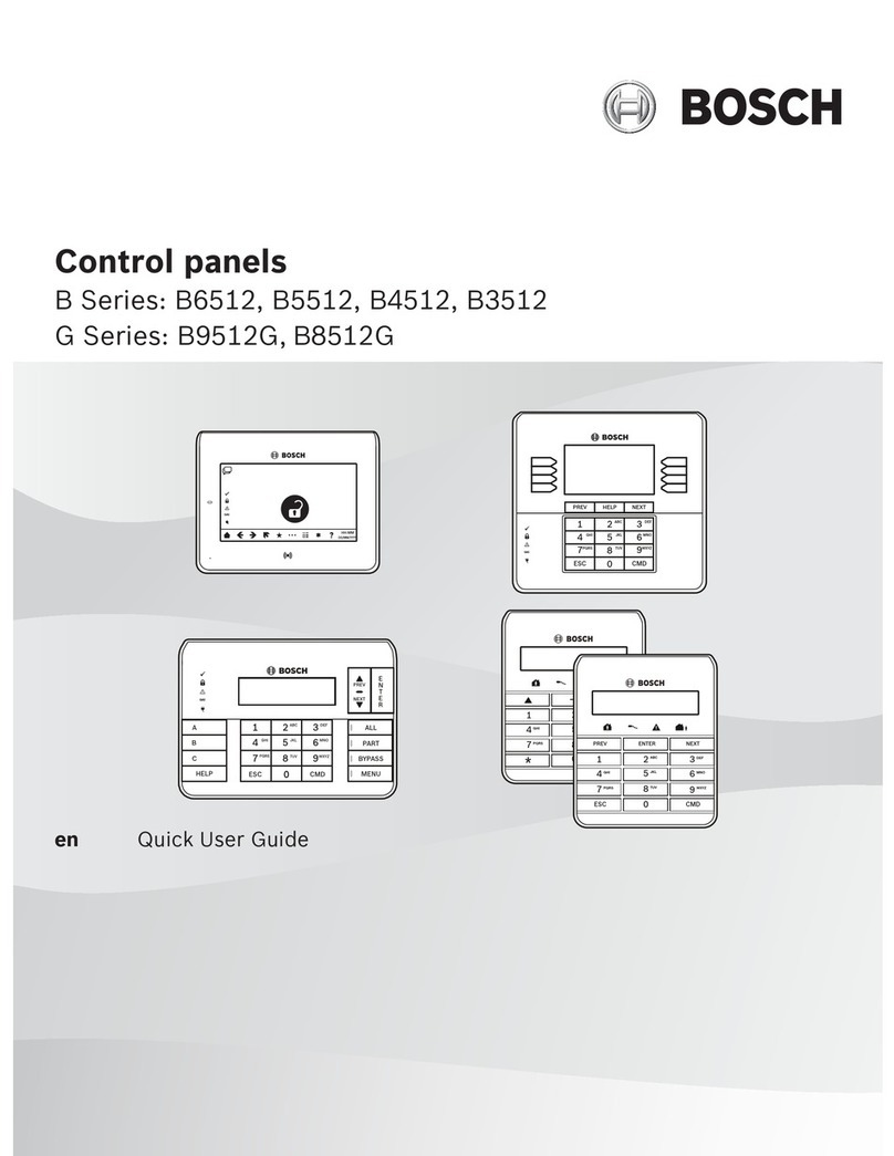
  9. Bosch B5512 User manual

Bosch B5512 User manual

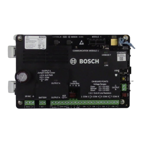
SLOT
SLOT 2
Open 3.7 - 5.0 VDC
Normal 2.0 - 3.0 VDC
Short 0.0 - 1.3 VDC
ETHERNET
100 BASE-T
LINK
USB
COMMUNICATION MODULE 1
C
OUTPUT
B
SDI2
Device Bus
R Y G B
ON-BOARD POINTS
1 COM 2 3 COM 45 COM 67 COM 8
1 k
End of Line Resistors
OUTPUT A
OUTPUT A
OUTPUT A
18 VAC
BATTERY AUX
- 12V +
AUX PWR
COM
DRY
Jumper Under Cover
ʊ
Communication Devices
Quick Start Guide
B5512/B4512 Control Panel
1 = PC direct, connect using AutoIP (Wi-Fi off, wait 2 min)
2 = PC direct, connect using Male A to Male A USB cable
On-board Inputs and Outputs
SDI2 Specifications
• Unshielded, 4 conductor, 22-12 gauge cable
• Maximum cable length 1000’ single run, 7500’ system total
• Allows a combination of home run, daisy chain and T-tapping wiring configurations
SDI2 Device Type Options
Device Type Part # Description ISRG #
Maximum #
of Devices
Address NotesB5512 B4512
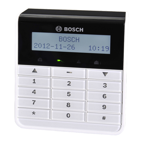
Keypad B920 2-line, LCD 9.1.1
8* 8*
01...08 Similar device
types must use
different
addresses.
Different device
types may use
the same
address.
* Maximum of 8
keypads and 1
RF receiver per
system.
B930 5-line, ATM 9.1.2 01...08
I/O Expander B208 8-input 13.1 4 2 01...08
B308 8-output 11.1 5 3 01...08
RF Receiver B810 Bosch RADION 14.1
1* 1*
1
B820 Inovonics 14.2 1
Power Supply B520 12V DC, 2A 6.3 4 2 01...04
B10 Enclosure
B11 Enclosure
Need more help?
For detailed instructions, refer to the Installation and
System Reference Guide chapter number (ISRG #5.2 )
included on the CD provided with the control panel.
Control Panel Mounting Locations
Attaching Mounting Clips
Technology Location ISRG
#
Terminal Description Specification
18VAC Transformer 18V AC 22VA Plug-in
Earth Ground Cold water pipe, or similar
+ BAT - Battery 12V DC 7Ah
NO C NC Output A Switched AUX, COM, or Dry
COM AUX Aux Power 12V DC, 800mA
R Y G B SDI2 Bus Keypads, SDI2 devices, terminal
and Quickconnect in parallel
1 COM 2 Alarm Inputs 1k Ohm EOL
TMPR Tamper Optional tamper switch
B C Outputs B, C Open collector, 50mA,
active low
RESET Reset Switch Hold 5 seconds to enter or
exit service mode
Heartbeat Slow =normal, Rapid=service
mode
MODULE 1 Plug-in Communication module options
Reporting
Text Messages
Remote RPS Programming
Local RPS Programming
iOS Remote Security App
Ethernet On-board 7.5
Cellular B440
Plug-in 8.2
Telephone B430
Plug-in 7
USB On-board 3.3.8
Transformer
2
1
RPS Programming Keypad Programming
Remote Programming Software (RPS)
• Windows based account management and control
panel programming application
• Each control panel program is represented as an
RPS database record
RPS Features
• Full control panel configuration, local, and remote
• Control panel firmware updates, local, and
remote
• Control panel history event management and
reports
• Enhanced remote panel diagnostics
RPS Ordering Information
• D5500CU: RPS Account management and control
panel programming software on CD-ROM
• D5370-USB: USB Security Block (Dongle)
Security accessory required for RPS to control
panel communications
• D5500C-USB: RPS software and required USB
Security Block (Dongle) kit
USB Security Block
RPS Software Download: http://tiny.cc/boschrps
Note: RPS version 5.15 or higher is required for
connection to B Series control panels.
RPS Installation and Initial Login
• Install RPS on a Windows PC
• Login to RPS using the following credentials
• User Name: admin
• Password: default
• Change the password after initial login
RPS Help
Press F1 for context sensitive help from any
window or programming field within the RPS
application.
Creating B Series Accounts
1. Panel List > New
2. Select a B Series control panel
3. Enter the account information in the fields
B Series Panel Configuration
1. To open, double-click the B Series account.
2. Complete the required basic control panel
parameters.
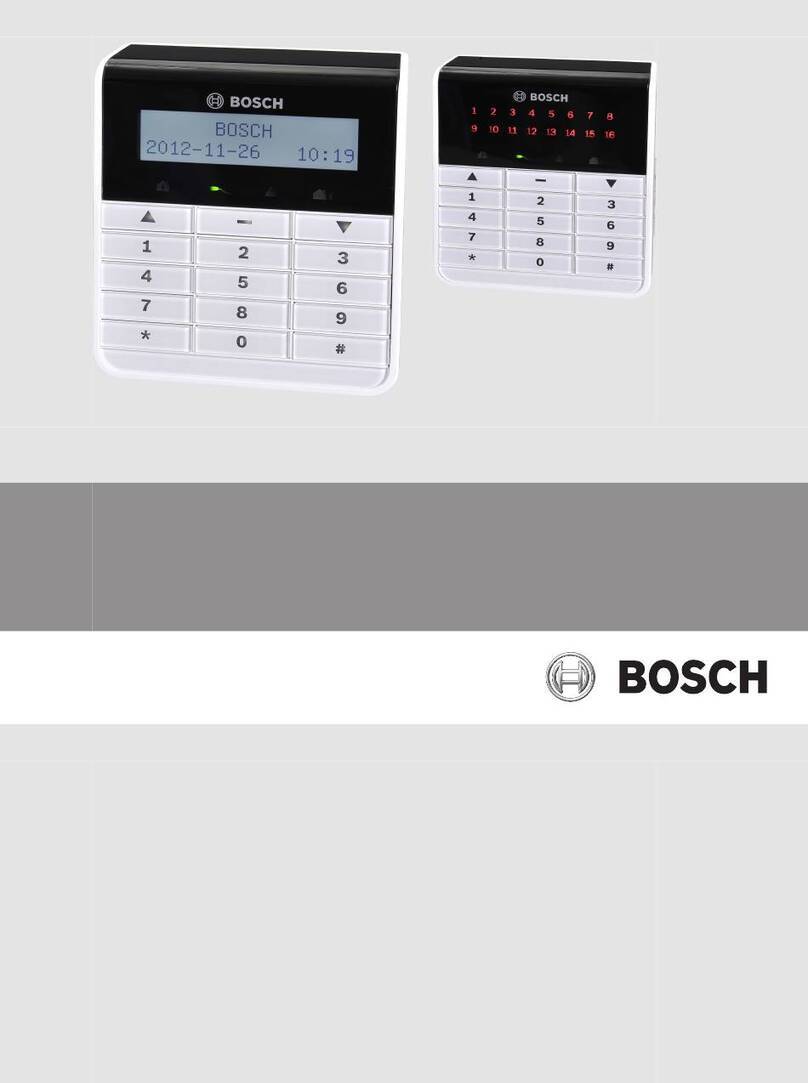
B930 ATM Style Alphanumeric Keypad Features:
• Bright five-line display
• Four ATM style soft-keys on both sides of the
display
B920 Two-line Alphanumeric Keypad Features:
• Bright two line display
• Eight dedicated function keys
B Series Keypad Functions
• System operation (User)
• System diagnostics (Installer)
• Basic Panel Programming (Installer)
Installer Mode
• Installer Mode provides basic programming and
diagnostics at system keypads.
• Installer Mode tools include:
• Programming
• Wireless
• Network
• Enter Installer Mode by entering the default
installer passcode: [1][2][3][ENTER].
• Exit Installer Mode by pressing [ESC].
• Service Bypass
• Versions
• Cellular
Service Mode
• Service Mode differs from Installer Mode by:
• Stopping all reporting
• Enabling a service keypad (address 0,0)
• Rebooting control panel when mode is exited
• Entering Service Mode:
1. Hold the panel’s RESET button for 5 seconds
(Heartbeat LED pulses rapidly).
2. Press [1][2][3][ENTER].
• Exiting Service Mode:
Hold the panel’s RESET button for 5 seconds
(Heartbeat LED stops and the control panel
reboots).
Keypad Programming
Programming needed to make a system operational
includes reporting and point programming.
Point Programming Process
1. Enter the Points Menu.
2. Select a Point Number.
3. Set the Point Source.
4. Assign a Point Index.
Point Source: Identifies the source (device type) of
the point being programmed.
If the source selected is Wireless an RFID option is
presented. Wireless RFID numbers are found on
the wireless device being added.
Point Index: Device (point) behavior characteristics
assigned to each point in the system.
Twenty Point Indexes are provided including the
following common device functions:
4 – Smoke Detectors
7 – Perimeter Door/Window, no Entry
8 – Perimeter Entry/Exit Door
13 – Interior Motion Detector
Important Notes:
• Change the default ([1][2][3]) installer passcode.
• Test system via Main Menu > Actions > Test menu.
• Central Station receiver update is required when
using Conettix IP and Modem4 reporting format.
Need help? Press the keypad HELP key.
Connecting to B Series Conrol Panels
1. Plug in the Security Block.
2. Click the Connect button.
3. Select the connection method.
4. Connect to the control panel.
5. Send All programming parameters to the control
panel.
© 2013 Bosch Security Systems, Inc.
2013.01
F01U279696-06
Other manuals for B5512

2

This manual suits for next models

1

Other Bosch Control Panel manuals

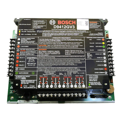
Bosch DS7400XiV4-EXP User manual

Bosch

Bosch DS7400XiV4-EXP User manual

Bosch D7212GV3 Quick start guide

Bosch

Bosch D7212GV3 Quick start guide

Bosch D7412GV2 Quick start guide

Bosch

Bosch D7412GV2 Quick start guide

Bosch D9412GV2 Troubleshooting guide

Bosch

Bosch D9412GV2 Troubleshooting guide

Bosch Solution 880 User manual

Bosch

Bosch Solution 880 User manual

Bosch Solution 2000 User manual

Bosch

Bosch Solution 2000 User manual

Bosch DS3MX-E-U User manual

Bosch

Bosch DS3MX-E-U User manual

Bosch FPA-5000 User guide

Bosch

Bosch FPA-5000 User guide

Bosch MPC-xxxx-B User manual

Bosch

Bosch MPC-xxxx-B User manual

Bosch FPA-5000 User manual

Bosch

Bosch FPA-5000 User manual

Bosch B6512 Instruction manual

Bosch

Bosch B6512 Instruction manual

Bosch FPD-7024 User manual

Bosch

Bosch FPD-7024 User manual

Bosch 2000 Series Troubleshooting guide

Bosch

Bosch 2000 Series Troubleshooting guide

Bosch D9412GV4 Troubleshooting guide

Bosch

Bosch D9412GV4 Troubleshooting guide

Bosch Solution 880 CC408 User manual

Bosch

Bosch Solution 880 CC408 User manual

Bosch D9412GV2 User manual

Bosch

Bosch D9412GV2 User manual

Bosch B9512G User manual

Bosch

Bosch B9512G User manual

Bosch BE 300 LSN User manual

Bosch

Bosch BE 300 LSN User manual

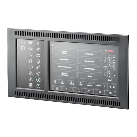
Bosch MPC-xxxx-C Series User manual

Bosch

Bosch MPC-xxxx-C Series User manual

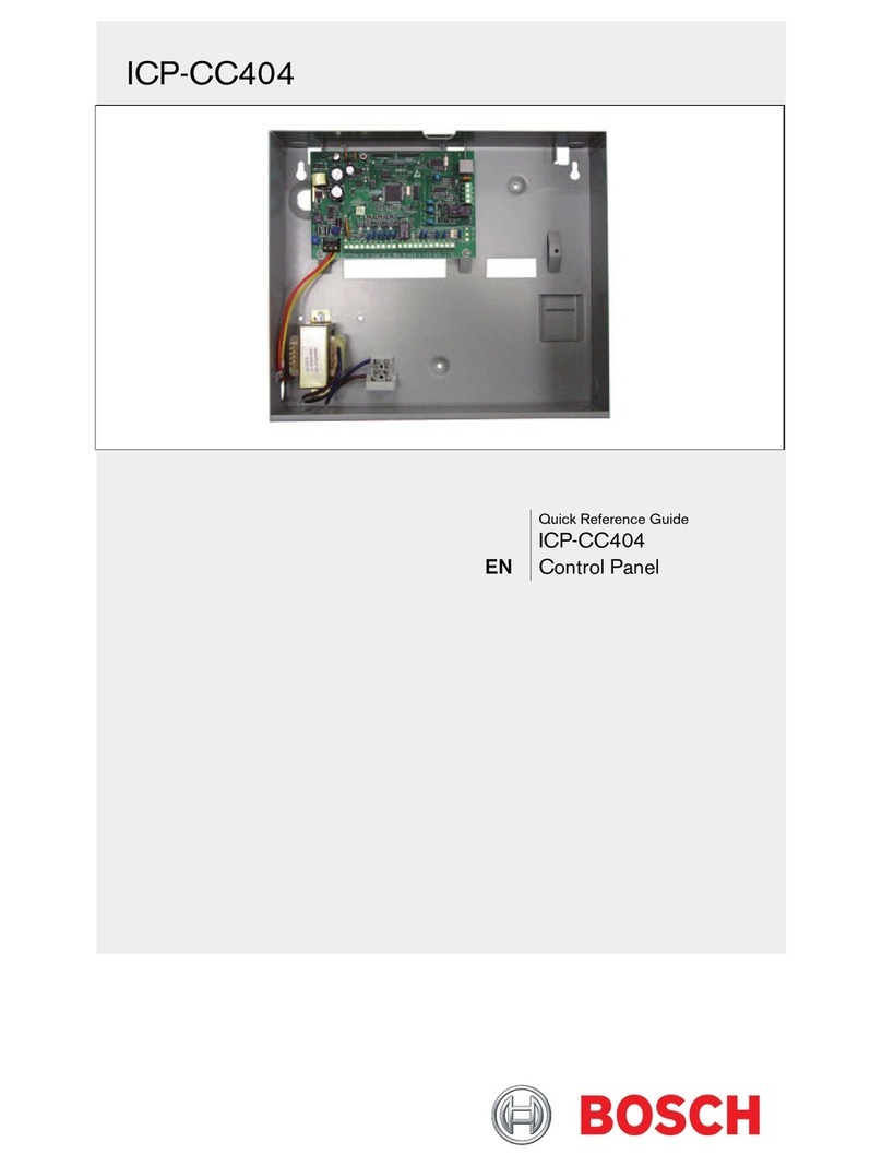
Bosch ICP-CC404 User manual

Bosch

Bosch ICP-CC404 User manual

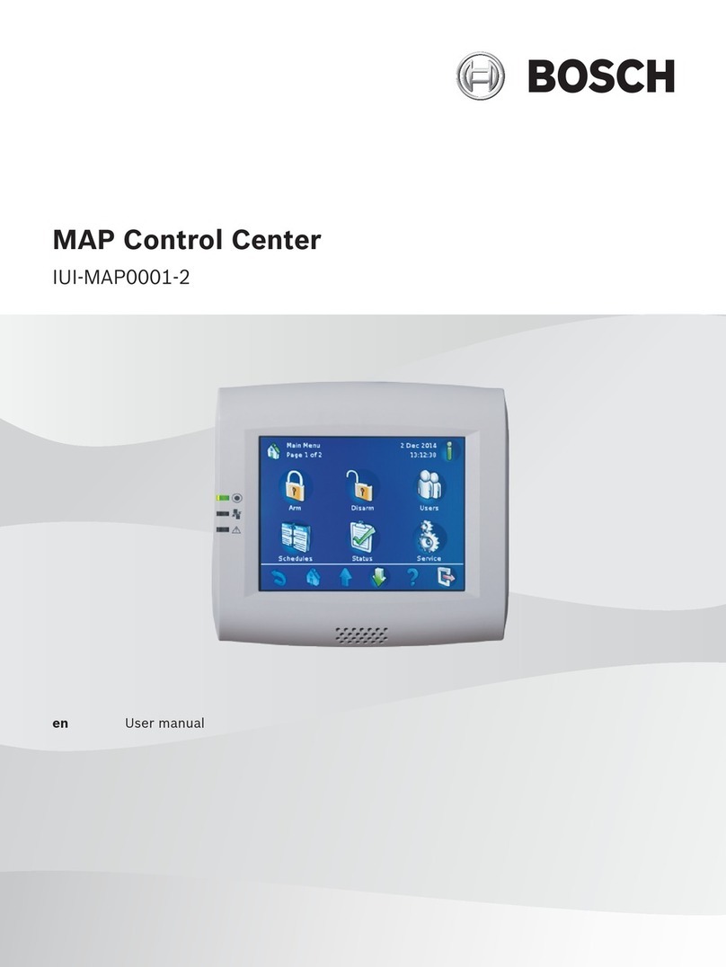
Bosch AMAX panel 2000 ICP-AMAX-P User manual

Bosch

Bosch AMAX panel 2000 ICP-AMAX-P User manual

Bosch D9412GV2 User manual

Bosch

Bosch D9412GV2 User manual

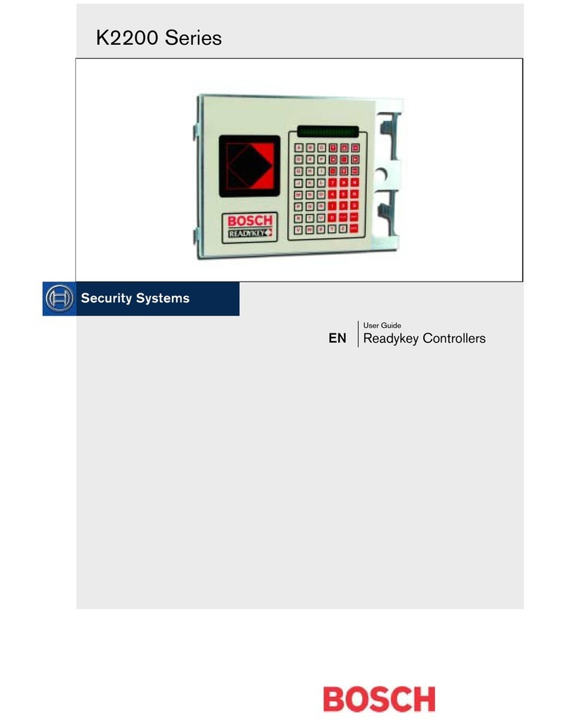
Bosch K2200 Series User manual

Bosch

Bosch K2200 Series User manual

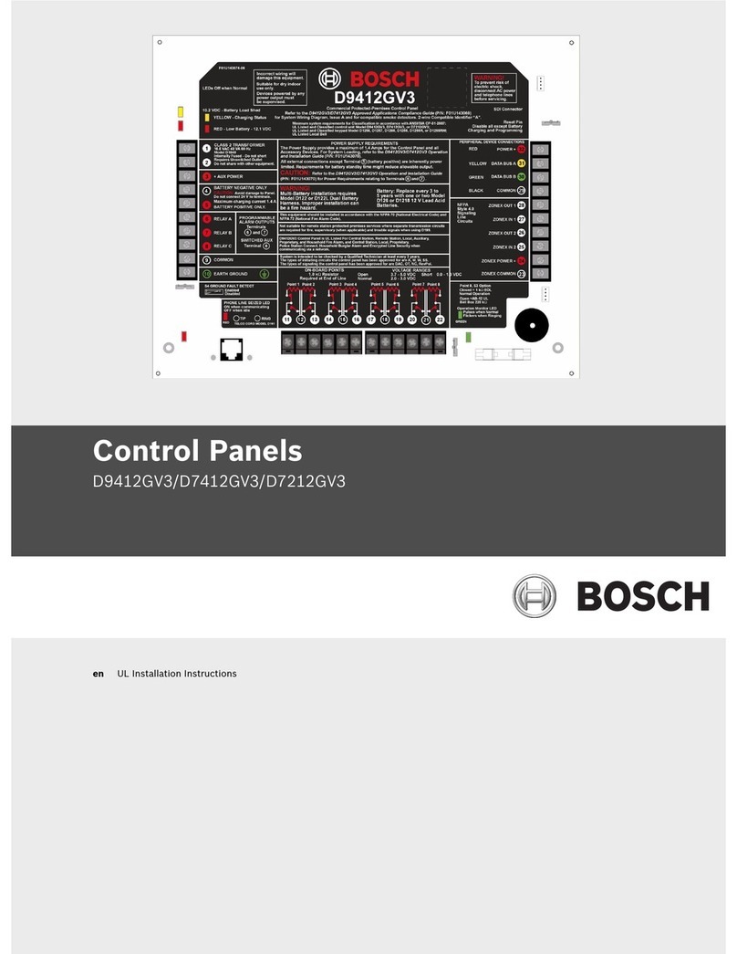
Bosch D9412GV3 Troubleshooting guide

Bosch

Bosch D9412GV3 Troubleshooting guide

Popular Control Panel manuals by other brands

Telex LCP-16 installation guide

Telex

Telex LCP-16 installation guide

Ness pro-lx user manual

Ness

Ness pro-lx user manual

Potter PFC-100RC Installation, operation and instruction manual

Potter

Potter PFC-100RC Installation, operation and instruction manual

Honeywell SILENT KNIGHT 6700 manual

Honeywell

Honeywell SILENT KNIGHT 6700 manual

ESAB Caddy TA33 instruction manual

ESAB

ESAB Caddy TA33 instruction manual

Bpt Mitho Series manual

Bpt

Bpt Mitho Series manual

Siemens SINAMICS G130 operating instructions

Siemens

Siemens SINAMICS G130 operating instructions

Tyco Fire & Security CWSI CP-3600 Operating and installation instruction manual

Tyco Fire & Security

Tyco Fire & Security CWSI CP-3600 Operating and installation instruction manual

Honeywell Notifier NFS2-640/E Programming manual

Honeywell

Honeywell Notifier NFS2-640/E Programming manual

St. Croix DHC3000 instructions

St. Croix

St. Croix DHC3000 instructions

FAAC Estate Swing E-SL 1800 installation manual

FAAC

FAAC Estate Swing E-SL 1800 installation manual

ABB CP 600 Series operating instructions

ABB

ABB CP 600 Series operating instructions

Teletek electronics MAG4 user manual

Teletek electronics

Teletek electronics MAG4 user manual

Bentel Security Academy 4 Programming guide

Bentel Security

Bentel Security Academy 4 Programming guide

Honeywell Notifier NFS-320/E/C Operation manual

Honeywell

Honeywell Notifier NFS-320/E/C Operation manual

Sigma K1000 Series Operation & maintenance manual

Sigma

Sigma K1000 Series Operation & maintenance manual

Riello CPD 30 quick start guide

Riello

Riello CPD 30 quick start guide

Norac UC5 ECHO Display Kit installation manual

Norac

Norac UC5 ECHO Display Kit installation manual

manuals.online logo
manuals.online logoBrands
  • About & Mission
  • Contact us
  • Privacy Policy
  • Terms and Conditions

Copyright 2025 Manuals.Online. All Rights Reserved.