10 | English
1 609 92A 3R5 | (5.2.18) Bosch Power Tools
English
Safety Notes
All instructions must be read and observed
in order to work safely with the measuring
tool. The integrated protections in the
measuring tool may be compromised if the
measuring tool is not used in accordance
with the instructions provided. Never make warning signs
on the measuring tool unrecognisable. STORE THESE IN-
STRUCTIONS IN A SAFE PLACE AND INCLUDE THEM WITH
THE MEASURING TOOL WHEN GIVING IT TO A THIRD PAR-
TY.
Caution – The use of other operating or adjusting
equipment or the application of other processing meth-
ods than those mentioned here can lead to dangerous
radiation exposure.
The measuring tool is provided with a warning label
(marked with number 14 in the representation of the
measuring tool on the graphics page).
If the text of the warning label is not in your national
language, stick the provided warning label in your na-
tional language over it before operating for the first
time.
Do not direct the laser beam at persons
or animals and do not stare into the di-
rect or reflected laser beam yourself, not
even from a distance. You could blind
somebody, cause accidents or damage
your eyes.
If laser radiation strikes your eye, you must deliberate-
ly close your eyes and immediately turn your head
away from the beam.
Do not make any modifications to the laser equipment.
Do not use the laser viewing glasses as safety goggles.
The laser viewing glasses are used for improved visualisa-
tion of the laser beam, but they do not protect against laser
radiation.
Do not use the laser viewing glasses as sun glasses or in
traffic. The laser viewing glasses do not afford complete
UV protection and reduce colour perception.
Have the measuring tool repaired only through quali-
fied specialists using original spare parts. This ensures
that the safety of the measuring tool is maintained.
Do not allow children to use the laser measuring tool
without supervision. They could unintentionally blind
other persons or themselves.
Do not operate the measuring tool in explosive environ-
ments, such as in the presence of flammable liquids,
gases or dusts. Sparks can be created in the measuring
tool which may ignite the dust or fumes.
Do not use the measuring tool if the display glass is vis-
ibly damaged (e.g. cracks in the surface, etc.). This pos-
es a risk of injury.
Caution! When using the measuring tool with
Bluetooth®, interference with other devices and sys-
tems, airplanes and medical devices (e.g., cardiac
pacemakers, hearing aids) may occur. Also, the possi-
bility of humans and animals in direct vicinity being
harmed cannot be completely excluded. Do not use the
measuring tool with Bluetooth®in the vicinity of medi-
cal devices, petrol stations, chemical plants, areas
where there is danger of explosion, and areas subject
to blasting. Do not use the measuring tool with Blue-
tooth®in airplanes. Avoid operation in direct vicinity of
the body over longer periods.
The Bluetooth®word mark and logos are registered trade-
marks owned by Bluetooth SIG, Inc. and any use of such
marks by Robert Bosch Power Tools GmbH is under li-
cence.
Product Description and
Specifications
Please unfold the fold-out page with the representation of the
measuring tool and leave it unfolded while reading the operat-
ing instructions.
Intended Use
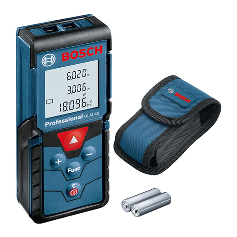
The measuring tool is intended for measuring distances,
lengths, heights, clearances and inclines, and for calculating
areas and volumes.
The measuring results can be transferred to other devices via
Bluetooth®.
Technical Data
Digital Laser Measure GLM 150 C
Article number 3 601 K72 F..
Measuring range (typical) 0.08–150 mA)
Measuring range (typical under
unfavourable conditions) 60 mB)
Measuring accuracy (typical) ±1.5mmA)
Measuring accuracy (typical un-
der unfavourable conditions) ±3.0mmB)
Lowest indication unit 0.5 mm
Indirect Distance Measure-
ment and Vial
Measuring range 0°–360°(4x90°)
OBJ_BUCH-3335-003.book Page 10 Monday, February 5, 2018 10:58 AM


