8| Deutsch
1 609 92A 2P5 | (14.11.16) Bosch Power Tools
Deutsch
Sicherheitshinweise
Allgemeine Sicherheitshinweise
Lesen Sie alle dem Arbeitstisch oder dem zu
montierenden Elektrowerkzeug beigefüg-
ten Warnhinweise und Anweisungen. Ver-
säumnisse bei der Einhaltung der Sicherheits-
hinweise und Anweisungen können
elektrischen Schlag, Brand und/oder schwere
Verletzungen verursachen.
Sicherheitshinweise für Arbeitstische
Ziehen Sie den Stecker aus der Steckdose und/oder
entnehmen Sie den Akku vom Elektrowerkzeug, bevor
SieGeräteeinstellungen vornehmenoderZubehörteile
wechseln. UnbeabsichtigterStart vonElektrowerkzeugen
ist die Ursache einiger Unfälle.
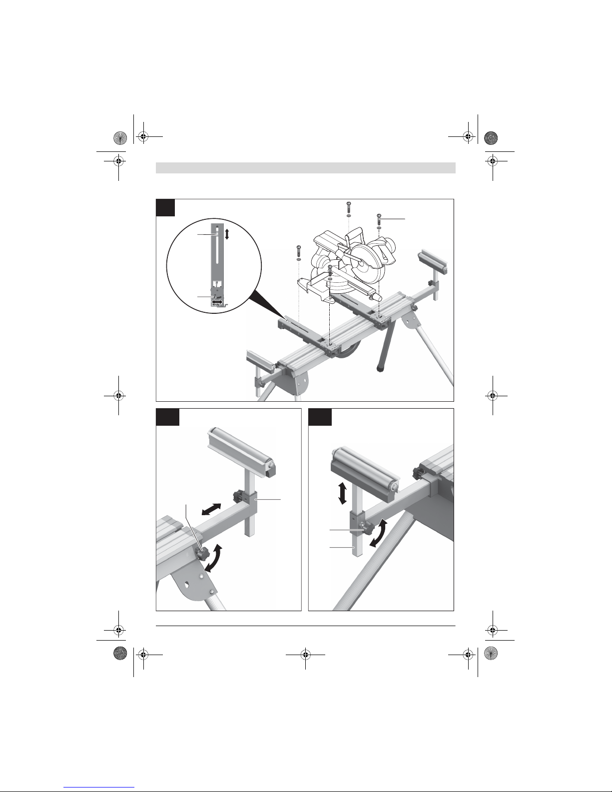
Bauen Sie den Arbeitstisch korrekt auf, bevorSie das
Elektrowerkzeug montieren. Einwandfreier Aufbau ist
wichtig, um das Risiko eines Zusammenbrechens zu ver-
hindern.
Befestigen Sie das Elektrowerkzeug sicher am Arbeits-
tisch, bevor Sie es benutzen. Ein Verrutschen des Elekt-
rowerkzeugs auf dem Arbeitstisch kann zum Verlust der
Kontrolle führen.
Stellen Sie den Arbeitstisch auf eine feste, ebene und
waagerechte Fläche. Wenn der Arbeitstisch verrutschen
oder wackeln kann, können das Elektrowerkzeug oder das
Werkstück nicht gleichmäßig und sicher geführt werden.
Überlasten Sie den Arbeitstisch nicht und verwenden
Sie diesen nicht als Leiter oder Gerüst. Überlastung
oder Stehen auf dem Arbeitstisch kann dazu führen, dass
sich der Schwerpunkt des Arbeitstischs nach oben verla-
gert und dieser umkippt.
Achten Sie darauf, dass beim Transport und beim Ar-
beiten sämtliche Schrauben und Verbindungselemen-
te fest angezogen sind. Die Aufnahme-Sets für das
Elektrowerkzeug müssen immer fest arretiert sein. Lo-
ckere Verbindungen können zu Instabilitäten und unge-
nauen Sägevorgängen führen.
Montieren und demontieren Sie das Elektrowerkzeug
nur, wenn es in Transportstellung ist (Hinweise zur
Transportstellung siehe auch Betriebsanleitung des je-
weiligen Elektrowerkzeugs). Das Elektrowerkzeug kann
sonst einen so ungünstigen Schwerpunkt haben, dass Sie
es nicht sicher halten können.
Betreiben Sie das auf dem Aufnahme-Set befestigte
Elektrowerkzeug ausschließlich auf dem Arbeitstisch.
Ohne den Arbeitstisch steht das Aufnahme-Set mit dem
Elektrowerkzeug nicht sicher und kann kippen.
StellenSie sicher,dass langeund schwereWerkstücke
denArbeitstisch nichtaus demGleichgewicht bringen.
Lange und schwere Werkstücke müssen am freien Ende
unterlegt oder abgestützt werden.
Bringen Sie beim Zusammenschieben oder Auseinan-
derziehen des Arbeitstisches ihre Finger nicht in die
Nähe der Gelenkpunkte. Die Finger könnten einge-
quetscht werden.
Symbole
Die nachfolgenden Symbole können für den Gebrauch Ihres
Arbeitstisches von Bedeutung sein. Prägen Sie sich bitte die
Symbole und ihre Bedeutung ein. Die richtige Interpretation
der Symbole hilftIhnen,den Arbeitstisch besser undsicherer
zu gebrauchen.
Produkt- und Leistungsbeschreibung
Bestimmungsgemäßer Gebrauch
Der Arbeitstisch ist bestimmt, folgende Stationärsägen von
Bosch aufzunehmen (Stand 2012.08):
Ausgewählte Kapp- und Gehrungssägen anderer Hersteller
können ebenfalls montiert werden.
Zusammen mit dem Elektrowerkzeug ist der Arbeitstisch be-
stimmt zum Ablängen von Brettern und Profilen.
Abgebildete Komponenten
Die Nummerierung der abgebildeten Komponenten bezieht
sich auf die Darstellung des Arbeitstisches auf den Grafiksei-
ten.
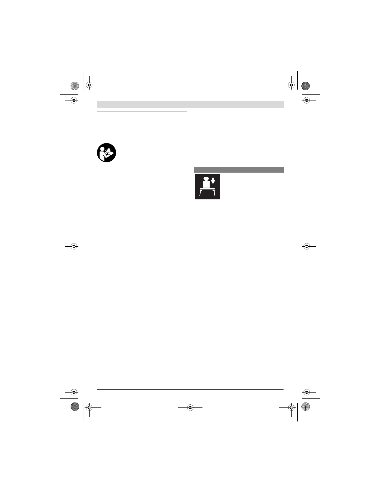
1Werkstückauflage
2Feststellknauf der Werkstückauflage 1
3Tischverlängerung
4Längenanschlag
5Aufnahme-Set
6Rollenauflage
7Feststellknauf der Tischverlängerung 3
8Höhenverstellbarer Fuß
9Tragegriff
10 Gabelschlüssel (13 mm)
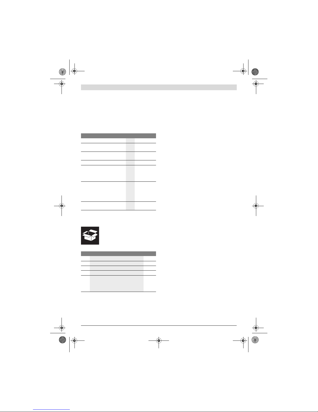
Symbol Bedeutung
Die maximale Tragfähigkeit (Elektro-
werkzeug + Werkstück) des Arbeitsti-
sches beträgt 250 kg.
– GCM 8 S 3 601 L16 0..
– GCM 8 SJ 3 601 L16 2..
– GCM 800 S 3 601 L16 1..
– GCM 10 0 601 B20 0..
–GCM10J
GCM 10 M 3 601 M20 2..
– GCM 10 S 0 601 B20 5..
– GCM 10 SD 0 601 B22 5..
– GCM 12 0 601 B21 0..
– GCM 12 GDL 3 601 M23 6..
– GCM 12 SD 0 601 B23 5..
– GTM 12 3 601 M15 0..