IT INSTALLAZIONE
DA INCASSO
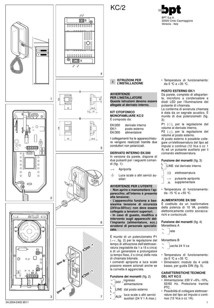
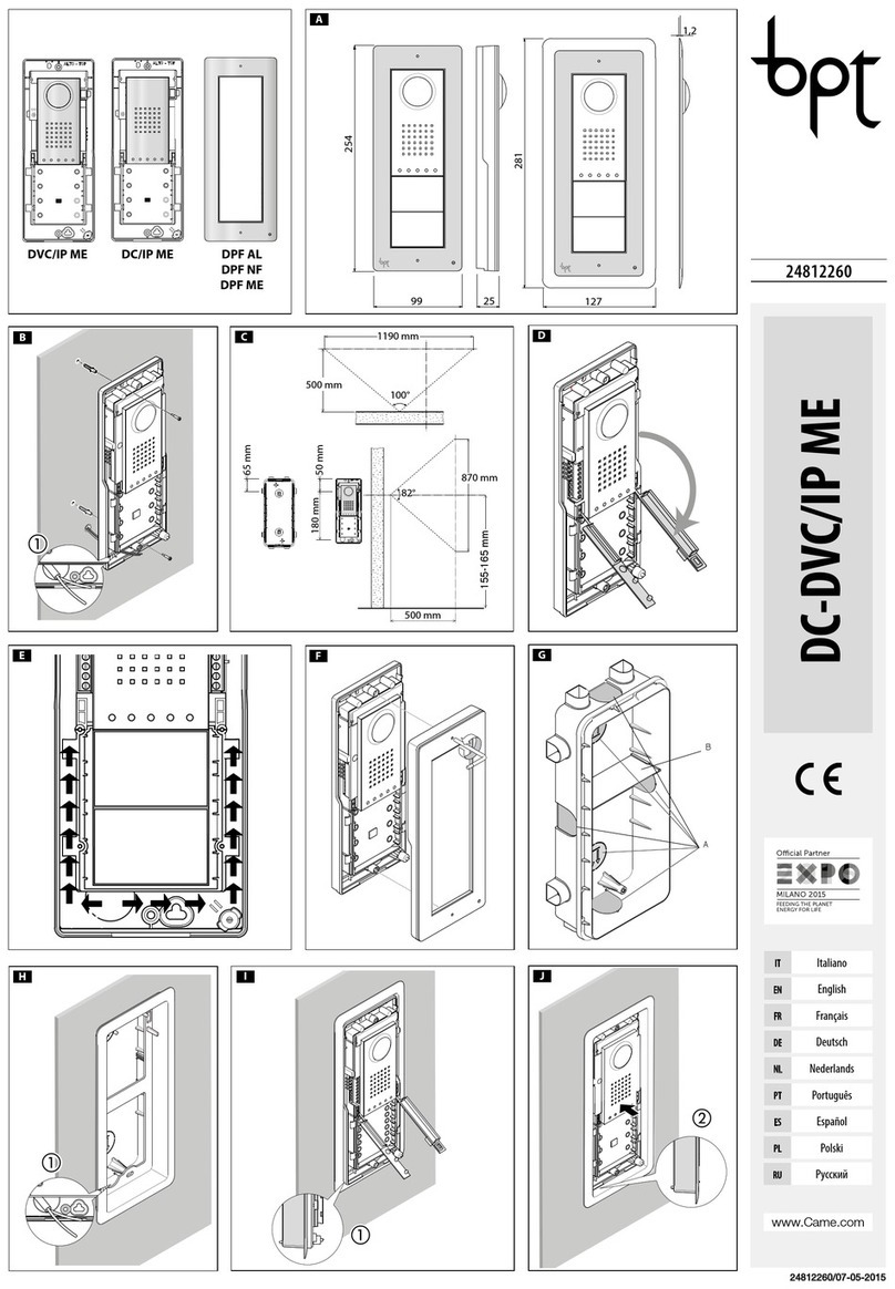
• Murare la scatola d’in-
casso all’altezza desiderata
tenendo conto del posizio-
namento dell’obiettivo della
telecamera (figura 3-A) e facendo
preventivamente passare la tubazio-
ne con i conduttori d’impianto attra-
verso uno dei punti a rottura (figura
3-B punto A).
Nella messa in opera della scatola
d’incasso si potranno evitare possibili
deformazioni utilizzando l’apposito
distanziale in dotazione (figura 3-B
punto B).
• Tramite la chiave a brugola svitare le
viti di bloccaggio e togliere la placca
del posto esterno (figura 1-B).
• Introdurre i cavi di collegamento
nell’apposito foro (figura 2-A) e fissa-
re il posto esterno sulla cornice come
indicato in figura 4-B; estrarre il co-
primorsetto in plastica ed effettuare
i collegamenti (figura 4-A).
• Una volta terminati i collegamenti
reinserire i coprimorsetti.
• Per il montaggio degli accessori fare
riferimento al capitolo “Montaggio
Moduli Pulsante”.
• Effettuare le operazioni di program-
mazione e regolazioni del posto
esterno secondo quanto descritto
nel “Manuale Programmazione”.
• Montare la placca frontale (figura
1-B).
EN RECESSED INSTALLATION
• Install the recessed box at the desired
height considering the position of
the lens of the camera (figure 3-A),
but in advance, run the hose with the
system conductors through one of
the breaking points (figure 3-B point
A).
• During installation of the recessed
box it is possible to avoid any de-
formation by using the provided
spacer (figure 3-B point B).
• With the allen wrench unscrew the
blocking screws and remove the
entry panel plate (figure 1-B).
• Introduce the cable connections
in the special hole (figure 2-A) and
fix the entry panel on the frame as
shown in figure 4-B; extract the plas-
tic terminal cover and wire the con-
nections (figura 4-A).
• Once the connections have been
made and re-insert the terminal cov-
ers.
• For the installation of the accessories
refer to the chapter “Button module
Installation”.
• Perform the programming and ad-
justment operations of the entry
panel as described in the “Program-
ming Manual”.
• Install the front plate (figure 1-B).
DE UNTERPUTZMONTAGE
• Den Unterputzkasten unter Berück-
sichtigung der Objektivstellung der
Fernsehkamera (Abbildung 3-A) in
der gewünschten Höhe einbauen,
zuvor die Rohrleitung mit den An-
lagenleitern durch einen der Aus-
brechpunkte (Abbildung 3-B Punkt
A) ziehen.
Beim Einsetzen des Unterputzkastens
können Verformungen vermieden
werden, wenn man den beiliegen-
den Abstandshalter (Abbildung 3-B
Punkt B) benutzt.
• Mit dem Inbusschlüssel die Befesti-
gungsschrauben herausdrehen und
das Tableau der Außenstation abneh-
men (Abbildung 1-B).
• Die Anschlusskabel durch die Aus-
sparung ziehen (Abbildung 2-A)
und die Außenstation, wie in der
Abbildung 4-B gezeigt, auf dem
Abdeckrahmen festmachen; die
Klemmenabdeckung aus Kunststoff
herausziehen und die Anscxhlüsse
ausführen (Abbildung 4-A).
• Nachdem die verbindungen zu ende
gebracht sind, bitte klemmdeckun-
gen wieder einsetzen
• Für die Montage des Zubehörs im
Kapitel “Montage Tastenmodule”
nachlesen.
• Die Außenstation, wie im Handbuch
“Programmierung Beschrieben”, pro-
grammieren und einstellen.
• Das vordere Tableau montieren (Ab-
bildung 1-B).
FR INSTALLATION À ENCASTRER
• Murer le boîtier à encastrer à la hau-
teur souhaitée en tenant compte du
positionnement de l’objectif de la
caméra (figure 3-A) et en faisant préa-
lablement passer la canalisation avec
les conducteurs de l’installation à tra-
vers un des points de rupture (figure
3-B point A).
Lors de la mise en place du boîtier à
encastrer, éviter de possibles défor-
mations en utilisant la douille fournie
et prévue à cet effet (figure 3-B point
B).
• À l’aide de la clé à six pans, dévisser
les vis de blocage et retirer la plaque
du poste extérieur (figure 1-B).
• Introduire les câbles de branchement
dans le trou prévu à cet effet (figure
2-A), fixer le poste extérieur sur le
cadre comme indiqué à la figure 4-B;
extraire le cache-borne en plastique
et effectuer les branchements (figure
4-A).
• Une fois terminés les branchements
et réinsérer les cache-bornes.
• Pour le montage des accessoires, se
référer au chapitre “Montage des mo-
dules bouton”.
• Effectuer les opérations de program-
mation et les réglages du poste exté-
rieur comme décrit dans la “Manuel
Programmation”.
• Monter la plaque frontale (figure 1-B).
ES INSTALACIÓN EMPOTRADA
• Empotre la caja a la altura deseada
teniendo en cuenta la colocación del
objetivo de la cámara (figura 3-A), tras
pasar el tubo con los conductores de
la instalación a través de uno de los
orificios precortados (figura 3-B pun-
to A).
Durante la instalación de la caja em-
potrable se podrán evitar posibles
deformaciones utilizando el distan-
ciador suministrado (figura 3-B punto
B).
• Usando la llave Allen, desenrosque
los tornillos de fijación y quite la placa
de la placa externa (figura 1-B).
• Introduzca los cables de conexión
por el orificio correspondiente (figura
2-A) y fíjela la placa externa contra el
marco, como se muestra en la figura
4-B; quite el cubreborne de plástico y
efectúe las conexiones (figura 4-A).
• Una vez concluidas las conexiones y
vuelva a colocar los cubrebornes.
• Para el montaje de los accesorios,
consulte el capítulo “Montaje de los
módulos de botón”.
• Efectúe las operaciones de progra-
mación y ajustes de la placa externa
según se describe en el “Manual Pro-
gramación”.
• Monte la placa frontal (figura 1-B).
PT INSTALAÇÃO DE EMBUTIR
• Monte a caixa de embutir na parede
à altura desejada tendo em conta a
posição da objectiva da câmara de
vídeo (figura 3-A) e passando previa-
mente o tubo com os condutores de
instalação através de um dos pontos
de ruptura (figura 3-B ponto A).
Ao instalar a caixa de embutir po-
dem-se evitar possíveis deformações
utilizando o específico espaçador for-
necido (figura 3-B ponto B).
• Com a chave allen desaperte os pa-
rafusos de fixação e extraia a placa da
placa botoneira (figura 1-B).
• Introduzir os cabos de ligação no furo
(figura 2-A) apropriado e correção a
placa botoneira externa na moldura
como indicado na figura 4-B; extrair
a cobertura do borne em plástico e
efectuar as ligações (figura 4-A).
• Após ter terminado as ligações e rein-
sira as tampas dos bornes.
• Para a montagem dos acessórios
consulte o capítulo “Montagem dos
módulos botão”.
• Efectue as operações de programa-
ção e regulações da placa botoneira
segundo o descrito no manual “Pro-
gramação”.
• Monte a placa frontal (figura 1-B).
Istruzioni generali di montaggio dei posti esterni
General instructions for assembly of the entry panels
Allgemeine Montageanleitung für die Außenstationen
Instructions générales de montage des postes extérieurs
Instrucciones generales de montaje de las placas externas
Instruções gerais de montagem das placas botoneiras
LC01-LVC01
BPT S.p.A.
Via Cornia, 1
33079 Sesto al Reghena-PN-Italy
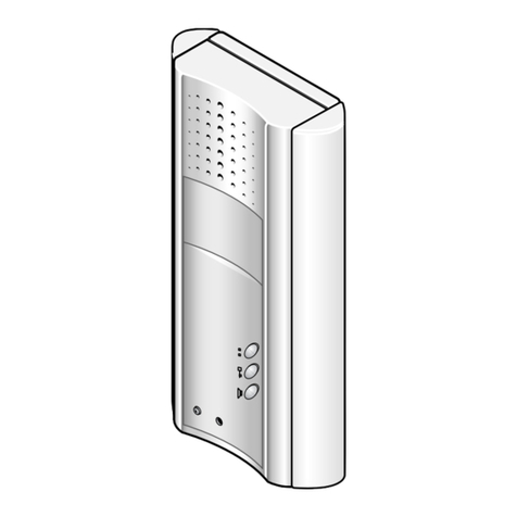
IT CONTENUTO DELL’IMBALLO
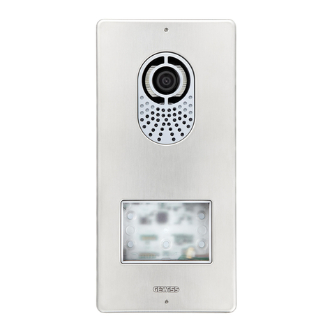
- Posto esterno citofonico/videocitofo-
nico a,
- Chiave a brugola b,
- 2 Tasselli e 2 viti con rosetta c.
EN PACKAGING CONTENTS
- Audio/video entry control a,
- Allen wrench b,
- 2 Plugs and 2 screws with washer
c
.
DE PACKUNGSINHALT
- Außenstation Sprech-/Videosprech-
anlage a,
- Inbusschlüssel b,
- 2 Dübel und 2 Schrauben mit Unter-
legscheibe c.
FR CONTENU DE L’EMBALLAGE
- Poste extérieur d’interphonie/
d’interphonie vidéo a,
- Clé à six pans b,
-
2 Chevilles et 2 vis avec rondelle
c
.
ES
CONTENIDO DEL EMBALAJE
- Placa externa de portero/videoporte-
ro automático b,
- Llave Allen d,
-
2 Tacos y 2 tornillos con arandela
c
.
PT
CONTEÚDO DA EMBALAGEM
-
Placa botoneira de porteiro/vídeo
porteiro
a,
- Chave allen b,
- 2 Buchas e 2 parafusos com anilha c.
a
b
c
A
B
IT - INSTALLAZIONE
DA PARETE
• Tramite la chiave a brugola
svitare le viti di bloccaggio e
togliere la placca (figura 1-A).
• Fissare i tasselli in dotazione e
avvitare il posto esterno (figura 2-A)
all’altezza desiderata tenendo conto
del posizionamento dell’obiettivo della
telecamera (figura 3-A).
Far passare la tubazione con i condut-
tori d’impianto come indicato in figura
2.-A
• Estrarre il coprimorsetto in plastica ed
effettuare i collegamenti (figura 4-A).
• Una volta terminati i collegamenti
reinserire i coprimorsetti.
• Per il montaggio degli accessori fare
riferimento al capitolo “Montaggio mo-
duli pulsante”.
• Effettuare le operazioni di program-
mazione e regolazioni del posto ester-
no secondo quanto descritto nel “Ma-
nuale di programmazione “.
• Montare la placca frontale (figura 1-A).
EN -WALL MOUNTING
• With the allen wrench unscrew the
blocking screws and remove the plate
(figure 1-A).
• Fix the given plugs and screw the
entry panel (figure 2-A) at the desired
height considering the position of the
lens of the camera (figure 3-A).
Run the hose with the system conduct-
ors as shown in figure 2-A.
• Extract the plastic terminal cover and
wire the connections (figure 4-A).
• Once all the connections have been
made, re-insert the terminal covers.
• For the installation of the accessories
refer to the chapter “Button module
installation”.
• Perform the programming and adjust-
ment operations of the entry panel as
described in the “Programming manu-
al”.
• Install the front plate (figure 1-A).
DE - MONTAGE AUFPUTZGEHÄUSE
• Mit dem Inbusschlüssel die Befesti-
gungsschrauben herausdrehen und
das Tableau abnehmen (Abbildung
1-A).
• Die beiliegenden Dübel befestigen
und die Außenstation unter Berück-
sichtigung der Objektivstellung der
Fernsehkamera (Abbildung 3-A) in
gewünschter Höhe anschrauben (Ab-
bildung 2-A).
Wie in Abbildung 2-A gezeigt, die Rohr--A gezeigt, die Rohr- gezeigt, die Rohr-
leitung mit den Anlagenleitern durch-
führen.
• Die Kunststoff-Klemmenabdeckung
entfernen und die Anschlüsse ausfüh-
ren (Abbildung 4-A).
• Nach Abschluss der Anschlussarbei-
ten die Klemmenabdeckungen wieder
einsetzen.
• Für die montage des zubehörs im
kapitel “Montage tastenmodule” na-
chlesen.
• Die Außenstation, wie im Handbuch
“Programmierung” beschrieben, pro-
grammieren und einstellen.
• Das vordere Tableau montieren (Ab-Das vordere Tableau montieren (Ab-
bildung 1-A).
FR - INSTALLATION MURALE
• À l’aide de la clé à six pans, dévisser
les vis de blocage et retirer la plaque
(figure 1-A).
• Fixer les chevilles fournies et visser le
poste extérieur (figure 2-A) à la hauteur
souhaitée en tenant compte du posi-
tionnement de l’objectif de la caméra
(figure 3-A).
Faire passer la canalisation avec les
conducteurs de l’installation comme
indiqué à la figure 2-A.
• Extraire le cache-borne en plastique
et effectuer les branchements (figure
4-A).
• Une fois les branchement terminés,
réinsérer les cache-bornes.
• Pour le montage des accessoires, se
référer au chapitre “Montage des mo-
dules bouton”.
• Effectuer les opérations de program-
mation et les réglages du poste exté-
rieur comme décrit dans la “Manuel
Programmation”.
• Monter la plaque frontale (figure 1-A).
ES -INSTALACIÓN SOBRE PARED
• Usando la llave Allen, desenrosque
los tornillos de fijación y quite la placa
(figura 1-A).
• Fije los tacos suministrados y atornille la
placa externa (figura 2-A) a la altura de--A) a la altura de-) a la altura de-
seada, teniendo en cuenta la colocación
del objetivo de la cámara (figura 3-A).
Pase el tubo con los conductores de
la instalación como se muestra en la
figura 2-A.
• Extraiga el cubreborne de plástico y
realice las conexiones (figura 4-A).
• Una vez concluidas las conexiones,
vuelva a colocar los cubrebornes.
• Para el montaje de los accesorios, con-
sulte el capítulo “Montaje de los módu-
los de botón”.
• Efectúe las operaciones de programa-
ción y ajustes de la placa externa según
se describe en el manual “Programa-
ción”.
• Monte la placa frontal (figura 1-A).
PT - INSTALAÇÃO DE PAREDE
• Com a chave allen desaperte os para-
fusos de fixação e extraia a placa (figura
1-A).
• Fixe as buchas fornecidas e aparafuse a
placa botoneira (figura 2-A) à altura de--A) à altura de-) à altura de-
sejada tendo em conta a posição da ob-
jectiva da câmara de vídeo (figura 3-A).
Passe o tubo com os condutores da
instalação como ilustrado na figura 2-A.
• Extraia a tampa do borne de plástico e
faça as ligações (figura 4-A).
• Após ter terminado as ligações reinsira
as tampas dos bornes.
• Para a montagem dos acessórios con-
sulte o capítulo “Montagem dos módu-
los botão”.
• Efectue as operações de programação
e regulações da placa botoneira segun-
do o descrito no manual “Programação”.
• Monte a placa frontal (figura 1-A).
2-A 4-A
500 mm
1000 mm
77°
94°
800 mm
500 mm
163,5 mm
43,5 mm
3-A
1-A
27-01-2011/24802620
3-B 4-B
2-B
A
B
1-B
LC/01 LVC/01
