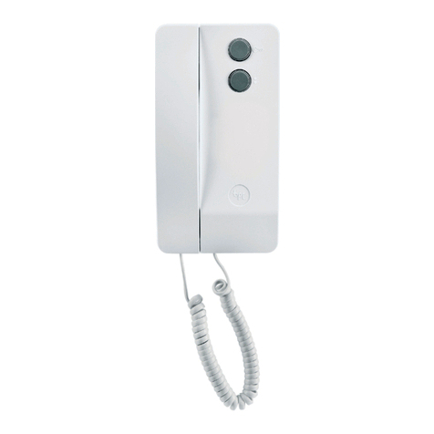
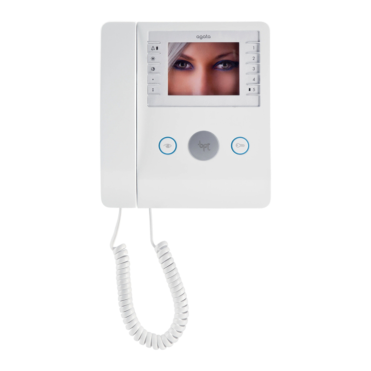
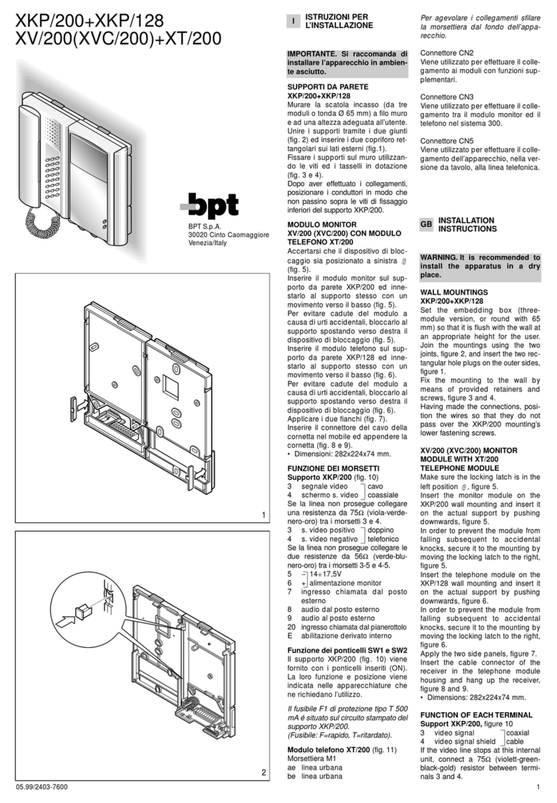
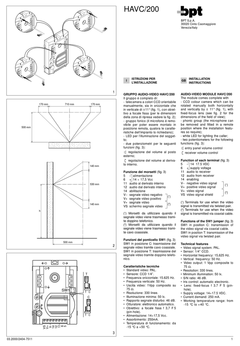
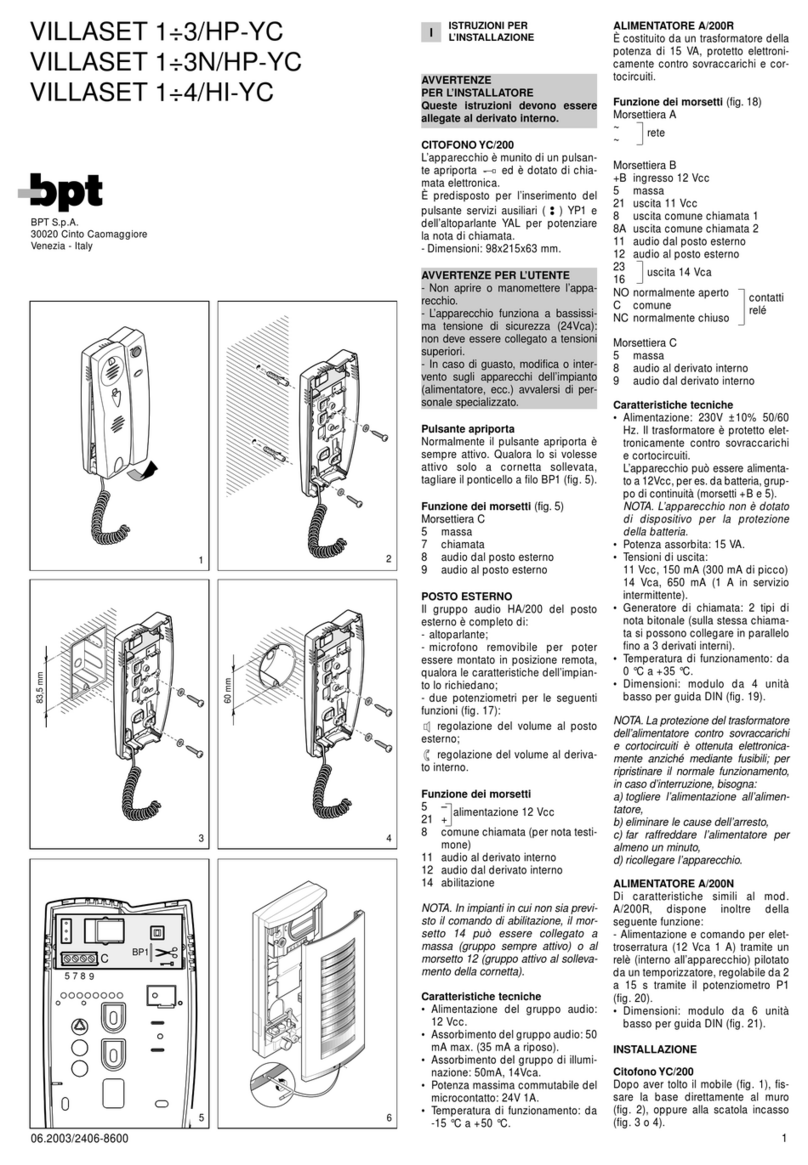
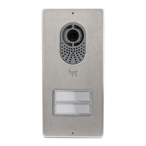
Bpt System 200 Audio O&M User manual

O&M Instructions for use:
CLICK on your chosen part number from
the index on page 2 to take you to the
relevant Technical Data sheet
On the right hand corner of each page
you will find a red oval
click on this to take you to the Index
page

System 200 Audio O&M
Contents Page
HA/200 3
HAC/200 4-7
VLS/101 8
VLS/100C 9
SI/200 10
VSB/200C 11
TT/2 12-14
A/200N 15-16
VAS/100.30 17
CD/200 18
CD/204 19
YC/200 - YC/200A 20
NC/220 - NC/221 21-22
AS/200 - BC/200 23
VSI/200 24
VA/200 25
issue 1.

HA/200
5
21
8
11
12
14
4
2
-15 °C to +50 °C.
AUDIO MODULE HA/200
The unit comes complete with
- loudspeaker;
- microphone which can be remo
-
ved and fitted in a remote positio
n
where the installation features s
o
require;
- two potentiometers for the fo
l-
lowing functions (fig. 4):
entry panel volume control
receiver volume control
Function of each terminal (fig. 4)
5−12 V DC supply voltage
21 +
8common call (for witness note)
11 audio to receiver
12 audio from receiver
14 enabling
NOTE. In installations which do not
cater for the enabling control, termi-
nal 14 can be connected to the earth
(module always on) or terminal 12
(module on only when receiver is lif-
ted).
Technical features
• Supply voltage: 12 VDC.
• Current demand: max. 50 mA (3
5
mA quiescent).
• Working temperature range: from
-15 °C to +50 °C.

01.2001/2404-8900
1
2
3
2
4
GB INSTALLATION
INSTRUCTIONS
-
-
-
CODED-CALL ENTRY
PANEL HAC/200
E
ntry panel with coded call and
n
ame directory for system 200
a
udio and video entry control
i
nstallations and system 100 video
e
ntry control installations.
I
t features a back-lit display for
v
iewing the names and numbers in
t
he directory.
T
he back-lit keypad, made up of
1
8 pushbuttons, lets you send call
c
odes, service codes and alpha-
n
umeric calls using the dedicated
b
uttons.
T
he unit also comes with an RS-
4
85 port so that it can be connec-
t
ed to other similar units and/or PC
f
or entering, transferring and
s
aving names, messages and
codes.
With a storage capacity of approx.
BPT S.p.A.
HAC/200
-codes.
W
ith a storage capacity of approx.
2
,000 secret codes, the unit can be
u
sed for entrance control func-
t
ions.
T
here is no definite number of user
n
ames, messages for the display
a
nd service codes, as this
d
epends on the size of each field.
F
or instance, with a name 12 letters
l
ong, a call code of 6 letters, and 6
n
umbers for the secret codes, over
2
,400 user names can be entered.
Features
-
Option of selecting 3 sizes for the
c
haracters on the display for user
n
ames, informational messages,
p
orter call messages, Tradesman
c
ommand messages and system
b
usy messages.
-
Programming menu which is ena-
b
led once the password is ente-
red.

5
Call code
0-80161 (0-13121) Custom code
_ _ _ _ _ _ _ _ _ _ _ User name
Add
Users management
Lingua/Language Italiano
English
Modify
Delete one
Users deletion ?
Yes/No
Delete all
Block call
Call mode
Progressive call
_ _ _ _ _ _ _ _ _ _ _
_ _ _ _ _ _ _ _ _ _ _
Add
Information texts
Modify
Delete one
_ _ _ _ _ _ _ _ _ _ _
_ _ _ _ _ _ _ _ _ _ _
_ _ _ _ _ _ _ _ _ _ _
_ _ _ _ _ _ _ _ _ _ _
Add
P key texts
Modify
Delete one
T key texts
Busy system texts
0-80
Service codes P key code
80156
T key code
79157
Default block
Call code
0-80161
Add
Secret codes
Modify
Delete one
Lighting mode Fixed ON lighting
Auto ON/OFF light
Setup access code Setup access code
*12345
Add
Modify
Delete one
Add
Modify
Delete one
Add
Modify
Delete one
Export all memory Exporting
memory
Import all memory Overwrite memory
Yes/No Overwrite
memory
Delete all memory Memory deletion?
Yes/No
_ _ _ _ _ _ _ _ _ _ _
_ _ _ _ _ _ _ _ _ _ _
_ _ _ _ _ _ _ _ _ _ _
_ _ _ _ _ _ _ _ _ _ _
_ _ _ _ _ _ _ _ _ _ _
_ _ _ _ _ _ _ _ _ _ _
_ _ _ _ _ _ _ _ _ _ _
_ _ _ _ _ _ _ _ _ _ _
_ _ _ _ _ _ _ _ _ _ _
_ _ _ _ _ _ _ _ _ _ _
_ _ _ _ _ _ _ _ _ _ _
_ _ _ _ _ _ _ _ _ _ _
_ _ _ _ _ _ _ _ _ _ _
_ _ _ _ _ _ _ _ _ _ _
_ _ _ _ _ _ _ _ _ _ _
_ _ _ _ _ _ _ _ _ _ _
_ _ _ _ _ _ _ _ _ _ _
_ _ _ _ _ _ _ _ _ _ _
_ _ _ _ _ _ _ _ _ _ _
_ _ _ _ _ _ _ _ _ _ _
_ _ _ _ _ _ _ _ _ _ _
_ _ _ _ _ _ _ _ _ _ _
_ _ _ _ _ _ _ _ _ _ _
_ _ _ _ _ _ _ _ _ _ _
_ _ _ _ _ _ _ _ _ _ _
_ _ _ _ _ _ _ _ _ _ _
key texts key texts
_ _ _ _ _ _ _ _ _ _ _
Custom code
_ _ _ _ _ _ _ _ _ _ _
_ _ _ _ _ _ _ _ _ _ _
_ _ _ _ _ _ _ _ _ _ _
_ _ _ _ _ _ _ _ _ _ _
_ _ _ _ _ _ _ _ _ _ _
Deletion code
_ _ _ _ _ _ _ _ _ _ _
Codes deletion ?
Yes/No
Delete all
Key block
(0-80)
6
- Programming menu in Italian and
English (select the desired option).
- Messages, names, codes and
parameters entered via the entry
panel’s keypad.
- Option of copying and transfer-
ring the name directory.
- Call code generation in block,
progressive or customized mode.
Function of each terminal
LLON data line
5-supply voltage 14 to 18V DC
6+
7call
8call common
12 call confirmation note attenua-
tion
14 entry panel enabling
I1 input not used
I2 input not used
Technical characteristics
• Display: graphical, back-lit
display, pixel count 122x32
• Supply voltage: 14 to 18V DC
• Current demand: max. 350 mA
• Storage capacity: 1 Mb
• Working temperature range: -15
°C to + 50 °C.
Installation instructions
The front plate can be surface
mounted or recessed using the
relevant kits.
Remove the two plugs protecting the
threaded holes in the embedding
box and secure the chassis using the
two screws supplied (fig. 3).
In order to install the front plate,
first insert the upper part in the top
of the housing (fig. 2) or chassis
(fig. 4), and then tighten the faste-
ning screws using the size 2.5
Allen key supplied.
Function of the buttons for
calling users
Directory search for names
from A to Z.
Scanning performed in this
order of priority: space, spe-
cial characters, number and
letters.
Directory search for names
from Z to A.
Scanning performed in this
order of priority: space, spe-
cial characters, number and
letters.
Call
0÷9 Buttons for entering numerical
codes.
Button for entering alphanu-
meric codes.
CButton for deleting the code or
function on the display.
PButton for a service call (por-
ter call etc.)
SButton to be pressed before
keying in secret codes, pas-
sword for accessing program-
ming and for resetting default
settings.

6
TButton for a service call (tra-
desman stair light etc.).
ENTRY PANEL OPERATING
INSTRUCTIONS
Information for visitors
The entry panel can be program-
med so that, whilst the installation
is in stand-by, information on how
to use the keypad appears on the
display in 4 languages.
These messages can be customi-
zed via programming.
Finding users stored in the
directory and making the call
Pressing and releasing pushbutton
or interrupts the informational
messages so that you can search
for the desired name (along with
the name, the display features the
customized code or, if there is
none, the call code) in alphabetical
order (scanning performed in this
order of priority: space, special
characters, numbers and letters).
Every time the button is pressed,
the next name appears whilst, if the
button is kept pressed, a fast sear-
ch is performed, quickly scrolling
through the initial letters in alpha-
betical order or reverse order
depending on whether key or
is used.
Select the initial letter desired, find
the name using the key or .
When the name desired comes up
on the display, make the call by
pressing the key.
If you know the call code already,
you can also key in the user’s code
directly via the keypad.
System busy warning
This status is indicated on the
display with the previously pro-
grammed message.
Whilst in this condition, calls can-
not be made from the entry panel.
Nonetheless, secret codes can be
sent and the programming menu
accessed.
Key P
A dedicated key for sending the
call code to the porter.
Pressing this key calls up the mes-
sage stored for this function (no
default setting).
If the installation does not feature a
porter switchboard, this code can
be used for other purposes.
Key T
A dedicated key for making a ser-
vice call (tradesman stair light
etc.).
Pressing this key calls up the mes-
sage stored for this function (no
default setting).
Sending this code does not activa-
te the installation.
Key S
This key must be pressed before
entering secret codes.
In order to send a secret code, you
must press the S key, enter the
secret number (no more than 9
numbers) and press the key.
The system features a device that
protects the secret codes from any
attempts to discover them.
Once a code that does not match
any of those stored has been ente-
red 5 times, key P’s service call
code (usually corresponding to the
porter call) is sent.
Key
•Use key in residential installa-
tions to replace the block number
with a letter or caption.
- Press key to select the caption
to be associated with the block
(e.g. A, B, Build. A etc.).
- Key in the user number and press
the key to make the call.
The block code associated with
the caption must be programmed.
•Use key to make alphanume-
ric calls.
- Key can be used to select the
letters. Once the necessary letters
have been stored, simply key in the
alphanumeric code (e.g. AZ, 1C,
A3B etc.), than make the call by
pressing .
Of course, the code entered must
fit in the customized code field in
the user menu.
Key C
Lets you delete the code keyed in.
Accessing the
programming menu
In order to access programming, key
in S 12345 (default setting) and .
Default settings
The entry panel comes with the fol-
lowing settings:
1-Help messages for finding
names in 4 languages (Italian,
English, French, German).
2-Service messages (e.g. BUSY)
in 4 languages (Italian, English,
French, German).
3-Programming menu in Italian
(with the option of selecting
English).
4-CONSTANT LIGHTING mode for
display and keypad.
5-Programming password and
deleting memory S 12345 (S
can be omitted from the memory
deletion password).
6-Block numerical call mode.
7-Block number: 00.
8-Code associated with key P:
80156.
9-Code associated with key T:
79157.
Resetting the default password
Should the customized password
be misplaced, the default setting
12345 can be reset by entering an
emergency code furnished by BPT.
To receive this code, you must
quote the ID code to be found on
the back of the front plate.
Programming button functions
Menu forward search function
Menu reverse search function
Confirms function
0÷9 None
None
CExits programming and returns
to the previous menu function
PNone
SNone
TNone
Data entry button functions
Decreases character size
Increases character size
Confirms data entered
0Enters number 0and symbols
+ - / % £ $
1Enters number 1and symbols
space , : @ ‘ “ ;
2Enters number 2and letters A
BCÅÄÆÇ
3Enters number 3and letters
D E F É
4Enters number 4and letters
G H I
5Enters number 5and letters
J K L
6Enters number 6and letters
MNOÑÖØ
7Enters number 7and letters
PQRSß
8Enters number 8and letters
TUVÜ
9Enters number 9and letters
WXYZ
Enters symbols * . ? ¿ ! ¡ & §
CDeletion of the letter, number
or symbol previously entered
and exit from parameter data
entry.
PEnters symbols # = ( ) < > _
SSelects upper or lower case
TAdvances the cursor across
the display
Programming
menu functions (fig.6)
Lingua/Language
Italiano
English (select the desired langua-
ge for the programming menu
messages).
The language options are Italian
and English.
Users management
Add (adds a new user).
The following parameters can be
entered for each user:
•call code (0-80155)
•customized code (max. 9 num-
bers or letters)
•user name (max. 80 letters in
small characters, max. 30 letters
in medium characters, max. 9
letters in large characters).
WARNING. If you want to enter
users in progressive call mode,
you must first edit the settings in
the relevant section.
Modify (edits the stored user).
Delete one (deletes an individual
stored user).
In the Modify and Delete one sub-
menus, you can select the user to
be edited or deleted using keys
and .
You can scroll through quickly by
keeping key or pressed.
Delete all (deletes all stored users).
In the Delete all submenu, you are
asked to confirm before all stored
items are deleted.
Call mode
Block call (call in block mode).
First two digits: 0 to 80;
Last three digits: 0 to 161.
Progressive call (call in progressi-
ve mode).
0 to 12635.
Information texts
Add (adds a new informational mes-
sage).
Informational messages are ente-
red using the alphanumeric keys
and can contain up to 80 letters and
numbers in small characters, 30 let-
ters and numbers in medium cha-
racters and 9 letters and numbers
for large characters.
Messages are displayed in sequen-
ce every 2 s.
Modify (edits the informational mes-
sage).
Delete one (deletes an informational
message).
In the Modify and Delete one sub-
menus, you can select the message
to be edited or deleted using keys
and .
P key texts
Add (adds anew portercallmessage).
Porter call messages are entered
using the alphanumeric keys and
can contain up to 80 letters and
numbers in small characters, 30
letters and numbers in medium
characters and 9 letters and num-
bers for large characters.
Messages are displayed in
sequence every 2 s.
Modify (edits the porter call messa-
ge).
Delete one (deletes a porter call
message).
In the Modify and Delete one sub-
menus, you can select the messa-
ge to be edited or deleted using
keys and .
T key texts
Add (adds a new Tradesman com-
mand message).
Tradesman command messages
are entered using the alphanume-
ric keys and can contain up to 80
letters and numbers in small cha-
racters, 30 letters and numbers in
medium characters and 9 letters
and numbers for large characters.
Messages are displayed in
sequence every 2 s.
Modify (edits the Tradesman com-
mand message).
Delete one (deletes a Tradesman
command message).
In the Modify and Delete one sub-
menus, you can select the messa-
ge to be edited or deleted using

keys and .
Busy system texts
Add (adds a new system busy
message).
System busy messages are ente-
red using the alphanumeric keys
and can contain up to 80 letters
and numbers in small characters,
30 letters and numbers in medium
characters and 9 letters and num-
bers for large characters.
Messages are displayed in
sequence every 2 sec..
Modify (edits the system busy mes-
sage).
Delete one (deletes a system busy
message).
In the Modify and Delete one sub-
menus, you can select the messa-
ge to be edited or deleted using
keys and .
key texts
Add (adds a new customized
alphanumeric code).
Customized alphanumeric codes
are entered using the alphanume-
ric keys and can contain up to 9
letters and numbers.
You will be asked to enter any
block code (0 to 80) associated
with the alphanumeric one.
Codes are always displayed with
large characters.
Modify (edits the customized
alphanumeric code).
Delete one (deletes a customized
alphanumeric code).
In the Modify and Delete one sub-
menus, you can select the code to
be edited or deleted using keys
and .
Default block
0-80 (block code)
This code is transmitted when
less than 4 digits are keyed in (in
block call mode only).
Service codes
P key code (auxiliary call code sent
to a remote actuator).
If it is used to call the porter, the
user code (last three digits) must
be 156.
The block code (first two digits)
must be given a value in the range
0 to 80 except for the progressive
call mode, where numbers are limi-
ted to 78, 79, 80.
T key code (porter call code sent to
a remote actuator).
You can use all block codes in the
range 0to 80 (first two digits) and
user codes in the range 0to 161
(last three digits).
If the progressive call mode has
been chosen, the range of usable
codes goes from 78000 to 78161,
79000 to 79161, 80000 to 80161.
The codes stored for services are
kept divided into block number and
user number even where the pro-
gressive call mode has been cho-
sen.
Secret codes
Add (adds a new secret code).
You will be asked to enter the call
code to be sent to the remote
actuator.
You can use all codes in the range
0to 80 (for the block code) and in
the range 0to 161 (for the user
code).
If the progressive call mode has
been chosen, the range of usable
codes goes from 78000 to 78161,
79000 to 79161, 80000 to 8016.
You will also be asked to enter the
customized code (password up to
9 numbers long), which may be
given a different value for each
user.
Modify (edits the secret code).
Delete one (deletes a secret code).
In the Modify and Delete one sub-
menus, you can select the code to
be edited or deleted using keys
and .
You can scroll through quickly by
keeping key or pressed.
Delete all (deletes all secret
codes).
In the Delete all submenu, you are
asked to confirm before all secret
codes are deleted.
The codes stored for services are
kept divided into block number and
user number even where the pro-
gressive call mode has been cho-
sen.
Lighting mode
Fixed ON lighting (display and key-
pad lighting always on).
Auto ON/OFF light (lighting swit-
ched off automatically after 1
minute).
The key remains lit at all times.
Setup access code
12345 (default setting).
Password for accessing pro-
gramming menu.
The password is entered using the
numerical keys and can be up to 8
numbers long.
In order to access the programming
menu, the password must always
be preceded by the S key and .
Export all memory
Exporting memory?
Once the export procedure has
been started, it can be stopped
using key C.
WARNING. In order to use this
function, terminals L in the entry
panels must be connected with a
twisted pair (see relevant installa-
tion diagram).
Import all memory
Overwrite memory. Yes/No
You will be asked to confirm
before the device’s memory is
overwritten.
WARNING. In order to use this
function, terminals L in the entry
panels must be connected with a
twisted pair (see relevant installa-
tion diagram).
Delete all memory
Memory deletion? Yes/No
You will be asked to confirm
before the device’s memory is
deleted.
Deletion code
Enter the password for acces-
sing the programming menu in
order to delete the memory.
Copy memory between 2
HAC/200 units
1)Set the entry panel HAC/200 to
copy in export mode, then set the
other HAC/200 entry panel to
import mode.
2) Confirm transfer and wait until i
t
is complete.
The copy does not include the lan
-
guage, call mode, block defaul
t
setting, service codes, lighting
mode and programming pas
-
sword.

VLS/101
06.2002/2402-1022
A
1
B
2345
321
43,5
45
7,5 57
70
106
A
B
64,5
70
145
1
2
BPT S.p.A.
30020 Cinto Caomaggiore
Venezia - Italy
GB INSTALLATION
INSTRUCTIONS
RELAY MODULE VLS/101
The relay can be used to control
auxiliary services such as: stairs
light, additional bell, etc.
The relay coils can be energized
with AC/DC voltage (10 ÷ 24 V) or
through low level signals e.g. call
signal.
Function of each terminal (fig. 1)
Terminal block A (relay’s contacts)
1normally open
2common
3normally close
Terminal block B
VLS/101 used as auxiliary relay:
1-2 voltage supply to relay’s coi
l
(10 ÷ 18 V DC/AC) or
1-3 voltage supply to relay’s coi
l
(18 ÷ 24 V DC/AC)
VLS/101 used as call adapter:
1+10 ÷ 18 V DC
or
3+18 ÷ 24 V DC
4call signal input
5ground
Technical features
• Supply voltage: 10 ÷ 24 V DC/AC
or low level signal (e.g. cal
l
signal).
• Current demand: 60 mA max.
• Max load to relay contact: 5 A a
t
250 V (2 A if load is inductive).
• Working temperature range: from
0 °C to + 35 °C.
• Dimensions: 4 DIN units module
,
low profile (fig. 2).
The unit can be installed withou
t
terminal covers into boxes provi-
ded with DIN rail (EN 50022).
Dimensions are shown in figure 2
A.
It can also be surface mounted
,
using the DIN rail supplied, but fit-
ted with terminal covers.
Dimensions are shown in figure 2
B.

A
7
B
P1
6
5
3
2
1
DL1
10
10
10
CD
0
1
X
987654321
0
1
1
A
B
CINT
CINT
INT
C
987654321
0
1
DL1
P1
INT
C
T
t
SW3
SW2
tT
tT
T
t
SW3
SW2
CD
2
43,5
45
7,5 57
70
106
A
B
64,5
70
145
3
PULSANTE DI CHIAMATA
CALL BUTTON CD
RUFTASTE
BOUTON D’APPEL
PULSADOR DE LLAMADA
BOTÃO DE CHAMADA 123456789
1XXXXX0XXX
2XXXX0XXXX
3XXX0XXXXX
4XX0XXXXXX
5X0XXXXXXX
60XXXXXXXX
7XXXXX00XX
8XXXX0X0XX
9XXX0XX0XX
10 XX0XXX0XX
11 X0XXXX0XX
12 0XXXXX0XX
Fig. 4
jumper SW2, figure 2, is placed to
position Cthe relay is controlled
by the coded signal sent either by
the entry panel or porter swirch-
board.
When jumper SW2 (fig. 2) is pla-
ced to position INT the relay is
controlled by the coded signal
sent by a intercom call button on
intercom receivers series.
The duration the relay stays ener-
gized depends of jumper SW3,
figure 2. When SW3 is placed to
position tthe time can be regula-
ted by means of potentiometer P1,
figure 1, from about 0.6 sec. to 10
sec., after which it de-energizes
even if the code is still sent.
When SW3 is placed to position T
the relay remains energized, after
the time preset by P1 has ela-
psed, if the coded signal is still
present.
NOTE. Take off top frame to reach
SW2 and SW3 jumpers.
The acces key to VLS/100C is con-
trolled by jumpers CD, figure 1.
The code to be set on VLS/100C
must much that of controlling unit,
i.e.:
-When VLS/100C is controlled by
entry panel or porter switchboard
refer to tables in relevant instruc-
tions sheet.
-When VLS/100C is controlled by
intercom receivers refer to table
in figure 4.
Functions to be set
P1 Potentiometer to preset the
time VLS/100C stays ener-
gized.
CD Access key jumper.
SW2 Jumper to select VLS/100C
driving source:
-When placed to position C
the relay is controlled by
entry panel or porter switch-
board.
-When placed to position
INT the relay is controlled
by intercom receivers.
SW3 Duration relay stays energi-
zed:
- When placed to position t
the relay stays energized for
the time preset by P1.
- When placed to position T
the relay remains energi-
zed, after the time preset by
P1 has elapsed, if teh
coded signal is still present.
DL1 Test LED.
The LED, figure 1, is lit for
the duration the relay is
energized.
A
terminal covers into boxes provi-
ded with DIN rail (EN 50022).
Dimensions are shown in figure
3A.
It can also be surface mounted,
using the DIN rail supplied, but
fitted with terminal covers.
Dimensions are shown in figure
3B.
1
GB INSTALLATION
INSTRUCTIONS
VLS/100C.01 RELAY UNIT
VLS/100C is a relay designed to
control auxiliary services. When
VLS/100C
energized.
Function of each terminal
Terminal block A
1normally open contact
2common
3normally closed contact
Terminal block B
5<supply voltage 14÷17,5VDC
6+
7input of coded signal
Technical features
• Supply voltage: 14÷17,5VDC.
• Current demand: 60mA.
• Max. load to relay contact 250V,
5A (2A if load is inductive).
• Working temperature range:
from 0 °C to +35 °C.
• Dimensions: 4 DIN units modu-
le, low profile (fig. 3).
The unit can be installed without

E
SI/200
5
21
8
11
12
23
13
16
24
RS
E
F
BG
H
5
21
8
11
12
23
13
16
24
5
21
8
8A
11
12
23
13
16
24
1
2
4
5
6
1
2
A/200R(A/200N)
B
C
+B
5
21
8
8A
11
5
8
9
12
23
16
NO
C
NC A
43,5
45
7,5 57
140
106
A
B
64,5
140
145
5
21
8
11
12
23
13
ON
SW1
OFF
5
21
8
11
12
23
13
16
24
RS
E
E
F
5
21
8
8A
11
12
23
13
16
24
B
SW2
16
24
1
2
1
2
4
5
G
6
H
SW
1
2
5
BPT S.p.A.
30020 Cinto Caomaggiore
Venezia - Italy
12.2000/2403-1644
SI/200
2
• Residential systems using the uni
t
as a block selector.
Operating characteristics
• Protection of any connections
installed and management of the
engaged” signal, irrespective o
f
whether the unit is used as a selecto
r
for several entry panels or as a block
selector in residential systems.
The protection mechanism is disa
-
bled under the following conditions:
- approx. 2 minutes after the call;
- when the handset is replaced
(SW1 jumper connected);
- permanently (SW2 jumper connec
-
ted).
• The selector is equipped with an
amplifier which regenerates the cal
l
signal.
• Possibility of connecting up to
three internal units to the same call.
• Possibility of trading the origin o
f
an external call by means of differen
t
tones which correspond to two diffe
-
rent entry panels.
To enable this function, connect ter
-
minal 8A of SI/200 selector to termi
-
nal 8A on the power supplier installed
(A/200, A/241, etc.), figure 3.
In this case, connections cannot be
made for calls originating from inter
-
nal floor landings.
Function of each terminal, figure 1
Terminal block B (to power supplier or
preceding selector)
511V supply voltage
21 + to entry panel
8call 1 common
8A call 2 common
11 audio to receiver
12 audio to entry panel
23 input 14V AC
13 door release solenoid
16 0V AC
24 engaged signal input
Terminal block E (to entry panel no. 1)
511V supply voltage
21 + to entry panel
8call common
11 audio to receiver
12 audio to entry panel
23 output 14V AC
13 door release solenoid
16 0V AC
24 engaged signal output
RS reset (1)
Eaudio enable
(1) Functions for combined (audio
and video entry systems) installa-
tions.
Terminal block F (to entry panel no. 2
or subsequent selector)
511V supply voltage
21 + to entry panel
8call common
11 audio to receiver
12 audio to entry panel
23 output 14V AC
13 door release solenoid
16 0V AC
24 engaged signal output
Terminal block G (services)
1call 1 input
2call 2 input
4engaged signal output (for resi
-
dential systems)
5general reset
6enable output
Terminal block H (services)
1call 1 output
2call 2 output
1
GB INSTALLATION
INSTRUCTIONS
SI/200 ENTRANCE SELECTOR
This unit permits the selection of two
entry panels and is configured to
create the following systems:
• Single or multi-family systems with
several entrances using the same
number of selectors as there are
entry panels minus one.
SW jumpers functions, figure 1
(in ON position)
SW1 resetting of engaged entry
panels by replacing the hand-
set.
SW2 deactivation of call protection
and engaged signal.
NOTE. The selector is supplied with
SW1 jumper wired in.
When A/241 power supplier are
used (1+n installations), the SW1
jumper must be connected, figure
1.
Technical features
• Supply voltage: 11 V DC.
• Current demand: 45 mA max. (5
mA quiescent).
• Working temperature range: from
0 °C to +35 °C.
• Dimensions: 8 DIN units, low profi-
le module, figure 2.
The unit can be installed without
terminal covers into boxes provi-
ded with DIN rail (EN 50022).
Dimensions are shown in figure
2A.
It can also be surface mounted,
using the DIN rail supplied, but fit-
ted with terminal covers.
Dimensions are shown in figure
2B.

F
5
21
7
8
12
24
N2
B
N2
5
7
12
SW1
1
VSB/200C
BLOCK SELECTOR
The VSB/200C block selector
,
combined with the SI/200 o
r
VSI/200 entrance selectors, ena
-
bles coded call audio and video
residential multi-block installation
s
to be created.
A residential installation is made
up of one or more main entr
y
panels from where the users of the
various blocks can be called, each
of which may have its own entr
y
panel from where the users of the
block can be called.
When idle, the VSB/200C plu
s
SI/200 or VSB/200C plus VSI/200
selector unit connects the users o
f
the block with their own entr
y
panel.
The switching of the selector unit i
s
controlled by coded call signals. In
order to be able to recognize said
signals, the unit must have been
suitably programmed.
Programming is performed by sen
-
ding two codes, which define the
two limits of the call group which
are recognized by the VSB/200C.
In the event of calls coming from
the main entry panel, the selecto
r
unit establishes the communica
-
tion between the receiver called
and the main entry panel, cutting
off the entry panel of the block in
question, in which an engaged
signal appears.
When a block installation is activa
-
ted, the call from the main entr
y
panel to a user in that block i
s
unsuccessful and the engaged
indicator on the main entry pane
l
will be activated for as long as the
call button is kept pressed down
,
plus an additional two second
s
approx.
Programming one block only
1- Power up the unit and remove
the SW1 programming jumper
,
figure 1.
2- Send the five-digit code, where
the first two digits identify the bloc
k
to be programmed, and the othe
r
three the first user.
GB INSTALLATION
INSTRUCTIONS
,
r
-
s
y
y
s
f
y
s
-
3- Wait for the programming to be
acknowledged (only if the VPD/100
or VPDM/100 switchboard is being
used).
4- Insert the SW1 programming
jumper.
Programming a range
of progressive codes
1- Power up the unit and remove
the SW1 programming jumper,
figure 1.
2 - Send the code relating to the
first receiver (code with the lowest
value).
3- Wait for the programming to be
acknowledged (only if the VPD/100
or VPDM/100 switchboard is being
used).
4 - Send the code relating to the
last receiver (code with the highest
value).
5- Wait for the programming to be
acknowledged (only if the VPD/100
or VPDM/100 switchboard is being
used).
6- Insert the SW1 programming
jumper.
Programming one call only
1 - Power up the unit and remove
the SW1 programming jumper,
figure 1.
2 - Send the code to be recorded.
3- Wait for the programming to be
acknowledged (only if the VPD/100
or VPDM/100 switchboard is being
used).
4- Send the same code again.
5- Wait for the programming to be
acknowledged (only if the VPD/100
or VPDM/100 switchboard is being
used).
6- Insert the SW1 programming
jumper.
NOTE. If the programming is car-
ried out via the VPD/100 or
VPDM/100 porter switchboard, the
acknowledgement of the comple-
ted programming is given by the
codes sent appearing on the
display PORTER CALL.
-
-
-
-
-
-
-
ti
,
,
The unit can be installed without
terminal covers, in boxes fitted wit
h
DIN rail (EN 50022).
See figure 2A for overall dimen
-
sions.
Alternatively, it can be wall-moun
-
ted using the DIN rail provided
,
and applying the terminal cover.
See figure 2B for overall dimen
-
sions.
43,5
45
7,5 57
70
106
A
B
64,5
70
145
2
VSB/200C
-
r
-
-
y
s
l
,
s
,
k
r
Function of each terminal, figure 1
Terminal block B
5ground
7coded call from main entry
panel
12 coded call to porter switch-
board
N2 enabling of second call note
Terminal block F
5ground
7coded call from block’s entry
panel
8call common
12 call to porter switchboard
21 +12 VDC
24 block engaged
N2 enabling of second call note
Technical features
• Supply voltage: 11÷13 VDC.
• Current demand: 8 mA
• Maximum number of blocks
which can be connected in a sin-
gle installation: 100
• Working temperature range: from
0 °C to 35 °C.
• Dimensions: 4 DIN units, low-
profile module, figure 2.
DISPOSAL
Do not litter the environment wit
h
packing material: make sure it i
s
disposed of according to the regu
-
lations in force in the country wher
e
the product is used.
When the equipment reaches th
e
end of its life cycle, take measure
s
to ensure it is not discarded in th
e
environment.
The equipment must be dispose
d
of in compliance with the regula
-
tions in force, recycling its compo
-
nent parts wherever possible.
Components that qualify as recy
-
clable waste feature the relevan
t
symbol and the material’s abbre
-
viation.

BPT UK TRADESMAN TIMER – TT/2
The timer is a fully programmable 7 day time clock and is primarily intended to provide inhibit and enable periods
for Tradesman push button on all BPT Video and Audio Entry Systems.
The delay ‘on’ to lock release, provided by clean changeover contact from the TT/2, can be varied from 2 to 5
seconds. The provision of N/O or N/C contacts allows connection of virtually any configuration of lock release.
Facilities
• 6 ON – 6 OFF Weekdays and for both Saturday and Sunday.
• Adjustable delay ‘On Time’ to door release 2 to 15 seconds.
• 2 override inputs allowing operation even if time clock is in OFF state.
• 1000 hour reserve in the event of mains failure.
•
Clean C/O output – rated 5 amp @ 240vAC (2A if load is inductive).
23:59
ON
OFF
MTWTF SS
DAY
CHANGE PROGRAM
12345
768
SW 1
N.OPEN
COMMON
N.CLOSED
ADJUST
RELAY ON
TIME
-TRIGGER
TRADES INPUT
ON STATE
+12 to +18V.DC
-0V.DC
SHOWING FULL
DISPLAY DETAIL
POWER RELAY
ONON
NOTE:
THE RELAY CONTACTS OF THE TT/2
DIFFER FROM THE TT/1
TIME OF DAY STATE
Set for example at 13:30pm
Wednesday and program time is OFF
Ensure the timer is at this state
after programming, with only the
2 dots between hour & minutes
flashing.
Important notes:
· For systems with 2 or more entry panels, ensure SW1 is 'ON'.
· For straight time clock operation link pins 4 & 5.
· To preserve battery life it is not recommended that this unit remain
disconnected for a charging source for a period of more than six months.
W
OFF
13:30
TESTS
ENSURE THE DISPLAY IS AT THE ‘TIME OF DAY’ STATE AS SHOWN ABOVE WITH RED LED ON, TIME
CLOCK PROGRAMMED AND NOW ‘ON’ IN THE DISPLAY.
(Press CHANGE to alter state from OFF to ON if necessary).
1. Momentarily short out terminals 1 to 3 OR call from entry panel if connected as diagrams. Green
LED should come on for set duration. Adjust potentiometer for delay required.
2. Press change button and put time clock to ‘OFF’ state. Carry out item 1 above again. Green LED
should not come on. Momentarily short out 2 to 4. Green LED should come on for set duration.
3. Put time clock to ‘ON’ state.
4. Short out 4 to 5. Green LED should stay on for as long as the short remains.

PROGRAMMING THE TIME CLOCK
• Only program the ON/OFF time slots you require. DO NOT program 0’s or any other digits into ON/OFF positions
unused.
e.g. if you require 06:30 ON - 08:30 OFF MON to SUN, use only the first ON/OFF time slot.
• Carry out a full Reset to start programming. This will delete all previously programmed times and set the ‘time of
day’ to 0: 00.
RESET PROCEDURE
FLASHING
OFF
0:00
YOU ARE NOW IN THE PROGRAM MODE
CARRY OUT PROGRAMMING WITHIN 1 MINUTE
OR THE DISPLAY WILL REVERT TO:
0:00
AFTER A TEST DISPLAY,
DISPLAY SHOULD SHOW
PRESS & HOLD BOTH BUTTONS
WHEN DISPLAY BLANKS
RELEASE BOTH BUTTONS
SET DAY & REAL TIME (e.g. Wednesday 11:30 am)
DISPLAY SHOULD NOW
SHOW AS UNDER:
MINS STILL FLASHING
PRESS PROGRAM TO SELECT
THE MINUTES, PRESS CHANGE
TO SET THE MINUTES.
& MINUTES FLASHING
11:3011:000:00
PRESS PROGRAM TO SELECT
THE HOUR, PRESS CHANGE
TO SET THE HOUR.
& HOUR FLASHING
W
0:00
PRESS CHANGE TO
SET THE DAY
& DOT FLASHING
START PROGRAMMING THE ON / OFF TIMES WITHIN 1 MINUTE.
SET 1ST ON TIME FOR ALL 7 DAYS (e.g. 6:30 am Mon - Sun)
PRESS PROGRAM TO SELECT
HOUR, PRESS CHANGE TO
SET THE HOUR.
6 FLASHING
PRESS CHANGE TO SELECT
ALL DAYS.
ALL 7 DOTS & ON FLASHING
PRESS PROGRAM TO
SELECT THE 1st ON TIME
ON & DOTS FLASHING
ON
-- : --
ON
-- : -- 6:00
ON
6:30
ON
PRESS PROGRAM TO SELECT
MINUTES, PRESS CHANGE TO
SET THE MINUTES.
30 FLASHING
PRESS PROGRAM TO PROCEED TO ‘SET OFF TIME’ NOTE THAT THE ALL DAYS WILL NOT FLASH.
SET 1ST OFF TIME (e.g. 9:00am Mon - Sun)
PRESS PROGRAM TO SELECT
HOUR, PRESS CHANGE TO
SET THE HOUR.
9 FLASHING
9:00
THE DAYS FOR THE OFF STATE
WILL REMAIN AS SET FOR THE
ON STATE ABOVE.
WHEN PRESSING PROGRAM -
ON WILL CHANGE TO OFF,
BUT NOTE THAT THE DOTS
MON - SUN DO NOT FLASH.
PRESS PROGRAM TO SELECT
MINUTES. CHANGE OR LEAVE
THE MINUTES IF REQUIRED.
00 FLASHING
ON 9:30 ON
CONTINUE PRESSING PROGRAM & CHANGE TO SET ANY OTHER ON/OFF PROGRAMS.
• TO REVIEW THE SET PROGRAMS, OR TO RETURN SPEEDILY TO THE REAL TIME STATE, HOLD PROGRAM BUTTON DOWN UNTIL THE
PREVIOUSLY PROGRAMMED REAL TIME APPEARS
& STOPS, THEN RELEASE PROGRAM BUTTON.
• AT THE REAL TIME & DAY DISPLAY, THE CHANGE BUTTON WILL OVERRIDE THE OFF TO ON & VICE VERSA.
• ENSURE THE TIMER IS LEFT AT THE REAL TIME DISPLAY, BUT IN ANY EVENT IT WILL REVERT TO THIS AFTER 1 MINUTE OF INACTIVITY ON
THE 2 PUSH BUTTONS.

BPT UK TRADESMAN TIMER – TT/2
PROGRAMMING
POSSIBLE 6 ON – 6 OFF TIMES OVER 7 DAYS
Hold down both the PROGRAM and CHANGE buttons until the display blanks, then release.
Display will eventually show as indicated on drawing.
PROGRAMCHANGE
SunMon
0:00
SETTING THE CORRECT DAY & TIME
Press CHANGE button to set day of week MON – SUN
(Indicated by dots left to right as MON – SUN)
Press PROGRAM
Press CHANGE button to set the current hour
Press PROGRAM
Press CHANGE button to set the current minutes
Press PROGRAM
SETTING 1st ON TIME
Press CHANGE until 7 dots appear
(This will enable on time for all 7 days of week, continue pressing CHANGE if you only require
MON-FRI)
Press PROGRAM
Press CHANGE to set the on time e.g. 6:00
If minutes are not required – press PROGRAM again, otherwise press CHANGE to alter the minutes
Then press PROGRAM
SETTING 1st OFF TIME
Press CHANGE to set the off time e.g. 9:00
If minutes are not required – press PROGRAM again, otherwise press CHANGE to alter the minutes
Then press PROGRAM
Set any further ON / OFF times as required.
Note – the day dots can only be set at the on time setting – not the off
After all ON / OFF times are programmed, press PROGRAM until the correct day / time is reached as
previously set.
The display will in any event reset itself to this state after 60 seconds of non-use of push buttons.

83,5 mm
43,5
45
7,5 57
105
106
A
B
64,5
105
145
A
5
8
+B
5
21
8
8A
11
12
23
16
NO
C
NC
9
B
C
P1
43,5
45
7,5 57
70
106
A
B
64,5
70
145
AB
NC
C
B
C
+B
5
21
8
8A
11
12
5
8
9
16
23
NO
12
3
4 5
6B
09.2004/2403-3754
6A
2
T
c
p
M
M
t
t
T
t
-
(
d
-
d
r
•
•
•
•
•
D
il
v
E
m
A
g
m
n
A
c
s
L
d
n
g
S
s
ta
60 mm
ER/12
7
6C
11
10
9
8
GB INSTALLATION
INSTRUCTIONS
A/200R POWER SUPPLIER
The unit is equipped with a transformer
capable of powering the HPC/1 entry
panel and max. 20 HPP/6 panels (or
MVA/100.01 audio module and max. 20
MC call button modules or 10 push-but-
tons lights, equal to 20 call push-but-
tons, on AZ entry panels).
The unit features the following func-
tions:
- 2 two-tone call notes for entry panels
(or for supplementary calls, e. g. lan-
ding calls).
- Power supply and control of electric
door lock (12V AC, 1A) by means o
f
relay (inside the unit).
Function of each terminal, figure 1
Terminal block A
~mains
~
Terminal block B
+B 12 V DC input
5ground
21 11 V DC output
8
call common 1 output
A/200N

8A call common 2 output
11 audio from entry panel
12 audio to entry panel
23 output 14 V AC
16
NO normally open relay
Ccommon contacts
NC normally closed
Terminal block C
5ground
8audio to receiver
9audio from receiver
Technical features
• Supply voltage: 230 V, 50/60 Hz.
The transformer is electronically pro-
tected against overloading and short
circuiting i. e. no fuses are used.
The unit can be powered from a 12 V
DC power supply, e. g. battery or
uninterruptable power supply (termi-
nals +B and 5).
NOTE. The unit has no battery pro-
tection.
• Rated power: 15 VA.
• Output voltages:
11 VDC 150 mA (300 mA peak)
14 VAC, 650 mA (1 A in intermittent
current).
• Call generator: 2 types of two-tone
call (up to 3 internal units can be con-
nected in parallel to the same call).
• Working temperature range: from 0
°C to +35 °C.
• Dimensions: 4 DIN units module, low
profile, figure 2.
The power supplier can be installed
without terminal covers into boxes provi-
ded with DIN rail (EN 50022).
Dimensions are shown in figure 2A.
It can also be surface mounted, using
the DIN rail supplied, but fitted with ter-
minal covers.
Dimensions are shown in figure 2B.
NOTE. The transformer primary is elec-
tronically protected against overloading
and short circuiting i. e. no fuses are
used.
Procedure to reset a triggered circuit:
- Disconnect the mains from the unit.
- Remove the cause of malfunction.
- Let the equipment to cool for at least 1
minute.
- Reconnect the mains to the unit.
A/200N POWER SUPPLIER
With the same features of A/200R, has
also the following function:
- Power supply and control of electric
lock (12 V AC, 1 A) by means of relay
(inside the unit) with timer-controlled
interval adjustable from 2 to 15 seconds
by means of potentiometer P1, figure 3.
• Dimensions: 6 DIN units module, low
profile, figure 4.
C/200 HANDSET
It is equipped with the following con-
trols:Door lock release button
•Auxiliary services
The C/200 call tone is electronic, in
addition ER/12 buzzer, figure 7, can be
fitted into the handset.
Function of each terminal
Terminal block C
5ground
7call
8audio from entry panel
9audio to entry panel
• button for
• auxiliary services
Technical features
• Current demand: 7 mA max. (0 mA
quiescent).
• Max. switching capacity of auxiliary
services button contact: max. 24V, 1 A.
• Dimensions: 88x220x70 mm.
D
d
A
H
m
R
T
T
M
-
z
c
-
s
R
•
•
•
•
•
•
N
g
M
m
M
A
M
M
h
Installation instructions
Untighten the fixing screw and remove
the front cover from the back housing,
figure 5. Fix the back housing to the
wall, figure 6A, or to an embedding box,
figure 6B, 6C.
Avoid excessive tightening of the screws
especially when walls are not perfectly
flat.
Make the relative connections and re-fit
the cover.
XC/200 HANDSET
With the same features of C/200.
• Dimensions: 110x224x65 mm.
E/220 TWIN CHANNEL RECEIVER
E/220 can be either surface mounted or
partially recessed in conjunction with
ESP/220, figure 10, or ESI/220, figure 9,
respectively.
It is equipped with the following con-
trols:
Door lock release button
Button to operate stairs light timer or
for any other services as required
Audio button. To be kept depres-
sed to converse
The E/220 call tone is electronic, in
addition ER/12 buzzer, figure 11, can be
fitted into the handset.
Function of each terminal
Terminal block C
1ground
2audio to entry panel
3audio from entry panel
4call
Terminal block D
1button for
2auxiliary services
Technical features
• Current demand: 7 mA max. (0 mA
quiescent).
• Max. switching capacity of stairs
light button contact: max. 24 V, 1 A.
• Dimensions: 100x172x27 mm.
• Dimensions with ESP/220:
100x172xx42 mm.
• ESI/220 embedding box dimen-
sions: 90x162x24 mm.
Installation instructions
Remove the front grid, figure 8, and fix
the housing to the wall using the provi-
ded screws, figure 9. Connect the wires
and replace the front grid.
CAUTION. For acoustic reasons, the
TM series entry panels must be fitted
with MR/100 remote microphones.
Also, the unit cannot be installed with
panel models Z/1÷3 or E/1÷3 which
must be replaced with the corresponding
models ZC/1÷3.
E/220 should never be used together
with C/200-XC/200 series handsets.
E/220 should never be used together
with XC/220 twin channel receivers
series.
DISPOSAL
Do not litter the environment with pack-
ing material: make sure it is disposed of
according to the regulations in force in
the country where the product is used.
When the equipment reaches the end of
its life cycle, take measures to ensure it
is not discarded in the environment.
The equipment must be disposed of in
compliance with the regulations in force,
recycling its component parts wherever
possible.
Components that qualify as recyclable
waste feature the relevant symbol and
the material’s abbreviation.

1
A
G
212
1
43,5
45
7,5 57
140
106
A
B
64,5
140
145
2
08.2007/24839200
BPT S.p.A.
Via Roma, 41
30020 Cinto Caomaggiore/VE/Italy
GB
Attention.
Before installing the unit, carefully
read the “WARNINGS FOR INSTAL-
LATION” contained in the package.
DC POWER SUPPLIER VAS/100.30
It consist of a card onto which there
are the rectifier and the stabilizer.
It is capable of supplying 1.7A at
17.5V DC and is protected against
overloading and short circuiting.
The VAS/100 can also be used as a
supplementary power supply whene-
ver the system requires it.
NOTE. When designing the installation
calculate the number of power sup-
pliers in relation to the total power con-
sumption of all devices in the system.
Function of each terminal (fig.1)
Terminal block G
mains
Terminal block A
1+17,5V output
2–
1+17,5V output
2–
Technical features
• Mains supply: 230V AC 50/60Hz.
Self-resetting electric safety switch.
• Output voltage: 17.5V DC 1.7A
continuous current demand.
• Power absorption: 60VA.
• Working temperature range: from 0
°C to +35 °C.
• Dimensions: 8 DIN units, low profi-
le module, figure 1.
The equipment can be installed
without terminal covers into boxes
provided with DIN rail (EN 50022).
Dimensions are shown in figure 2A.
Or it can be wall-mounted using the
DIN rail provided, applying as neces-
sary the terminal covers and plugs
provided.
Dimensions are shown in figure 2B.
NOTE. The unit is protected against
overloads and short-cicuits by a self-
resetting thermal switch, inserted on
the primary of the power supply tran-
sformer. Once the switch trips, opera-
tion is resumed automatically once the
temperature of the transformer drops
back below 85 °C. Make sure the cause
of the switch tripping is eliminated.
INSTALLATION
INSTRUCTIONS
VAS/100.30

1
2
3
4
01.2002/2403-4611
N2
6
5
7A
P
7
12
SW
CD/200
C/200
XV/200
XC/200
CD/200
CD/200
XC/200
Function of each terminal and
wire (fig. 1)
Terminal block
6+10÷18 VDC
7coded call from entry panel
N2 enabling of second call note
12 coded call to porter’s switch-
board
Wires
5ground
7A call to receiver
Pcall to porter’s switchboard
Programming
- Power up the unit and remove
the SW software programming
jumper (fig. 1)
- Send the user code via the
coded call entry panel or the
VPD/100-VPDM/100 porter’s swit-
chboard.
- Insert the SW jumper.
N.B. If the programming is carried
out via the porter’s switchboard,
the acknowledgement of the com-
pleted programming is given by the
code sent to the receiver appea-
ring on the display PORTER
CALL.
The unit generates two types of
call note:
a)continuous bi-tonal note lasting
at least 1 s
b)rings lasting 0.6 s repeated
every 2 s, for the duration of the
call, with a minimum of 2 rings.
The unit is factory set with the note
type afor calls from the entry
panel, and with note type bfor
2
5
6
calls from the porter’s switchboard
(the connection must be made to
terminal N2 before note type bcan
be obtained).
The type of note can be inverted
by sending the code 80160 (block
code) or 13120 (progressive-
mode code) to the unit.
In order to reset the initial condi-
tions, send the code 80161 (block
code) or 13121 (progressive-
mode code) to the unit.
The modification of the call not
e
must be carried out when in pro
-
gramming mode (with the softwar
e
jumper SW disconnected).
Technical features
• Supply voltage: 10÷18 VDC
• Current demand: 1 mA (105 mA
during the call)
• Maximum number of CD/200
units which can be connected in
a block: 200.
• Working temperature range:
from 0°C to 35°C.
• Dimensions: 52x35x17 mm.
Installation
The coder/decoder must be instal-
led in the receiver by following the
indications given in fig. 2÷6.
For the VM/200 table-top series,
the unit is fitted in an embedding
box.
CD/200
CODER/DECODER CD/200
The unit enables the handsets and
the monitors (200 and EXEDRA
200 series) to be installed in
coded call installations system
200.
A CD/200 must be installed in
GB INSTALLATION
INSTRUCTIONS
200.
A CD/200 must be installed in
each receiver, even in installations
where more than one receiver is
activated by the same call.
An RC/200 call repeater can be
connected in parallel to the recei-
ver.

P
7A
P
7A
P
7A
P
7A
1
2
3
4
SW
5
6
7
12
N2
1
60 mm
44 mm
16 mm
2
1
2
3
GB INSTALLATION
INSTRUCTIONS
FLOOR
CODER/DECODER CD/204
The unit enables the C/200 hand
-
set, the VM/200 - VM/203 serie
s
monitors and VMF/200 - VMF/20
3
monitors to be installed in code
d
call installations.
The CD/204 unit enables 4 rece
i-
vers to be connected and is the
-
refore an excellent solution fo
r
encoding/decoding on the floor.
Only one receiver plus an RC/20
0
call repeater can be connected t
o
a CD/204 output.
Owing to its small size, the un
it
can be inserted in a regular con
-
nector box (90 x 90 x 40 mm), o
r
can be installed on a DIN guid
e
(EN 50022) (fig. 3).
Function of each terminal (fig. 1)
Terminal block C-IN
5 −10 ÷ 18V DC
6
+ supply voltage
7coded call from entry panel
12 coded call to porter’s switch-
board
N2 enabling of second call note
Terminal block C-IN
Pcall to porter’s switchboard
from receiver 1
7A call to receiver 1
Pcall to porter’s switchboard
from receiver 2
7A call to receiver 2
Pcall to porter’s switchboard
from receiver 3
7A call to receiver 3
Pcall to porter’s switchboard
from receiver 4
7A call to receiver 4
Programming
-
Power up the unit and remove
t
he SW software programming
j
umper (fig. 1).
-
Send the code relating to the
u
ser connected to output 1 via the
c
oded call entry panel, or the
V
PD/100 porter’s switchboard.
I
f the programming jumper is
i
nserted at this point, the codes
f
ollowing the one transmitted are
a
ssigned to the other 3 users in
s
equence.
I
f, on the other hand, the installer
w
ishes to assign each user a non-
p
rogressive code, send the code
r
elating to the user connected to
o
utput 2, followed by the code
r
elating to the user connected to
o
utput 3, and lastly the code rela-
t
ing to the user connected to out-
p
ut 4.
-
Insert the SW jumper.
N.B. If the programming is carried
out via the porter’s switchboard,
the acknowledgement of the com-
pleted programming is given by the
code sent to the extension appea-
ring on the display (PORTER
CALL).
T
he unit generates two types of
c
all note:
a: continuous bi-tonal note lasting
a
t least one second;
b: rings lasting 0.6 seconds repea-
t
ed every 2 seconds, for the dura-
t
ion of the call, with a minimum of
2
rings.
T
he unit is factory set with the note
t
ype afor calls from the entry
p
anel, and with note type bfor
c
alls from the porter’s switchboard
(
the connection must be made to
t
erminal N2 before note type bcan
b
e obtained).
T
he type of note can be inverted
b
y sending the code 80160 (block
c
ode) or 13120 (progressive-
m
ode code) to the unit.
I
n order to reset the initial condi-
t
ions, send the code 80161 (block
c
ode) or 13121 (progressive-
m
ode code) to the unit.
T
he modification of the call note
m
ust be carried out when in pro-
g
ramming mode (with the SW
j
umper disconnected).
Technical features
•
Supply voltage: 10 ÷ 18 VDC.
•
Current demand: 8mA (110 mA
during call).
•
Maximum number of CD/204
units which can be connected
in a block: 200.
•
Working temperature range:
from 0°C to +35°C.
• Dimensions: 60 x 44 x 16 mm.
1
2
3
4
CD/204

1
09.2004/2406-7200
2
83,5 mm
3
60 mm
4
YC/200
YC/200A
pulsante servizi ausiliari: max. 24 V, 1 A.
5789
CBP1
5
C
7A 7
BP1
BP2 C
YPL
5
E
20
9
8
7
6
GB INSTRUCTIONS FOR USE
AND INSTALLATION
HANDSETYC/200
T
he unit has a door-lock release but-
t
on and features an electronic
c
all facility. It can accommodate the
a
uxiliary services button ( ) YP1
a
nd loudspeaker YAL to make the
c
all note more powerful.
-
Dimensions: 98x215x63 mm.
Note. In intercom systems, the door-
lock release button is enabled while
you are talking with the entry panel.
Door-lock release button
N
ormally the door-lock release button
i
s active. If you want it active only
w
hen the receiver is lifted, cut the
j
umper BP1 (fig.5).
Function of each terminal (fig. 5)
Terminal block C
5ground
7call
8audio from entry panel
9audio to entry panel
HANDSETYC/200A
F
eatures similar to handset YC/200, it
a
lso has a button for auxiliary servi-
c
es .
- Maximum switching power of auxi-
liary services button: max. 24 V, 1 A.
Can accommodate 2 modules (YP3
and YPL).
HANDSETYC/201
Handset with secrecy of speech.
Features similar to receiver YC/200A.
Unit YP3 can be used to add 3 auxi-
liary buttons to the handset.
Door-lock release button
Normally the door-lock release button
is active after having received a call.
If you want it active only when the
receiver is lifted, after having recei-
ved a call, cut the jumper BP1 (fig. 6).
Function of each terminal (fig. 6)
Terminal block C
5ground
7call
8audio from entry panel
9audio to entry panel
20 landing call input
Eaudio enabling (1)
button for
auxiliary services
Terminal block C (accessories)
connection for
YAL loudspeaker
7A connection for
7YPL module
(1) Connection required for special
installations (combined audio entry
and video entry systems).
ConnectingYPL unit
When the YPL unit is installed in the
receiver, wire jumper BP2 must be
cut (fig. 6).
Installation
First, remove the housing (fig. 1) and
fasten the base directly to the wall
(fig. 2) or to the embedding box (fig.
3 or 4).
If walls are not perfectly level, do not
overtighten screws.
WARNING FORTHE USER
•Please do not open or tamper with
the device.
•The device operating with a very low
voltage (24 VAC - 50 VDC) and cannot
be connected to higher voltages.
•In the case of breakdown or modifi-
cation of the apparatus (such as power
supplier…) please contact a speciali-
zed maintenance service.
This manual suits for next models
16
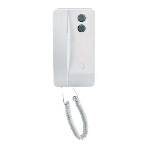
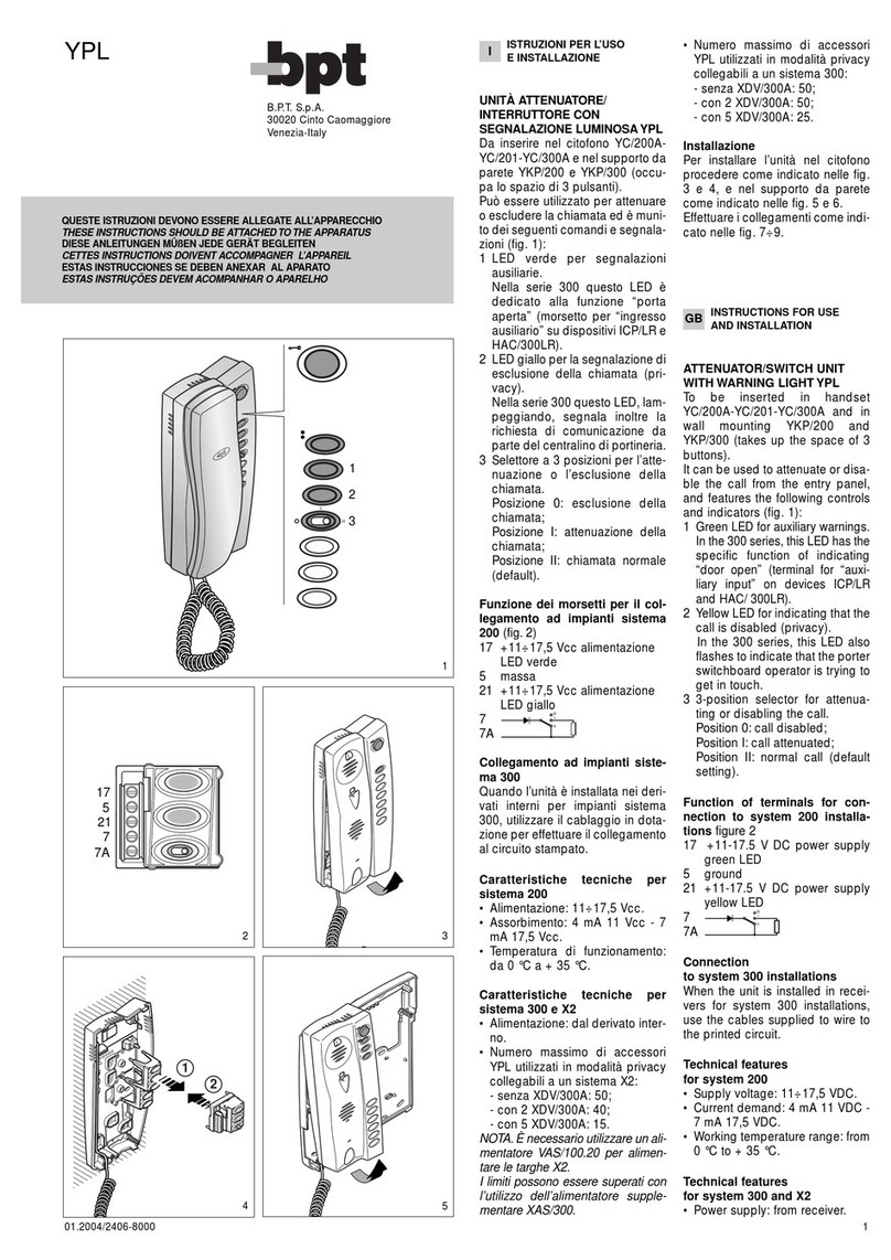
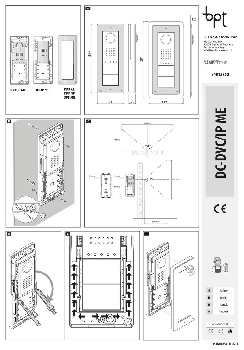
Table of contents
Other Bpt Intercom System manuals