Breas NIPPY ST+ User manual
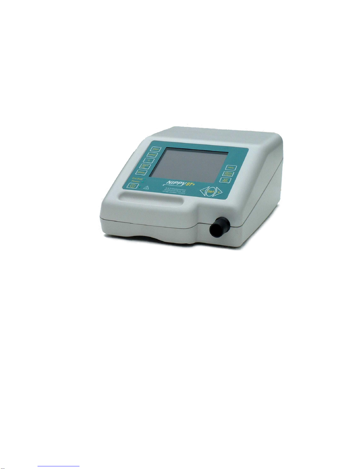
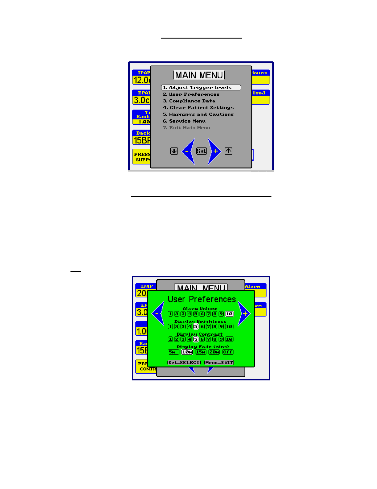
DOC 0917
INSTRUCTION MANUAL
FOR THE NIPPY ST+
POSITIVE PRESSURE
VENTILATOR
This book must be kept with the machine
Breas Medical Ltd
Unit A2, The Bridge Business Centre
Timothy’s Bridge Road
Stratford Enterprise Park
Stratford–upon-Avon,
Warwickshire. CV37 9HW
Tel: 01789 293460
www.nippyventilator.com
Version 6 November 2017


NIPPY ST+
INSTRUCTION MANUAL INDEX
Page
Introduction 1
Description 2-4
Intended Use 5
Contraindications 6
Features 7
Explanation of Controls
Fascia Buttons 8
Fascia Display 9
Outlets 10
Rear Panel Layout 10
Explanation of Symbols Used 11
Getting Started
The Main Screen 12
How to Adjust the NIPPY ST+ 12
The Menu Window 13
How to use the on-screen Menu 13
Structure of the Main Menu 14
How to use the on-screen help 15
Using Help with the Settings Locked 15
Breathing circuits and masks 16
Setting Up
Setting up the NIPPY ST+ in CPAP Mode 17
Setting up the NIPPY ST+ in Pressure Support Mode 18
Setting up the Alarms
Disconnection Alarm 19
Apnoea Alarm 19
Max Breath Rate Alarm 20
Alarm Conditions/Tests
Disconnect
Low Flow 21
Mains Fail 21
High Pressure 21
Fault 21
Sigh Function 22
Running the NIPPY ST+ on Battery Power
Battery Run Times 23
Battery Care 25-26
External battery 27
Connecting Auxiliary Equipment 28
Pneumatic Diagram 28

Specifications 29
International Standards 29
Operation Under Extreme Conditions 30
Accessories and Spares 30
Warnings and Cautions 31
Using Supplementary Oxygen 32
Maintenance
User Maintenance 33
Servicing/Warranty/Transportation 34
Factory Service / Repair 34
EMC Declaration and guidelines 35-37
Battery Run Time Test Record 38
Locking the Settings 40
Please note Breas Medical previously traded as B & D Electromedical & some photographs in
these instructions still show the name B & D Electromedical.

1
Introduction
WARNING!
NIPPY ST+ must only be used:
• For the intended treatment in accordance with this operating manual and with the
instructions given by the responsible clinical personnel.
• In accordance with the operating conditions specified in this operating manual.
• In original and unmodified shape and only with accessories specified or approved
by Breas Medical Ltd.
Every other use may lead to risk of personal injury!
CAUTION!
Read this manual thoroughly so that you completely understand how the NIPPY ST+
is operated and maintained before taking it into use, to ensure correct usage,
maximum performance and service life.
WARNING!
This device is not intended for use as a critical care ventilator, transport
ventilator or for dependent patients.

2
Description
The NIPPY ST+ is a pressure controlled, bi-level ventilator. It compresses ambient
air and delivers it to the patient through a close fitting nasal mask. The output
pressure, can be adjusted by controls on the fascia panel. The Pressure, and all
settings are displayed on a colour LCD (Liquid Crystal Display) screen.
The screen can be set to dim after a pre-set time (accessed via the user preferences
in the main menu). To restore the display, press any button once.
The basic ventilator settings can be achieved using the four buttons to the left of the
display. The three buttons to the right of the display provide access to more
advanced features and adjustments (accessed via a menu).
For greater safety and convenience the NIPPY ST+ may be equipped with an
internal battery. The ventilator is capable of recharging both the internal battery and
an external battery when running from the mains electrical supply.
There are 2 modes of ventilation:-
CPAP (Continuous Positive Airway Pressure) Constant positive
pressure is applied via the mask. No respiratory support is
given in this mode.
Pressure Support IPAP (Inspiratory positive airway pressure) and EPAP
(Expiratory positive airway pressure) are set by the
physician. The ventilator augments the patient’s
spontaneous breathing. An adjustable back-up respiratory
rate takes over in the absence of an inspiratory trigger from
the patient. Ti is limited to a maximum of 3.0 seconds and
minimum of 0.7 seconds.

3
Alarms
Power Fail If the electrical power to the ventilator is interrupted, an audible
alarm will sound. This alarm will run for 5 minutes unless cancelled with the mute
button. Once cancelled the power fail alarm will not re-activate.
Low Internal Battery When running on its optional internal battery, the alarm will
operate when the battery is almost depleted
The user cannot replace this battery. Refer to qualified technical personnel for battery
replacement.
Low External Battery When running on an external battery, the alarm will operate
when the battery is almost depleted. Machines fitted with an internal battery will
automatically switch to internal battery power without alarming.
Low Pressure A pre-set low pressure alarm is provided. If the control pressure falls
to below 50% of the set IPAP level for 10 seconds an audible and visual alarm will
operate.
High Pressure A pre-set high-pressure alarm is provided. If the pressure rises above
120% of the working pressure, an audible and visual alarm will operate after a 2
second delay.
Breathing Circuit Disconnect A disconnect alarm is provided. This is
activated by analysis of the inspiratory and expiratory flow waveform. An audible
and visual alarm will operate.
Fault The alarm may also be operated by an internal fault. In this case the fault will
be displayed on screen.
These alarms may be muted for approximately 2 minutes to allow for setting up of
the ventilator.
Low Alarm Battery An intermittent alarm (short beep) with no onscreen message
indicates a depleted mains fail alarm battery. If the ventilator has been stored for more
than a few weeks the internal battery will self discharge. In this case the alarm will stop
after the battery has recharged.
The user cannot replace this battery. Refer to qualified technical personnel if the alarm
operates when the ventilator is in daily use.

4
Estimated Tidal Volume
The estimated tidal volume is a calculated value, based on time and calibrated flow
values. The constant leak through the breathing circuit exhalation port is subtracted
from this calculation to give a reasonably accurate estimation of tidal volume. The
estimated tidal volume is displayed above the bargraph display.
Inspiratory Trigger
The NIPPY ST+ employs flow triggering, detecting the start of the patients inspiratory
effort when the flow rate exceeds the level set by the Inspiratory Trigger sensitivity.
Expiratory Trigger
The expiratory trigger is used in Pressure Support mode only. Towards the end of
inspiration, when the inspiratory flow rate drops to the baseline (standing flow caused
by exhale port leak) minus the expiratory trigger sensitivity the ventilator will cycle into
the expiratory phase.
The inspiratory and expiratory effort required to cycle the ventilator can be adjusted
via the Trigger option in the Menu.
For simplicity the trigger sensitivity is scaled 1 –10, with 1 requiring the least patient
effort and 10 requiring more patient effort.

5
Intended Use
The NIPPY ST+ is intended to provide non-invasive ventilation for non-dependent,
spontaneously breathing adult patients with respiratory insufficiency, or respiratory
failure.
The NIPPY ST+ is not intended for life support or life-sustaining applications or for
transport of critical care patients.
The NIPPY ST+ is intended for use in clinical settings (e.g., hospitals and sub-acute
care institutions) and home environments.
The NIPPY ST+ is intended for non-invasive use only.
The NIPPY ST+ shall only be used by patients who are spontaneously breathing.
The NIPPY ST+ must always be prescribed by a competent physician.
The NIPPY ST+ is intended for treatment of adult patients only.
The NIPPY ST+ is intended to be operated by qualified and trained personnel only.
IMPORTANT!
NIPPY ST+ must be prescribed by, and used only under the supervision of a
qualified physician.
This manual is only intended for clinical personnel, physicians and trained users who
require a working knowledge of the NIPPY ST+.
Alarms must be tested before use and following a change of the breathing circuit as
described in the Alarms Conditions/Tests section.
It is the clinicians responsibility to ensure the device is always used with the
appropriate breathing circuit, to ensure sufficient CO2 elimination. All care staff
should be trained to ensure that the location of this exhalation port is known and they
are aware that this must not be removed, covered or blocked at any time.
Batteries used for power fail back up must be kept in good condition and fully
charged at all times. See Battery care section of this manual.

6
Contraindications
The NIPPY ST+ is not a life support ventilator.
The use of the device may be contraindicated in patients with the following:
•Pneumothorax or pneumomediastinum
•Low blood pressure
•Cerebrospinal fluid leak, recent cranial surgery or trauma, or raised
Intercranial pressure
•Severe bullous lung disease
•Dehydration
•Risk of vomiting
•An oxygen requirement higher than achievable with 15l/min of entrained low
pressure oxygen and the prescribed ventilation settings
Adverse effects
Patients should report any new or unusual chest pain, severe headache or increased
breathlessness or increased day time sleepiness to a clinician immediately.
The following side effects may be experienced during the treatment with non invasive
ventilation:
•Nasal, mouth or throat dryness
•Bloating
•Ear or sinus discomfort
•Eye irritation from mask leak

7
Features
1. Comprehensive alarms with mute facility
2. User friendly intuitive user interface
3. Easily understood alarm messages displayed onscreen
4. 2 modes of ventilation
5. Universal mains input, operates anywhere in the world without transformers
6. Optional internal battery
7. Adjustable flow triggers with trigger indicators
8. Large, colour LCD display, clearly shows all settings
9. 28 days stored, On-screen compliance data
10. Comprehensive event log stores all adjustments, settings, alarm events
and user interventions, for download to PC.
11. Fast trigger response
12. Minimal maintenance requirement
13. Twelve months parts and labour warranty
14. Auto switching to back-up battery
15. Automatic service reminder

8
Explanation of controls
Clear
1
2
3
4
5
6
789
10
11
12
13
14
15
Fascia Buttons
1. IPAP - Selects the Inspiratory Positive Airway Pressure
adjustment (scaled in cm H2O). Value is displayed on
screen adjacent to the switch.
2. EPAP - Selects the Expiratory Positive Airway Pressure
adjustment (scaled in cm H2O). Value is displayed on
screen adjacent to the switch.
3. Ti - Selects the inspiratory time adjustment (scaled in
Seconds). Value is displayed on screen adjacent to the
switch.
4. Back up - Selects the Back-up Rate adjustment (scaled in Breaths
Per Minute). Value is displayed on screen adjacent to
the switch.
5. Mode - Displays the mode selection screen
6. - Starts and Stops the ventilator
7. ◄- - Decrements the selected parameter or moves the
selection bar down the menu.
8. Set - Selects the current menu function displayed by the
selection bar
9. +► - Increments the selected parameter or moves the
selection bar up the menu
10. Mute - Silences the alarm for 2 minutes. Press and hold for 2
seconds to cancel alarm mute.
11. Menu - Displays the menu screen
12. Help - Displays context sensitive help messages.
13. Ext. Batt - Indicates that ventilator is running on battery power.
This may be internal or external
14. Power - Indicates that external power is connected.
Ext Batt OFF and Power ON = Battery charging
15. Start - Indicates that the ventilator is running.

9
Fascia Display
1
234
5
6
7
8
9
11
12
10
4
4
13
1. Mode - Displays current mode of ventilation.
2. Pressure Display - Indicates airway pressure (scaled in cm H2O).
Changes colour to red in under / over pressure
alarm condition.
3. Rate Display - Indicates patient breath rate (scaled in Breaths Per
Minute).
4. Volume Display - Indicates estimated inspiratory tidal volume (scaled
in millilitres).
5. Settings locked symbol - This symbol shows that the settings are locked.
6. Alarm Muted symbol - This symbol shows that the audible alarm has been
temporarily silenced.
7. I Trigger indicator - “Flashes” each time the inspiratory cycle is initiated
by the patient.
8. E trigger indicator - “Flashes” each time the expiratory cycle is initiated
by the patient.
9. External battery - Indicates external battery state of charge, when
connected. Red when Discharged.
10. Internal battery - Indicates internal battery state of charge. If fitted.
Red when Discharged.
11. Total Hours - Shows total machine running time.
Used to determine service intervals
12. Hours Used - Shows total hours of use. (Compliance Hours)
13. Service Reminder - Major service due

10
Ventilator Outlets
1
1. Outlet - Main Air Outlet to breathing circuit
Rear Panel Layout
1. Aux. Power - 24 Volt connection for external battery. Connect only
recommended battery, part no 0910.
2. RS232 Port - For connection to remote alarm or personal
computer. Isolated to 1500 Volts.
3. Power Inlet - Input mains power connector. Double fused and
fitted with connector retaining clip.
0086
100 - 240V
0.4 - 1.0 Amperes
47 - 63Hz
Fuse 2 x T1.6A SN
RS 232
Cooling Vent
1
2
3

11
Explanation of Symbols used on NIPPY ST+ and
Accessories
- Type B Applied parts to EN 60601-1
- Alternating Current
- Direct Current
T- Time Delay Fuse
SN - Serial Number
- Date of Manufacture
- Attention. Consult Accompanying Documents
- Switch ON /OFF
+► - Increase Button
◄- - Decrease Button
- Locked / Unlocked, Purple = total lock, Black = settings locked
- Alarm Muted
- Battery charged
- Battery Discharged
- Service Reminder
- Dispose of in Line with Local Authority Guidelines
- Recycle
- Batch code

12
Getting Started
To Switch On
Place the NIPPY ST+ on a clean, smooth, hard surface. (NOT carpet)
Connect the power lead to the mains power connector on the rear panel. Plug into
the mains power supply.
Press the Start/Stop button.
To Switch Off
Press the Start/Stop button. The “Switch Ventilator Off” message will appear
onscreen. Press the Start/Stop button again after 2 seconds. There must be a delay
of 2 seconds before each push, to prevent accidental operation.
The Main Screen
The Main Screen is divided into 3 areas
The left-hand side shows the basic ventilator settings, IPAP, EPAP, Ti, BACK-UP,
and Mode, adjacent to its setting button.
The centre section shows the airway pressure, estimated tidal volume and breath
rate.
The right-hand side shows the Total hours, hours used and symbols for alarm mute
and locked settings.
Clear
How to adjust the NIPPY ST+
Select the desired parameter with the relevant button.
The reading adjacent to the button will be highlighted by a purple flashing box.
Alter it with the ◄-or +► buttons.
When you have finished, move on to the next adjustment or wait a couple of seconds
for the flashing box to disappear.
E.g. Press IPAP.
IPAP setting will be surrounded by a purple flashing box.
Press +► to increase the pressure setting.

13
The Menu Window
The Main Menu gives access to further adjustments and allows you to view
information relating to the ventilator usage.
How to use the on-screen menu
Press the MENU button. The menu window will be displayed in front of the main
screen.
Move the selection bar up or down the menu with the ◄-or +► buttons to highlight
the desired function and press the SET button.
Follow the on-screen instruction at the bottom of the window
Press MENU at any time to exit and return to the main screen.
Eg.
Press MENU.
Press ◄-button to move the selection bar over “User Preferences”.
Press SET. Press SET again to move the ◄-and +► symbols either side of
“Display Contrast”
Press +► to increase contrast - Press MENU to exit.

14
Structure of the Main Menu
1. Adjust Trigger I Trig View / Adjust
E Trig View / Adjust
2. User Preferences
User Preferences Alarm Volume View / Adjust
Display Brightness View / Adjust
Display Contrast View / Adjust
Display Dimming View / Adjust
(Sets time in minutes until display dims, to night time level)
Disconnection Alarm View / Adjust
Apnoea Alarm View / Adjust
BPM Alarm View / Adjust
Sigh Settings View / Adjust
3. Compliance Data Total Hours View only
Compliance Hours View only
Average Daily Use View Only
Use + or –button to scroll through the data.
Press and hold + and –buttons to reset compliance data
4. Clear Patient Settings Resets machine to default settings and clears the
compliance data, ready for a new patient.
5. Warnings & Cautions Safety information View only
6. Service Menu Service Information Restricted Access

15
How to use the On-screen Help
Press the HELP button at any time for a list of help topics. Follow the simple on-
screen instructions.
Press HELP again to exit.
If during setting up, you require a description of a particular parameter, select it then
press HELP. Press HELP again to clear.
Using Help with settings locked
When the settings have been locked, help is limited to a list of more common
problems that may arise during use and advice on how to deal with them.
Follow the on-screen instructions

16
Breathing Circuits
Breathing circuits to be assembled in the order A-B-C-D from the ventilator end.
The NIPPY ST+ uses a single limb circuit. Always use a ventilated mask.
Part Number 0792
Breathing circuit volume = 570 ml including filter.
Table of contents
Other Breas Medical Equipment manuals

Breas
Breas Z2 Auto User manual

Breas
Breas iSleep 20+ User manual

Breas
Breas Vivo 1 User manual

Breas
Breas Vivo 45 LS User manual

Breas
Breas Vivo 65 User manual

Breas
Breas Vivo 45 LS User manual

Breas
Breas Vivo 50 User manual

Breas
Breas Vivo 50 User manual

Breas
Breas NIPPY Clearway User manual

Breas
Breas Clearway 2 User manual

Breas
Breas Vivo30 User manual

Breas
Breas Vivo 45 LS User manual

Breas
Breas Vivo 50 User manual

Breas
Breas Vivo 3 User manual

Breas
Breas Vivo 45 User manual

Breas
Breas Vivo 40 User manual

Breas
Breas NIPPY Clearway User manual

Breas
Breas Vivo 65 User manual

Breas
Breas Clearway 2 User manual

Breas
Breas PV 102+ User manual