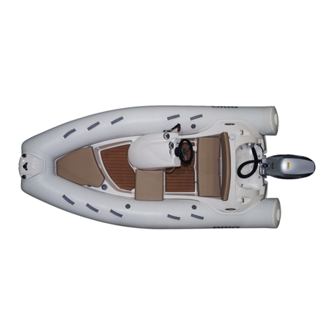
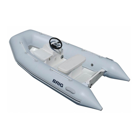
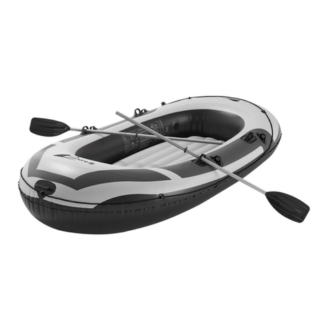
BRIG Eagle Series User manual

OWNER'S MANUAL
English
2378C.01
H* – boat tube is made of HYPALON (Du Pont registered trademark) coated fabrics.
SERIE:
"EAGLE"
MODEL:
Eagle 3.5
complete set:
E3.5 E3.5H*
Design category (2013/53/EU): C
ISO6185: Category VII

— 2 — BRIG
DANGER LEVELS
INTRODUCTION
IDENTIFICATION PLATE
SAFETY REGULATIONS
BEAUFORT W ind Scale
BOAT DESIGN CATEGORIES
REMEMBER FIRE DANGER ALWAYS
TECHNICAL SPECIFICATIONS
COMPLETE SET
BOAT DESIGN
LOCATION OF THE MAIN SYSTEMS
BUOYANCY TUBE
TUBE INFLATION
STEERING CONSOLE
SW ITCH PANEL AND FUSE BOX
WIRING DIAGRAM
BATTERY INSTALLATION
FUEL SYSTEM
DRAIN SYSTEM
CREW LIMIT
TOWING
MOORING
BOAT TRAILERING
THE MAINE DIMENSIONS
MAINTENANCE
OPERATING REGULATIONS
W ARNING SIGNS AND LABELS
5
5
6
7
8
8
9
1 0
1 1
1 2
1 4
1 5
1 6
1 7
1 8
1 9
2 0
2 0
2 2
2 4
2 5
2 6
2 7
2 8
2 9
3 0
3 5
CONTENTS:

— 3 —
Model EAGLE 3.5 - 2020 237 8C.0 1
For you safety and for the validity of the guarantee expert and authorised personnel
must install the motor and inspect and check the systems. All onboard systems must
be completed and inspected.
CHECK, THAT THE CHECKS HAVE BEEN MADE AND THAT THE PLANTS HAVE
BEEN COMPLETED BEFORE DELYVERY.
BRIG Ltd declines any responsibility for systems and accessories that hav e not
been installed and checked by expert and authorised personnel.
The manual and all its enclosures should be stored carefully, and the manual should
always be kept aboard. If the craft is resold, the manual and all its enclosures must
be handed over to the new owner.

— 4 — BRIG
CE Certification and Main Features
The CE marking indicates that the inflatable boat meets the requirements of the Recreational
Craft Directive 2013/53/EU
Certifying Body:
INTERNATIONAL MARINE CERTIFICATION INSTITUTE
Rue Abbe Cuypers 3 / B-1040Bruxelles / Belgique
Notified Body : 0609
www.imci.org
Name of Manufacture:
BRIG Ltd.
Lozovskaya 88, Dergachy 62303
Kharkovskaya obl.
UKRAINE
www.brigboats.com

— 5 —
Model EAGLE 3.5 - 2020 237 8C.0 1
INTRODUCTION.
This manual was written to help you to use your boat safely. It contains information on the boat, it s equipment
(supplied or installed),operation an d maintenance.
DANGER LEVELS.
The manual contains warnings, identified as follows:
A note like this indicates that there is serious risk, that is likely to cause death or permanent
serious injury, if appropriate precautions are not taken.
A note like this indicates the existence of risk that may cause death or injury, if appropriate
precautions are not taken.
A note like this indicates reference to the application of safety or environmental protection
practices,or draws attention to unsafe behaviour that might cause injury to persones or damage
to the craft, its components or the environment.
Before using your boat, read this MANUAL carefully and ensure that you have
understood all the procedures it describes. Before taking command of your boat, be
sure to have acquired experience and confidence in its operation.

— 6 — BRIG
It is fundamental for the plates to be aboard the boat, since they are only f orm of
recognition and identification. Without them the boat does not comply with the
legislation in effect. The plates must never be removed. Any tampering or removal not
authorised by the manufacturer is the full responsibility of the owner.
Plate with identification number:
UA-QRK12345A000
IDENTIFICATION PLATE.
Builder's Plate:
Maximum propulsion
power rating
Boat Design Categories
according to
Directive 2013/53/EU
The rated tube
pres sure value
Passengers capacity
(75kg each)
Manufacturer’s recommended maximum load, including the
mass of the outboard engine(s) but excluding the mass of
the contents of fixed fuel and water tanks when full
Eagle 3.5
VII
C
29.5 40 4
640 1410
3

— 7 —
Model EAGLE 3.5 - 2020 237 8C.0 1
SAFETY REGULATIONS.
This manual contains recommendations and basic rules of conduct for using the boat in complete safety.Although
it is not possible to offer safety information for all potential situations, in general it is recomm ended that you :
Regularly check which safety requirements are in force.
Maintain the boat and the onboard plants in optimum condition.
Have the boat inspected by the dealer where it was purchased or by an authorised
mechanic at least once every year for your own safety and for maintaining the guarantee.
Always check weather and seagoing conditions before setting out.
For safe navigation, compare the design category of your boat with the table below.
W hen the tank is installed by the yard, the plant is prepared with a ground plait. The
installation of the motor MUST FORESEE A PLAINT CONNECTION to the boat ground plait.
Failure to connect (or failed maintenance) can result in the tank perforating leading to a
serious risk of fire / explosion caused by leaking fuel.
Max number of transportable persones is referred to an established weight of 75 kg per
person (ISO 6185), so always make reference to total maximum transportable weight.
The max weight of the installable motors indicates the maximum overall weight applicable
on the stern board, including any emergency motors. NEVER exceed the stated value.

— 8 — BRIG
BEAUFORT Wind Scale and Corresponding State of the Sea, After Few Hours of Wind, Away From the Coast.
Boat Design Categories (Directive 2013/53/EU):
NOTE: The significant wave height is the mean height of the highest one-third of the waves, which approximately corresponds
to the wave height estimated by an experienced observer. Some waves will be double this height.
State of the sea
Fo rce De nominati o n Knots K m / h m / s e c and wave height in meters
0 Calm <1 <1 0-0.2 Calm 0
1 Light Air 1-3 1-5 0.3- 1.5 Calm 0
2 Light Breeze 4-6 6- 11 1.6- 3.3 Almost calm 0.2
3 Gentle Breeze 7- 10 12-19 3.4- 5.4 Almost calm 0.2
4 Moderate Breeze 11-16 20-28 5.5- 7.9 Small waves 0.5
5 Strong Breeze 17-21 29-38 8.0-10.7 Large waves 1.25
6 Fresh W ind 22-27 39-49 10.8-13.8 Large waves 2.0
7 Strong W ind 28-33 50-61 13.9-17.1 Ver y large waves 2.5
8 Gale 34-40 62-74 17.2-20.7 Rough sea 4
9 Strong Gale 41-47 75-88 20.8-24.4 Very rough sea 6
1 0 Storm 48- 55 89- 10 2 24. 5- 28. 4 H ea vy 9
1 1 Violent Storm 56-63 103- 117 28.5-32.6 Very heavy 1 4
1 2 Hur ricane 64 and over 118 and over 32.7and over Stormy 14 and over
Design category
"A" - "Ocean"
"B" - "Offshore"
"C"- "Inshore"
"D" - "Sheltered waters"
Wind force
(Beaufor t scale)
exceeding 8
up to,and including, 8
up to,and including, 6
up to,and including, 4
Significant wav e height
exceeding 4
up to,and including, 4
up to,and including, 2
up to,and including, 0.3

— 9 —
Model EAGLE 3.5 - 2020 237 8C.0 1
ALWAYS REMEMBER ABOUT FIRE DANGER.
Fire may be caused by:
Crew negligence when smoking, the presence aboard of flammable liquids, electrical contacts, propulsion motor, errors in fueling, or if
maintenance has not been performed as required.
Once again, it is important that the crew behave correctly and that the boat is kept in order to avoid serious damage to it and to persons.
However, if a fire does occur aboard, stop motor, disconnect the batteries immediately, check to see if it is an electrical component or any case
a small-scale fire that does not involve flammable liquids, in which case use a suitable fire extinguisher to try and put the fire out completely.
Easily flammable products must not be kept aboard.
BATTERY: the battery may cause sparks or explosions. It must be stored in an appropriate
container, easily reached and well aired, AW AY FROM FUEL OR INFLAMMABLE PRODUCTS.
Periodically check that the clips are tight and protect them with appropriate insulation in
order to prevent sparks or the spread of current.
Extinguisher or any other fire-fighting equipment must not be kept in compartments with
key lock, but in easily accessible and clearly indicated locations.
Extinguisher or any other fire-fighting equipment should be checked periodically and
replaced with the same or superior types if expired or inefficient.
Equip the boat with fire-fighting equipment before launch and use.

— 10 — BRIG
TECNICAL SPECIFICATIONS.
The basic parameters and dimensions of the boat Eagle 3.5 comply with the data specified in the following table.
All dimensions measurments indicated have a tolerance of +/- 3%, weight measurments indicated have a tolerance of +/- 5%.
* When the boat is fitted with an engine with maximum recommended power it must be use with extreme care.
This application is directed at experienced users using their boats for very specific purposes.
Pa r am et er Eagle 3.5
Length (without engine)
Beam
Height without engine
Inflatable tube diameter, max.
Cockpit dimensions:
- length
- width
Deadrise angle on transom
Deadrise angle in middle section
Transom height
Number of independent air-tight chambers
Nominal air pressure in the tube
Passengers capacity
Rec ommended engine power
Maximum engine power*
Maximum engine weight (including controls and battery)
Engine shaft length
Built-in fuel tank capacity
Max weight of empty boat (without fuel and engine)
Maximum load capacity of empty boat(ISO method)
Displacement in Light Craft Condition (LCC)
Maximum total load (ML)
Maximum recommended load (including weight of the
max engine, passengers and cargo onboard, but excluding the
mass of the contents of fixed fuel tank when full)
Loaded displacement mass
3.50 m
1.78 m
1.13m
0.46 m
2.18 m
0.85 m
15°
17°
510mm
3
0.15bar / 2.2 psi
4
30HP / 22.1kW
40HP / 29.5kW
145kg
20" (Long)
33L
190kg
670kg
340kg
520kg
640kg
860kg

— 11 —
Model EAGLE 3.5 - 2020 237 8C.0 1
COMPLETE SET.
Note.
Perfection of the design and improvement of quality of our products is the fundamental production policy of our company.
Therefore, alternations may be made to the complete set (and as the components become available).
In the table shows the maximum possible complete set, which may differ from your boat.
1Rigid inflatable boat pc. 1
2Foot pump pc. 1
3Pa dd l e pc s . 2
4Bag pc . 1
5Own er ' s man ua l pc. 1
6Fu el s y st em pc. 1
7Inbuilt fuel tank pc. 1 (33L)
8St eer ing co nso le pc. 1
Steering console equipments:
9 Steering system pc. 1
1 0 Steering wheel pc. 1
1 1 Steering cable pc. 1
1 2 Switches of electrical equipment pcs . 4
1 3 Speedometer pc . 1
1 4 Tachometer pc . 1
1 5 Socket 12V+USB pc. 1
1 6 Fr ont step plate with navigation lights pc. 1
1 7 Front cusions set 1
1 8 Stern cusion with soft backr est pc. 1
1 9 Masthead lig ht ( whit e) pc. 1
2 0 Batt ery container pc. 1
2 1 Batt ery di sconnector pc. 1
2 2 Automatic drain bilge pump pc. 1
2 3 Ov erall cover pc. 1
2 4 Valv e cap pressure gauge pc. 1
2 5 Lifting slings set set 1
2 6 SeaDek set set 1
N o D es c r ip t i o n Unit Eagle 3.5

— 12 — BRIG
BOAT DESIGN.
Fig.1
1
2
3
4
5 6 78
10
9
11 12 13
14
15
16
17 18 19
10

— 13 —
Model EAGLE 3.5 - 2020 237 8C.0 1
DESCRIPTION:
1 — Fiberglass plastic hull.
2 — Reinforced buoyancy tube.
3 — Rubbing strake.
4 — Towing bow eye.
5 — Front step plate.
6 — Navigation lights (red and green).
7 — Steering console
8 — Steering wheel
9 — Masthead navigation light (white).
1 0 — Lifting eyes
1 1 — Front removable cushion.
1 2 — Safety handles.
1 3 — Hatch
1 4 — Side cursion.
1 5 — The neck of the fuel tank.
1 6 — Air fill valve
1 7 — Stern cushion with backrest.
1 8 — Rear mooring cleats.
1 9 — Handles.
2 0 — Bilge pump nozzle
2 1 — Cockpit drain sockets.
2 2 — Outlet for steering cable
2 3 — Drain plug
2 4 — Plate with HIN code
21
22
23
24
Fig.1
20

— 14 — BRIG
LOCATION OF THE MAIN SYSTEMS:
1 — Bow loc ker
2 — Air fill valve
3 — The neck of the fuel tank
4 — Fuel level sensor
5 — Fuel tank (33L)
6 — Fuse box
7 — Stern hatch
8 — Main switch with fuse (port side)
9 — B at t er y
1 0 — Fitting of a fuel tank ventilation
1 1 — Cockpit drain sockets
1 2 — Cockpit drain hoses
1 3 — Cockpit drain valves
1 4 — Automatic bilge pump
1
2
3
6 7 8 10
5 11 12 14 13 9
4
Fig.2
11

— 15 —
Model EAGLE 3.5 - 2020 237 8C.0 1
5 6 8 7
4 1 2 3
Fig.3
The boat buoyancy tube has U-shaped form. The tube is separated by
means of inner elastic partitions into 3 chambers of a similar volume, each
being provided with an air fill valve.
The air fill valve is intended for:
— filling the compartment with air from a standart pump or filling system
and maintaining pressure in the tube for prolonged time,
— adjustable drop of pressure in compartment.
The air fill valve is designed as a tab-type non-return valve and consists
of the following components (Fig. 3):
— housing (1);
— cup (2) with strap (3);
— washer with gasket (4);
— nut (5);
— spindle (6) with spring (7) and cup diaphragm (8).
Also there are the following elements fitted on the tube (Fig. 1):
— doubled rubbing strake;
— safety handles;
— bow step-plate with navigation lights;
— tube polyester ends with two antiskid steps each.
The sequence of filling the pipe with air:
1. Fill one of the compartments with air to a pressure of approximately 0.1
bar.
2. Fill the other compartments sequentially with air to a pressure of
approximately 0.1 bar(1.45psi).
3. Only after that, bring the air pressure in each tube compartment to the
nominal (0.15 bar/2.2psi).
BUOYANCY TUBE.
The rated pressure value is 0.15 bar (2.2 psi).
If the tube pressure more than nominal, deflate the tube slightly. Boat exploitation with
board pressure more than nominal decreases boat service life.
Do not use compressors and/or other types of inflating equipments not approved by the
boat builder.
Check the tube pressure before every navigation.

— 16 — BRIG
TUBE INFLATION.
Before inflation of compartment it's necessary to set all valves in operating condition. In order to switch valve to
operating condition, just press spindle 6 (look before Fig. D3) with your finger and turn it clockwise untill it is
fixed. If it isn't possible the valve is in operating condition already.
Fill the tube compartments with air using the pump from the complete set. First fill two rear compartments, then
bow compartment. Thereat, do not bring the pressure up to its operating value (the tube will be completely
straigh tened) .
Then fill the bow compartment with air up to the rated pressure.
The rated pressure value is 0.15 bar (2.2 psi)
On completion of filling close the valves with caps.
In order to discharge air from the compartments, open the valves (just press spindle with your finger and turn it
anticlockwise till it is fixed).
Board air chambers are hermetical if they keep own form during 8 hours. In this case:
– primary pressure has to be nominal;
– input valves openings have to be tightly closed by caps.
The rated pressure value is 0.15 bar (2.2 psi).
If the tube pressure more than nominal, deflate the tube slightly. Boat exploitation with
board pressure more than nominal decreases boat service life.
Do not use compressors and/or other types of inflating equipments not approved by the
boat builder.
Check the tube pressure before every navigation.

— 17 —
Model EAGLE 3.5 - 2020 237 8C.0 1
STEERING CONSOLE.
Steering console is located in the central part of the boat. The console consists of
the following components (Fig. 4):
— console body (1) is installed on the built-in the boat deck console base
— windscreen (2);
— instrument placement (3) (speedometer, fuel gauge, chartplotter, etc.);
— hatch (4).
— steering wheel (5);
— switch panel (6);
— socket 12V + USB (7);
— fuse box (inside the body of the console, not shown);
Fig.4
1
2
4
6
5
7
3

— 18 — BRIG
SWITCH PANEL AND FUSE BOX
The purpose of the switches(Fig.5):
1 - turning on / off navigation lights (red and green)
2 - turning on / off anchor light (white all-round)
3 - turning on / off the bilge pump in automatic mode
4 - turning on / off the bilge pump in manual mode
Access to the fuse box - through the hatch on the console.
1 - fuse is used as a backup
2 - fuse is used for navigation lights
3 - fuse is used for anchor light
4 - fuse is used for the bilge pump
5 - fuse is used as a backup
6 - fuse is used for sockets 12V and USB
Always keep a spare set the
fuse in an easily-accessible
location.
Always check the fuse. Burning
red LED display on the fuse box
warns of faulty fuse
2336.13
4
5
6
1
2
3
SWITCH PANEL
FUSE BOX
1
2
3
4
5
6
Fig.5
1 2 3 4

— 19 —
Model EAGLE 3.5 - 2020 237 8C.0 1
steering console
9
10
8
5
fuel tank
12
13
14
Fig.6
stern locker
rod
1
4
2
67
3
bow plate
11
DESCRIPTION:
1 — Battery (provided on the market).
2 — Battery disconnector with fuse.
3 — Outboard m otor (provided on th e market).
4 — Bi lg e pu mp.
5 — Anchore light (white).
6 — Port light (red).
7 — Starboard light (g ree n).
8 — Fuel level gauge.
9 — fue l g au ge .
1 0 — S pe e do me t e r .
1 1 — T a c h o m e t e r .
1 2 — Meter lamp and navigation lights switch with 5A safety device.
1 3 — Hull drain pump "MANUAL" / "AUTO" switch with 10A safety device.
1 4 — Anchore light switch with 5A safety device.
WIRING DIAGRAM.
Any modification, repair and planned
maintenance may be made by authorized
representative specialists only.
Do not touch the electrical equipment
with wet hands.
When leaving the boat, remember
to disconnect the batteries.

— 20 — BRIG
Fuel system consists of the following components (Fig. 7):
– built-in fuel tank 33L (1) with level sensor
– fuel gauge (2)
– fuel line (from fuel fill neck to fuel tank) (3)
– fuel fill neck (4)
– fuel tank ventilation line (5) with ventilation fitting (6)
– carbon canister (7) (may not be installed by the manufacturer)
– fuel line to the engine (8)
– fuel filter (9) (not installed by the manufacturer)
– fuel level sensor (10)
–
inspection hatches (11)
FUEL SYSTEM.
BATTERY INSTALLATION.
In order to install the storage battery, perform next operations:
— open door of the stern compartment;
— install the storage battery into the battery container;
— connect the battery terminals with motor battery cord and
battery disconnector;
— please, check efficiency of the electric equipment.
Before installation your storage battery
read the BATTERY MANUAL carefully
and ensure that you have understood all
the described procedures.
1
2
3 4 5
6
7
8 9
10
11
Fig.7
Other manuals for Eagle Series
1
This manual suits for next models
1
Table of contents
Other BRIG Boat manuals

BRIG
BRIG EAGLE E780 2013 User manual

BRIG
BRIG FALCON F330L User manual

BRIG
BRIG Eagle 8 User manual

BRIG
BRIG FALCON Series User manual

BRIG
BRIG Eagle 6 User manual

BRIG
BRIG EAGLE E780 User manual

BRIG
BRIG E480 User manual

BRIG
BRIG E340 User manual
BRIG
BRIG F275 User manual

BRIG
BRIG FALCON F400 DELUXE User manual

BRIG
BRIG Eagle 6.7 User manual

BRIG
BRIG Eagle 5 User manual

BRIG
BRIG NAVIGATOR Series User manual

BRIG
BRIG NAVIGATOR N485 User manual

BRIG
BRIG HD410 User manual

BRIG
BRIG N350 User manual

BRIG
BRIG FALCON User manual

BRIG
BRIG NAVIGATOR Series User manual
BRIG
BRIG NAVIGATOR 26 User manual

BRIG
BRIG Eagle Series User manual