BRIG HD410 User manual

INFLATABLE
HEAVY-DUTY BOAT
"BRIG"
User's manual
2359.01
Design category (94/25/EC): C
ISO6185-3: Category VII

–2–
INTRODUCTION
The "BRIG" inflatable heavy-duty boat, hereinafter referred to as the "Boat", was designed in two modifications HD410 and HD460 by the "BRIG"
Company basing on the principal provisions of International Organization for Standardization ISO 6185 "Plastomer and Elastomer Inflatable Boats".
1. PURPOSE
The "BRIG" Boats intended for the use on vessels, water areas belonging to ports and sea coastal zones as a heavy-duty boat, patrol
boat and for other professional purposes.
2. SPECIFICATIONS
The basic parameters and dimensions of the "BRIG" boat comply with the data specified in Table 1. Table 1
No. MODEL HD410 HD460
1Overall dimensions:
-maximum length, m 4.1 4.6
-maximum width, m 1.95 1.95
-maximum height, m 1.6 1.6
2Inflatable balloon diameter, m 0.5 0.5
3Cockpit dimensions:
-maximum length, m 3.0 3.4
-maximum width, m 0.95 0.95
4Deadrise angle at transom, degrees 10 10
5Deadrise angle in middle section, degrees 20 20
6Number of independent air-tight compartments, pcs 5+1 5+1
7Maximum passengers capacity, men 710
8Maximum weight-carrying capacity, kg 800 1000
9Maximum engine power, HP 40 50
10 Recommended engine power, HP 25 30
11 Transom height, mm 510 510
12 Total weight of boat without engine, kg 99 106
13 Rated excess pressure in balloon, Bar 0.15 0.15
14 Minimum excess pressure in balloon, Bar 0.1 0.1
15 Maximum excess pressure in balloon, Bar 0.22 0.22
16 Range of operating temperatures, °C from -30 to +65

–3–
2359.01 HD Series
3. COMPLETE DELIVERY SET
The "BRIG" Boat is provided as package, as specified in Table 2. Table 2
Quantity Package No.
No. DESCRIPTION
HD410 HD460
1Inflatable boat 1 1 1
2Inflatable keel 1 1 1
Rigid boarding:
3boarding segment 5 5 2
4lateral beam (coverage) 2 2 1
5removable stop 4 4 2
6Rigid seat (thwart) 3 3 2
7Foot-operated pump with hose 1 1 2
8Paddle 2 2 1
9Towing line, 15 m 1 1 2
10 Set of spare parts and repair tools in package: 2
–water discharge valve bonnet 1 1
–water discharge valve sealing ring 1 1
–cloth for repair 250x350 mm
–polyurethane glue (set) 100g
The type, size and weight of packages is specified in Table 3. Table 3
Package Overall dimensions, mm Weight, kg
No. Type of package
HD410 HD460 HD410 HD460
1cover 2000x800x400 2000x800x450 65 85
2cover 1200õ650õ200 1300õ750õ200 40 45

–4–
4. BOAT DESIGN
In the base plane projection the Boat is of U-shaped configuration (Fig.1). The body of the Boat consists of inflatable sides (balloons)
interconnected by means of a bottom part and pasted in between transom sides. The balloon is separated by means of inner elastic
partitions into five independent compartments of a similar volume, each being provided with a fill valve.
Pasted onto Boat sides are a lifeline stanchions, side towing knots, attachment points for suspension of the Boat on hooks, thwart fixing
brackets and inwale. The bow towing knot is attached at the joint of the balloon and the bottom parts.
In the central plane projection the Boat has an elevated forebody (an average elevation angle is 12 degrees).
In order to improve the seagoing ability, the Boat is furnished with a inflatable keel which imparts deadrise to the bottom (20 degrees
in the middle section). To improve stability of the Boat, the line of connection of the bottom to the sides is located above the lower point
of the side diameter.
The pasted-in transom possesses an adequate strength for an outboard engine of marine modification to be attached. Provided on
the transom are lacing eyes for towing arrangement. The transom design provides a special place for outboard engine mounting and two
water discharge valves.
The Boat is furnished with a separable rigid boarding which serves to enhance the strength of the Boat.
Provided for Boat lifting and lowering are knots. The knots (attachment points) are pasted onto the sides of the Boat.
The Boat is furnished with paddles intended for the use in case of engine failure, to maintain the windward position of the Boat and
when mooring. The paddles are fixed on the sides of the Boat beneath the thwart.
Fixed with a sag to the sides along the entire perimeter of the Boat is lifeline intended to maintain men afloat and facilitate their climbing
into the Boat from water.
Provided on each side of the Boat are two carrying handles.
The elastic inwale serves to protect the sides against wearing out by abrasion and striking against floating objects.
The rigid seat (thwart) is fixed to elastic brackets arranged on the internal side of the balloon along the sides of the Boat.
All the above-mentioned design components of the Boat are shown in Fig.1.

–5–
2359.01 HD Series
116 815
13 12 17
1 2 11 17 310 214 4
7
4
6
5
9
18
1 – inflatable balloon; 10 –rowlock;
2 – elastic partitions; 11 –solid rigid separable boarding;
3 – fillvalve; 12 –lifelinestanchion;
4 – transom; 13 –lifeline;
5 – water discharge valve; 14 –rigidseat(thwart);
6 – outboard engine mounting point; 15 –inwale;
7 – holes for towing arrangement; 16 –lateraltowing knot;
8 – elastic bottom; 17 –attachment points for suspension of Boat on hooks;
9 – bow towing knot; 18 –strengthening strips on bottom surface of Boat.
Fig.1

–6–
5. DESIGN AND OPERATION OF BOAT COMPONENTS AND ASSEMBLIES
5.1. ENGINE UNIT
The design of the Boat provides accommodation of an outboard engine with an elongated deadwood (with the transom height being 510 mm). The engine
is fixed on the transom in a place specially provided for the purpose.
The fuel tank is arranged in a space specially provided on the boarding close to the transom. The tank is attached to the boarding by means of clamps.
5.2. RIGID BOARDING
The rigid boarding comprises the following components (see Fig.2):
– five boarding segments 1-5;
– four removable stops 6;
– two lateral beams (coverages) 7.
The lateral beams 7 serve to protect the boarding segments against relative misalignment when the crew members move across the boarding.
The upper surface of the boarding segments has a special non-slip coating.
Fig.2
547 6 3 2 1

–7–
2359.01 HD Series
5.3. VALVES
The Boat design provides for two types of valves described below.
5.3.1.Inflation/deflation valve.
The inflation/deflation valve is installed in each compartment of the balloon and consists of (fig.3):
- housing 1,
- cup 2 with strap 3,
- washer with gasket 4,
- nut 5,
- spindle 6 with spring 7 and cup diaphragm 8.
Before inflation of compartment it’s necessary to set all valves in operating condition. In order to switch
valve to operating condition, just press spindle 6 with your finger and turn it clockwise until it is fixed.
In order to deflate the compartment, just press spindle 6 with your finger and turn it counterclockwise
to switch the valve in position “OPEN”.
5.3.2. One way drain valve.
Provided on the Boat transom are two valves intended for the following:
- partial drainage of the Boat (down to the water-line level) being stationary or moving under
displacement conditions.
- complete drainage (to 95%) of the Boat moving under gliding conditions.
The one way drain valve (fig.4) consists of:
- body 1;
- nut 2;
- cup 3 with holding cord 6;
- petal 4;
- seal ring 5.
Fig.3
3
7
6
1
5
2
8
4
Fig.4
4
6
3
5
2
1

–8–
Fig.6
5.4. SUSPENSION OF BOAT ON HOOKS
The arrangement of suspension of Boat HD410 and HD460 is
identical. Provided with the purpose of Boat suspension are six
suspension rings (three rings on each side, Fig.5).
If necessary, the Boat may be fixed by means of eight hooks: six
hooks - to the rings and two hooks - to the transom lacing eyes.
The Boat with load
The Boat without load
6. ASSEMBLY PROCEDURE
In order to set the Boat in the running order, perform the
following operations:
6.1.Arrange the Boat on an even surface.
6.2.Set all valves in the operation condition (look before).
6.3.Lay out the inflatable keel with the valve facing upwards and
insert it into the pockets provided on the bottom. If your boat has
the keel being pasted to the bottom you will have to straighten the
keel along the bottom axis so that the keel valve may be faced
upwards.
Fig.5

–9–
2359.01 HD Series
Assemble the boarding according to the following procedure:
6.4.Insert the boarding segment No.5 in the boat between the
stops provided on the transom (Fig.7). The segment number is
applied on the section upper surface in its left lower corner.
Attention! Assemble the boarding so that the non-slip coating of
the sections may be faced upwards. Handle the non-slip coating
with care to avoid traumas.
6.5.Set the removable stops in the cut-outs provided on the
segments.
6.6.Set segments No.1 and No.2 closely to each other so that
segment No.1 could be pushed as far as possible to the space
beneath the bow part of the balloon and edges of both segments
could fall within the fold of the balloon and bottom connecting tape.
6.7.Set segments No.3 and No.4 as shown in the figure 8.
Thereat, check to ensure that the segment edges fall between the
planes of the removable stops. Make sure that the edges of the
remaining segments fall within the folding line of the balloon and
bottom connecting tape. If necessary, take hold of the lifeline to
adjust the balloon position.
6.8.Apply the force to the segments No.3 and No.4 connecting
zone from top to bottom as shown in the figure 9 and place the
boarding in its proper position. Thereat, make sure that the
segment edges stay within the removable stops. In order to
facilitate this process, have an assistant to pull the transom to the
boat stern part simultaneously with applying pressure to the joint
of segments No.3 an No.4.
Fig.7
Fig.8
Fig.9

–10–
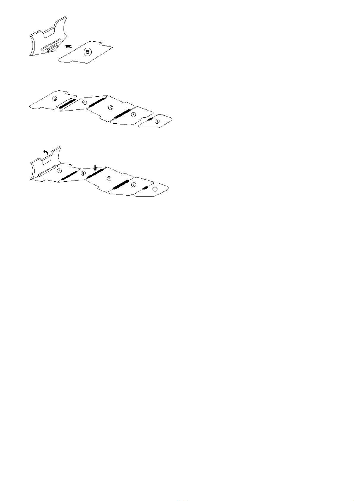
6.9.Set the lateral beams in the cut-outs provided on segments
No.5, No.4, No.3 (Fig.10). To do it, place the beam in the boat
from one side in opposition to the cut-outs, hook the boarding
edge with the beam from below and make a pushing motion from
top to bottom and forward. Thereat, your may hold up the floor
edge from below through the bottom.
Check to ensure that the beams do not "catch" the balloon. The
segment edges should enter the beam cut-outs tightly.
6.10.Make sure again that the edges of the segments and beams fall
within the folding line of the balloon and bottom connecting tape.
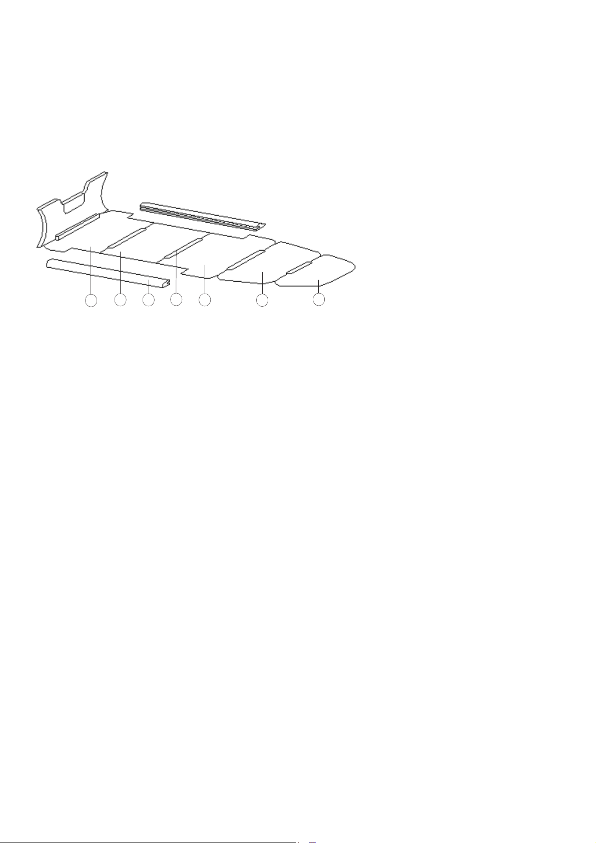
6.11.Check to ensure that the rigid boarding was assembled
correctly: the segments should be arranged closely to each other
without misalignment in the increasing order of the numbers from
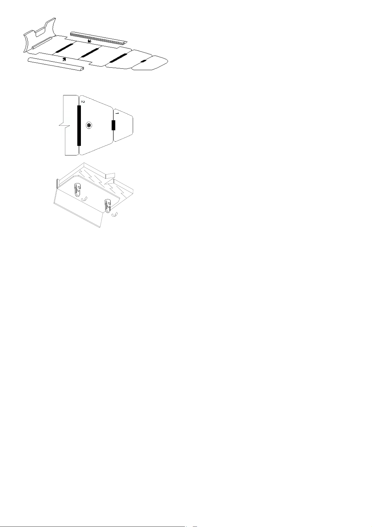
the bow to the aft of the boat. The keel valve should fall within
the centre of the hole of segment No.2 (Fig.11). If the keel
valve is outside the centre of the hole of segment No.2 adjust the
keel position by taking hold of the valve flange and raising the
boat bow by the lifeline. Reset the valve.
6.12.Set the rigid seat as shown in the figure 12.
To do it, insert the fixing devices arranged on the lower surface of
the wooden seats into the holes of the brackets pasted onto the
balloon. Turn and fix lugs of the fixing devices till they clicked as
shown in the figure.
6.13.Fill the balloon compartments with air using the pump from the
complete set. First fill the aft compartments, then medium compart-
ments and, finally, bow compartment. Thereat, do not bring the
pressure up to its operating value.
6.14.After all the compartments are filled check to ensure that the
boarding is arranged correctly inside the Boat.
If necessary, set the boarding as required by applying a force to the
edges of the boarding segments.
Fig.10
Fig.11
Fig.12a

–11–
2359.01 HD Series
Fig.12b
6.15.Bring the pressure in the compartments up to the operating
value (0.15 kgf/cm2). Afterwards, close reliably the inlet holes of
the valves.
6.16.Fill the inflatable keel with air up to the rated pressure value.
6.17.Assemble the oars by entering the removable parts with
blades into the locks until the click. Make use of the holes provided
in the oar handles to set the oars into the rowlocks with the blades
being faced to the aft. Secure the oars in the holders.
6.18.Close the water discharge valve holes with plugs.
6.19.Mount the outboard engine on the transom.
6.20.Arrange the fuel tank in a special place on the boarding. The tank
shall tightly seat between the restraining planks. Secure the tank with
belts.
7. SAFETY PRECAUTIONS AT OPERATION.
7.1.Before to start handling of the Boat read thoroughly this User's manual.
7.2.Before each usage check the Boat for completeness. The Boat may be used only provided its complete set complies with Section 3 of the
User's manual.
7.3.The Boat with an outboard engine may only be handled by the persons officially authorized to handle small-size vessels and having
appropriate job skills.
7.4.All operations associated with handling of the Boat and the outboard engine shall be performed in compliance with the User's manuals for
the Boat and outboard engine.
7.5.Before usage inspect the Boat, its components and make sure that they are ready for usage.Until sailing satisfy oneself that drain opening
on a transom is closed by plug.
7.6.Before lowering the Boat check the attachments of the paddles to the sides, thwarts to the brackets and fuel tank to the boarding.
7.7.The Boat lowering and lifting operations shall be performed with the help of a boat davit from the deck which should be free from
sharp protruding ship’s structures and parts which could damaged the fabric of the Boat.
Fig.12c

–12–
It’s forbidden to lift/to lower the Boat with the people inside.
7.8.In case of alongside landing of the Boat and its lying alongside a vessel, an excessive friction of the Boat against the board shall be avoided.
7.9.Any cargo having sharp edges, as well as active chemical agents which may cause damage to the coating and textile base of the material
of the Boat sides and bottom shall not be allowed to be loaded in the Boat.
7.10.All crew members and passengers shall wear standard life-saving jackets.
7.11.Navigation of the Boat shall be allowed by at least two men.
7.12.As pressure drops in the process of the usage of the Boat it shall be pumped up by means of bellows via the fill valves.
7.13.If the Boat is used for carriage of cargo heavier objects shall be arranged as low as possible and secured reliably.
7.14.In the process of the use and storage the Boat shall be protected against open fire and the material of the bottom and sides shall be
protected against mechanical injuries.
7.15.Before lowering and lifting of the Boat in each particular case serviceability of the attachment points, slings, as well as air-tightness of
the Boat shall be thoroughly checked.
7.16.The Boat shall be covered if stored in the filled up condition on the deck of the vessel.
7.17.Water shall be removed from the Boat via the water discharge valves before arranging the Boat on the keel-blocks on completion of its use.
7.18.It is forbidden to handle the Boat with the power of an outboard engine exceeding the maximum allowable value (see Table.1)
7.19.Before starting to handle the Boat all operations complying with Section 6 of the User's manual shall be performed.
7.20.The Boat shall be towed at a speed not exceeding 5 knots (9.25 km/hour) with the use of a line at least 15 m in length.
8. MAINTENANCE SERVICING
8.1.The condition of the surfaces of the boarding, transom and rigid seat shall be checked. If a damage to the paintwork is detected
the faulty components shall be thoroughly dried and the protective coating restored.
8.2.Minor repairs (removal of balloon or bottom punctures and cuts) may be performed independently by making use of fabric and
adhesive from the repair kit. Independent performance of complex repair associated with a considerable damage to the side, partitions
and seals is not recommended. In such cases, one shall apply to the Manufacturer.
8.3.Before handling the Boat the balloon air pressure shall be tested. The testing is made by pressing the side of the Boat with the
base of the palm and inspecting visually the depth of deflection which shall not exceed 20 mm. If necessary, the pressure shall be brought
up to the operating value. In this case, the depth of side deflection shall not exceed 10 mm.

–13–
2359.01 HD Series
8.4.No water shall penetrate inside the balloons of the Boat and any contacts of fuel and oil with its external surfaces shall be avoided. In
case of fouling of surfaces of the Boat with combustible materials, a fouled place shall be thoroughly washed with soapy water and dried out.
Avoid an excessive increase of pressure in the balloons of the Boat, especially, by its exposure to direct sunlight.
9. STORAGE AND TRANSPORTATION
9.1.To prepare the Boat for storage, pump it up, thoroughly clean the boarding, thwart to remove dirt, blow them over with compressed
air or dry them up outdoors in a shadowed place.
9.2.Proceed to folding from the afterbody of the Boat. Open the valves and switch the valves over into condition "OPEN" (look before).
9.3.The Boat shall be stored in the standard package in a dry closed room at temperature from 0 to +20°C. Storage of the Boat with
temperature variations from minus 30°C to plus 45°C may be allowed for not longer than 1 month. The Boats to be stored under the subzero
temperature conditions shall be maintained packed within at least 1 hour at temperature above 0°C.
9.4.While been stored the Boat shall be protected against direct sunlight. The Boat shall be at least 0.5 m distant from the walls and
the floor of the storeroom and at least 1 m distant from heating elements.
9.5.The Boats may not be stored in the common room with active chemical agents which might cause damage to the coating and textile
materials, as well as to adhesive joints.
9.6.The Boats packed in covers and cartons may be transported by all means of transport.
In case of transportation of the Boat together with its wooden accessories, the latters shall be isolated from the fabric of the Boat by
means of paper or a layer of cloth.
In case of transportation of the Boat in the assembled/disassembled condition, one shall avoid sharp pounding, kicks, jerks, and shocks
which may cause damage to the components of the Boat.

–14–
10. POTENTIAL TROUBLES AND TROUBLE-SHOOTING METHODS.
Type of trouble Probable cause Trouble-shooting method
1. Boat's body is not air-tight Puncture, cut, stripping of fabric Apply strengthening means.
Unsticking of tapes, lamination of seals Stick tapes, bond seals.
Leakages through fill valves Check tightness of connection
between valves and flanges.
Change packing rings.
Change valve.
2. Penetration of water inside Boat Damage to bottom fabric Apply strengthening means
3. Flaking off of paintwork from Coat damaged parts with three
wooden parts layers of polyurethan or similar
toit, sea water resistant,paint.
4. Separation of veneer from transom, Apply epoxy resin to secure places
keel, boarding and thwarts of separation.
Perform repair of fabric parts of the Boat according to the following procedure: clean the damaged place of the Boat to remove dirt,
use the cloth from the repair kit to cut out a patch of a required size to overlap the damaged place by at least 20 mm, round off the corners
of the patch. Treat the surfaces to be bonded using clean cloth soaced in acetone or ethylacetate. Apply two layers of adhesive to the
damaged section and strengthening means (patch) with the 5-minute interval being made. On spreading adhesive for the second time
wait for 3 minutes and then touch the stiffened adhesive with your finger to make sure that it does not stick. Apply the patch to the
damaged place without folds and wrinkles and roll it over using an object of cylindrical form.
After repair hold the Boat for at least 24 hours, then fill it up with air and test for leakproofness.
Perform repair at temperature not below - 18 C. If necessary, warm up the zones to be bonded with dry hot compressed air (50 C).
In case of veneer separation, use epoxy resin for repair. First clean the surfaces to be bonded, bond the veneer to the surface and
press it against the surface with the help of a cramp to ensure as tight connection as possible for the period of time specified in the
instructions on the use of this type of resin.

–15–
2359.01 HD Series
CONTENTS
INTRODUCTION 2
1. PURPOSE 2
2. SPECIFICATIONS 2
3. COMPLETE DELIVERY SET 3
4. BOAT DESIGN 4
5. DESIGN AND OPERATION OF BOAT COMPONENTS AND ASSEMBLIES 6
5.1. ENGINE UNIT 6
5.2. RIGID BOARDING 6
5.3. VALVES 7
5.4. SUSPENSION OF BOAT ON HOOKS 8
6. ASSEMBLY PROCEDURE 8
7. SAFETY PRECAUTIONS AT OPERATION 11
8. MAINTENANCE SERVICING 12
9. STORAGE AND TRANSPORTATION 13
10. POTENTIAL TROUBLES AND TROUBLE-SHOOTING METHODS 14
ACCEPTANCE CERTIFICATE 16

MODEL
SERIAL No.
Date of manufacture
Quality inspection stamp
inflatable boats
This manual suits for next models
1
Table of contents
Other BRIG Boat manuals

BRIG
BRIG N520 User manual

BRIG
BRIG FALCON F570 User manual

BRIG
BRIG NAVIGATOR Series User manual

BRIG
BRIG FALCON Series User manual

BRIG
BRIG NAVIGATOR N485 User manual

BRIG
BRIG NAVIGATOR 26 User manual

BRIG
BRIG FALCON 2013 User manual

BRIG
BRIG EAGLE E780 User manual

BRIG
BRIG FALCON F330L User manual

BRIG
BRIG NAVIGATOR Series User manual
Popular Boat manuals by other brands

Jeanneau
Jeanneau MERRY FISHER 755 owner's manual

Brunswick
Brunswick bravo one Operation & maintenance manual

Adventure Kings
Adventure Kings AKTA-2.85KAYAK_01 user manual

Pro-Line Boats
Pro-Line Boats 35 Express 2006 owner's manual

Hobie
Hobie SPORT CRUISER 21 Assembly manual

Hobie
Hobie 3.5 Instructions for rigging