manuals.online logo
Brands
  1. Home
  2. •
  3. Brands
  4. •
  5. Bristan
  6. •
  7. Plumbing Product
  8. •
  9. Bristan SOLO SST1000-L User manual

Bristan SOLO SST1000-L User manual

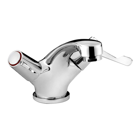
SOLO
Mixing Tap
SST1000-L
Fitting Instructions
Please keep these instructions for future reference and request of
replacement part
(FI SST1000-L) (Rev.D3)
AFTERCARE INSTRUCTIONS
Your fitting has a high quality finish and should be treated with care to preserve the
visible surfaces.
All surface finishes will wear if not cleaned correctly, the only safe way to clean your
mixer is to wipe with a soft damp cloth. Stains can be removed using washing up
liquid. All bath cleaning powders and liquids will damage the surface of your fitting,
even the non-scratch cleaners.
Installer please fill in code here
Bristan Group Limited
Birch Coppice Business Park
Dordon
Tamworth
Staffordshire
B78 1SG
UK
A Masco Company
Website: www.bristan.com
Telephone:+44 (0) 844 701 6274
Facsimile: +44 (0) 844 701 6275
Email:
NOTE: Never use abrasive detergents or disinfectants or those containing
alcohol, hydrochloric acid or phosphoric acid.
PRODUCT IDENTIFICATION CODE LASER ETCHED ON PRODUCT
. (Where applicable)
PRODUCT CODE: SST1000-L
In the interests of continuous product development we reserve the right to alter
specification as necessary
[email protected]
Bristan recommend E-Cloth for cleaning all of our
bathroom & kitchen products. Using just water, E-cloth
gives a smear free, deep clean by breaking up and holding
dirt, which normal cloths leave behind. Order through
your Bristan stockist. (ORDER CODE: ECLOTH)
800114C
SOLO MIXING TAP
Fig 1.
15mm compression
45mm
max 140.0mm
GUARANTEE - SERVICE POLICY (Available in UK and ROI only)
This product is guaranteed against faulty materials and workmanship for 12 months
from date of purchase. For the guarantee to be valid, the unit must be installed by a
competent person, in accordance with the instruction booklet.
Any part found to be defective during the guarantee period, will (at our option) be
repaired or replaced, free of charge, provided the unit has been installed, and properly
used in accordance with the instruction booklet. This guarantee does not affect your
statutory rights.
Please have the following handy: Model type, Date of purchase, Product number (if
available).
The Customer Service Department will attempt to diagnose the cause of the fault and
advise the necessary action to resolve the problem over the phone. If the fault can not
be resolved and a service call is required, a Site Visit Request form will be sent to you to
complete and return.
Where applicable a fixed fee payment for parts and/or labour will be levied. The cost
incurred and payment methods will be advised over the phone and on the Site Visit
Request form. A completed form, along with payment (if applicable) must be received
before the Service callout can be arranged.
If the fault is not product related or is a component not of our manufacture, a fixed fee
will be made to cover Site visit costs. Additional costs for parts used to rectify related
problem may be imposed.
During the visit, yourself or a responsible person should be present at all times.
Charges will be made if the Service Engineer or Agent can not gain site access at the
prearranged time.
Ensure water and/or electricity supplies have adequate isolation to the unit. If the unit is
concealed, serviceable access should be available. If servicing difficulties arise from not
making the provisions detailed, additional time related costs or a recall charge will be
imposed.
SPECIFICATION
INSTALLATION REQUIREMENT NOTES:
IRN R001
IRN R006
IRN R010 Schedule 2-15 (1)
OPERATION
The SoloTAP is a single sequential control spray mixing tap giving COLD and HOT
within ½ turn of the knob or lever.
It has been designed to conform to BS 5779.
The SoloTAP is fitted with stainless steel flexible hoses which suit various inlet
positions.
Isolating adapters are provided as standard to connect the SoloTAP to15mm copper
pipe
Operating on unequal pressures:
Minimum head pressure: 0.2 bars (2 metre head)
Maximum head pressure: 5 bars (50 metre head)
Outlet flow: 1.8 to 3.6 litres/min approx.
Fitted in a system where pressure drops are unlikely should give a stable temperature.
See text of entry for Installation Requirement Notes.
If this tap or combination tap is installed so that its base is no lower than the spillover
level of the receiving vessel, (for example, a sink or washbasin), a type AUK3 air gap is
achieved which permits installation of tap in any premises where backflow protection up
to Fluid Category 5 is required at the tap.
Water supplies shall be at reasonably balanced pressures from a common source (hot
and cold supplies both from the same storage or both from a supply pipe). Where the
fitting is supplied from unbalanced supplies (hot and cold supplies from separate
sources) a 'Listed single Check Valve or some other no less effective backflow
prevention device shall be fitted immediately upstream of both hot and cold water inlets.
Turn the handle in an anti-clockwise direction. This gives cold water flow.
Further rotation of the handle gives a warmer flow and fully on gives hot.
Please note this tap turns half way.
The maximum temperature can be set by this stop. See maximum temperature stop.
PARTS LIST
1
2
3
4
5
6
7
8
9
10
11
12
13
14
15
16
17
18
19
20
21
22
23
24
25
26
27
28
29
30
No. DESCRIPTION
INDICE
LEVER
SPINDLE STOP PLATE
TAP STOP
SPINDLE
TAP HEAD
O RING
HOT VALVE
SPINDLE SCREW
CIRCLIP
PLAIN WASHER
CRINKLE WASHER
O RING
PTFE WASHER
VALVE OPERATOR
COLD VALVE
VALVE GUIDE
O RING (x2)
SHUT OFF BALL (x2)
SHUT OFF SPRING (x2)
SCREW (x2)
CHROME BODY
BASE FLANGE
PLASTIC WASHER
BACKNUT
FLEXIBLE HOSE (x2)
O RING
SPRAY NOZZLE
HOT LABEL
COLD LABEL
88mm
2L
21
22
23
24
25
26
27
32mm
60mm
28
Ø45mm
3/4” BSP
INSTALLATION
MAXIMUM TEMPERATURE SETTING
The SoloTAP comes complete with stainless steel flexible hoses with 15mm
compression fit with isolation.
1) Before connecting the hot and cold supply pipes flush through thoroughly to remove
any debris.
2) When fitting the tap both the hoses need to be removed. Unscrew the hot side
before the cold side. They are marked with red and blue labels for identification.
When re-fitting replace the cold side first.
3) When the tap is viewed from the front the hot supply is on the left and the cold
supply on the right.
4) Fit the tap to the basin as shown (Fig 1) Take care not to overtighten the plastic
backnut.
5) The flexible hoses can easily be moved to connect onto 15mm copper pipe.
6) After installing the tap both the isolation adapters should be turned to the closed
position
7) The tap lever should be turned anti-clockwise to the full open position.
8) Adjust the hot flow by the isolation adapter to give a spray pattern (Fig 4). This is
easily achieved by turning the isolating adapter to full flow (Fig 3) and then reducing
to the curved spray pattern as shown in Fig 4.
9) Turn the handle clockwise to reduce hot flow to a trickle.
10) Then open the cold flow isolation adapters to give a curved spray pattern again as
shown in Fig 4.
Your SoloTAP is now ready for use.
We recommend that after installation the SoloTAP should be tested at the fully open
position for the maximum outlet temperature. To adjust the outlet water temperature
follow the steps below:
Prise out indice then remove screw.
Turn lever anti-clockwise to give required maximum outlet temperature.
At this point pull off lever.
Remove spindle stop plate from the spindle and replace on the spindle ensuring that the
stop plate butts against the black plastic tap stop (Fig 2)
Now check the outlet temperature to ensure no movement of the spindle has occurred
during this setting.
Re-fit lever.
Basic plastic
tap stop
Spindle stop
plate
Spindle stop plate
to butt against plastic tap stop
Fig 2.
Fig 4.Fig 3.
CLEANING / MAINTENANCE
The spray nozzle should be cleaned periodically to remove scale or other particles
which can reduce the performance of the tap.
This can be removed by using a 0.820” (21mm) A/F spanner
The chrome surfaces maybe cleaned using a soft damp cloth and mild detergent only.
Abrasive or solvent cleaning fluids are not recommended.
Isolate both hot and cold supplies at mains.
Prise out indice then remove screw and pull off lever.
From inside the tap body remove the head with 0.920” A/F - ½” B.S.W. Spanner
From inside the tap body remove the hot valve and the cold valve from the valve guide.
Note: please ensure they are re-assembled in the same ports as they control the
sequential mixing of the tap.
Unscrew the stainless steel screws to remove the valve guide and prise out both orings,
shut off balls and springs.
See maximum temperature setting to set the maximum outlet temperature after re-
assembly.

Other Bristan Plumbing Product manuals

Bristan PS2 BAS C D2 Wiring diagram

Bristan

Bristan PS2 BAS C D2 Wiring diagram

Bristan CR SHXDIVFF C Mounting instructions

Bristan

Bristan CR SHXDIVFF C Mounting instructions

Bristan EXD BAS C User manual

Bristan

Bristan EXD BAS C User manual

Bristan FHC CTRD01 C User manual

Bristan

Bristan FHC CTRD01 C User manual

Bristan PIV BSM C User manual

Bristan

Bristan PIV BSM C User manual

Bristan Nero NRBSME6C Wiring diagram

Bristan

Bristan Nero NRBSME6C Wiring diagram

Bristan Palermo PA BSM C User manual

Bristan

Bristan Palermo PA BSM C User manual

Bristan FHC CTRD02 C User manual

Bristan

Bristan FHC CTRD02 C User manual

Bristan Pisa PS2 BAS C Wiring diagram

Bristan

Bristan Pisa PS2 BAS C Wiring diagram

Bristan AR3 SHCDIV C Wiring diagram

Bristan

Bristan AR3 SHCDIV C Wiring diagram

Bristan JU BAS C User manual

Bristan

Bristan JU BAS C User manual

Bristan Prism User manual

Bristan

Bristan Prism User manual

Bristan SK1850- SK1850-2 Original operating manual

Bristan

Bristan SK1850- SK1850-2 Original operating manual

Bristan COB SHC3STP C (D9) Wiring diagram

Bristan

Bristan COB SHC3STP C (D9) Wiring diagram

Bristan RO2 SHXAR C Mounting instructions

Bristan

Bristan RO2 SHXAR C Mounting instructions

Bristan CRZ SHXDIVCTFF C Wiring diagram

Bristan

Bristan CRZ SHXDIVCTFF C Wiring diagram

Bristan VR1000 User manual

Bristan

Bristan VR1000 User manual

Bristan RV SNK C User manual

Bristan

Bristan RV SNK C User manual

Bristan Jute JU BSM C User manual

Bristan

Bristan Jute JU BSM C User manual

Bristan W BATH05 C Wiring diagram

Bristan

Bristan W BATH05 C Wiring diagram

Bristan W BATH07 C Wiring diagram

Bristan

Bristan W BATH07 C Wiring diagram
Bristan W BTH12 C User manual

Bristan

Bristan W BTH12 C User manual

Bristan Joy care Mounting instructions

Bristan

Bristan Joy care Mounting instructions

Bristan Descent Series User manual

Bristan

Bristan Descent Series User manual

Popular Plumbing Product manuals by other brands

Axel ARAX.8105CR quick start guide

Axel

Axel ARAX.8105CR quick start guide

Brizo HK32 Series quick start guide

Brizo

Brizo HK32 Series quick start guide

KWC Vesuno K.12.VB.92.700A26 Specification sheet

KWC

KWC Vesuno K.12.VB.92.700A26 Specification sheet

Spectrum Brands Pfister Woodbury RT6-5WD Quick installation guide

Spectrum Brands

Spectrum Brands Pfister Woodbury RT6-5WD Quick installation guide

DXV Keefe D35104.430 installation instructions

DXV

DXV Keefe D35104.430 installation instructions

Insignia RW102 installation manual

Insignia

Insignia RW102 installation manual

Bossini Asta Saliscendi DE6000B Installation and maintenance instructions

Bossini

Bossini Asta Saliscendi DE6000B Installation and maintenance instructions

Westfalia 81 29 64 instruction manual

Westfalia

Westfalia 81 29 64 instruction manual

BELLOSTA f-vogue bijoux 3303/2 Installation instruction

BELLOSTA

BELLOSTA f-vogue bijoux 3303/2 Installation instruction

Laufen LIS CW2 Assembly and installation

Laufen

Laufen LIS CW2 Assembly and installation

IKEA BROGRUND quick start guide

IKEA

IKEA BROGRUND quick start guide

Hans Grohe Metropol Series Instructions for use/assembly instructions

Hans Grohe

Hans Grohe Metropol Series Instructions for use/assembly instructions

SFA SANICUBIC 1 Installation and maintenance instructions

SFA

SFA SANICUBIC 1 Installation and maintenance instructions

Kallista P72044 installation guide

Kallista

Kallista P72044 installation guide

Hans Grohe Allegro E 06461 1 Series Installation instructions / warranty

Hans Grohe

Hans Grohe Allegro E 06461 1 Series Installation instructions / warranty

Axor Starck 10651007 Instructions for use/assembly instructions

Axor

Axor Starck 10651007 Instructions for use/assembly instructions

RAVAK NAUTILUS Installation and startup

RAVAK

RAVAK NAUTILUS Installation and startup

Primagran Riga 60 quick start guide

Primagran

Primagran Riga 60 quick start guide

manuals.online logo
manuals.online logoBrands
  • About & Mission
  • Contact us
  • Privacy Policy
  • Terms and Conditions

Copyright 2025 Manuals.Online. All Rights Reserved.