manuals.online logo
Brands
  1. Home
  2. •
  3. Brands
  4. •
  5. Broyce Control
  6. •
  7. Relay
  8. •
  9. Broyce Control P50EFR User manual

Broyce Control P50EFR User manual

Broyce Control Ltd., Pool Street, Wolverhampton, West Midlands WV2 4HN. ngland
Tel: +44 (0) 1902 773746 Fax: +44 (0) 1902 420639 mail: sales@broycecontrol.com Web: www.broycecontrol.com
The Information provided in this literature is believed to be accurate (subject to change without prior notice); however, use of such information shall be entirely at the user’s own risk
P50 FR-4-A.DOCX
Page 1 of 2
1806
•
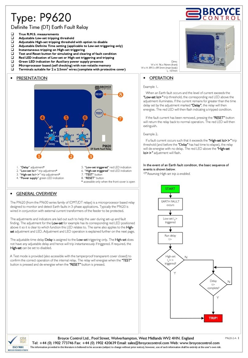
FUNCTION DIAGRAM
Terminal Protection
to IP20

Panel (Flush) Mount enclosure

Adjustable side clips provide quick method of mounting (no fi ing screws required)

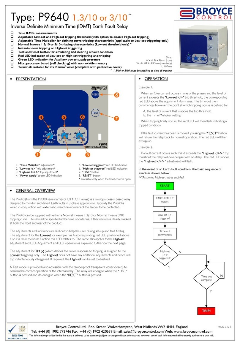
2 models available (SPDT or 2 N.O. relay outputs)

Adjustable Trip current setting (0.1 – 2A)

Adjustable Definite Time setting (0.05 – 1s)

True RMS

Separate “Test” and “Reset” push buttons

Relay energises when fault e ceeds set trip threshold

LED indication for Power Supply and Trip status

SPDT relay output - 8A (Part No. P50EFR)

2 N.O. relay outputs - 3A (Part No. P50EFR/2)

Single supply voltage option – 115V or 230V AC
Type: P50E
F
R
& P50EFR/2
Earth Fault Relay (Definite Time – DT)
•
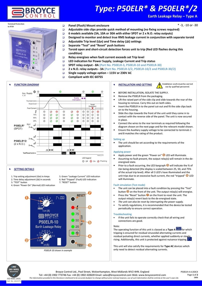
INSTALLATION AND SETTING
•B FOR INSTALLATION, ISOLAT TH SUPPLY.
•Remove the P50 FR from the packaging.
•Lift the raised part of the side clip and slide towards the rear of the
housing to remove. Carry this out on both sides.
•Insert the P50 FR in to the panel cut-out and fit the side clips back
on to the housing.
•Slide the clips towards the front of the unit until they come in to
contact with the reverse side of the panel. The unit is now secured
in place.
•Connect the wires to the rear terminals as required following the
diagram shown on the next page and for the relevant model shown.
•nsure the Auxiliary supply voltage to be connected to terminals 1
and 8 matches the rating of the product.
Setting up
•The unit should be set according to the requirements of the
application.
Applying power
•Apply power and the green “Power on”
➍
L D will illuminate.
•Assuming no fault present, the output relay(s) will remain in the de-
energised state.
•If a fault is detected, the red L D
➎
will remain constantly lit for the
set delay “t”. If the unit trips, the red L D will then flash.
Fault simulation (Test mode)
•
The unit can be placed into a fault condition by pressing the “Test”
button
➌
on the front of the unit. The output relay(s) will energise.
•
Press the “Reset” button
➏
on the front to reset the unit. The
output relay(s) revert back to the de-energised state.
•
The unit can also be reset by interrupting the power supply
•
To satisfy regulations, it is recommended that the device be tested
periodically to ensure correct operation.
Troubleshooting
•
If the unit fails to operate correctly check that all wiring and
connections are good.
•
SETTING DETAILS
➌
➋
➊
➏
➍
➎
1. “Trip current Io>” (Current setting) adjustment 4. Green “Power On” (Normal) L D indication
2. “Time delay” (Operating time) adjustment 5. Red “Tripped” L D indication
3. “T ST” button 6. “R S T” button
Broyce Control Ltd., Pool Street, Wolverhampton, West Midlands WV2 4HN. ngland
Tel: +44 (0) 1902 773746 Fax: +44 (0) 1902 420639 mail: sales@broycecontrol.com Web: www.broycecontrol.com
The Information provided in this literature is believed to be accurate (subject to change without prior notice); however, use of such information shall be entirely at the user’s own risk
P50 FR-4-A.DOCX
Page 2 of 2
1806
•
DIMENSIONS
•
CONNECTION DIAGRAM
•
TECHNICAL SPECIFICATION (continued)
Output (continued)
lectrical life: DC load capacity:
Switching current (A)
DC current (A)
Dielectric voltage: 1kV AC (rms) I C 60947-1
Rated impulse withstand voltage: 4kV (1.2/50µS) I C 60664-1
Housing
Material: Grey flame retardant Lexan UL94 V0
Weight: ≈ 225g
Protection: IP40 (front face) / IP20 (rear)
Mounting: Panel mount. Cut-out (see information below)
Max. panel thickness: 10mm
Rear Terminals
Conductor size:
0.3 – 2mm
2
(22 – 14AWG)
Wire stripping length: ≈ 6mm
Recommended tightening torque: 1.3Nm (12lb-in)
Standards
Product:
I C 255-3, I C 60255-151
MC: I C 60255-26, I C 61000-4 Series
C and RoHS Compliant. C-tick
Ordering:
Please specify product part number and voltage when ordering.
For example:
P50EFR/2 230V AC
Type:
P50EFR & P50EFR/2
Earth Fault Relay (Definite Time – DT)
•
TECHNICAL SPECIFICATION
Au iliary Power Supply (1, 8)
Supply voltage (Un): 115V or 230V AC (To be specified when ordering)
Frequency range: 50/60Hz
Supply variation: 85 – 115% of Un
Auxiliary supply is galvanically isolated from the CT input
Overvoltage category: III
Rated impulse withstand voltage: 4kV (1.2/50µS) I C 60664-1
Power consumption (max.): 3VA
Monitored input (via e ternal Current Transformer connected to terminals 2 and 7)
Rated current input (In): 5A (directly connected)
Rated frequency: 50Hz
Burden: <0.4VA @ In
Overload: 4 x In (continuous)
CT recommendation: Class P (with 5A secondary)
Device Characteristics
Measurement principle: True R.M.S.
Trip current [Current setting]
(Io>): 0.10 – 2.0A (2 – 40%)
Time delay [Operating time] (t): 0.05 – 1.0s
Pick up value: +2% of trip value
Accuracy:
Trip current: ± 5%
Time delay: ± 5% (with a minimum of 50ms)
Repeat accuracy: ± 0.5% @ constant conditions
LED indication
Power Supply: Green x1
Tripped: Red x 1
Test and Reset
“Test” method
(assuming unit is in the non-
tripped state):
Press once to trip the unit
“Reset” method
(assuming unit is in the tripped
state and fault current cleared):
Press once to reset the unit
Temperature rating
Operating: P50EFR P50EFR/2
-10 to +60°C -10 to +55°C
Storage: -30 to +70°C
Relative humidity: +95% max.
Output - Model No./Type P50EFR P50EFR/2
Rear Terminal No. (3, 4, 5) (3, 4 / 5, 6)
Contact arrangement: 1 x SPDT 2 x SPNO
AC1 (250V) 8A (2000VA) 3A (750VA)
AC15 (250V) 2.5A 1.5A
DC1 (25V) 8A (200W) 3A (75W)
Cycles
DC Voltage (V)
Resistive
load
250V AC
AC1
Resistive load
•
CUT-OUT
Key: P50 FR
P50 FR/2
This manual suits for next models

1

Other Broyce Control Relay manuals

Broyce Control ELR01PN User manual

Broyce Control

Broyce Control ELR01PN User manual

Broyce Control P9690 User manual

Broyce Control

Broyce Control P9690 User manual

Broyce Control P9600 Series User manual

Broyce Control

Broyce Control P9600 Series User manual

Broyce Control ELRV-30 User manual

Broyce Control

Broyce Control ELRV-30 User manual

Broyce Control P9680 User manual

Broyce Control

Broyce Control P9680 User manual

Broyce Control P50ELR Series User manual

Broyce Control

Broyce Control P50ELR Series User manual

Broyce Control P9620 User manual

Broyce Control

Broyce Control P9620 User manual

Broyce Control ELRV-30 User manual

Broyce Control

Broyce Control ELRV-30 User manual

Broyce Control P9680C User manual

Broyce Control

Broyce Control P9680C User manual

Broyce Control P9650 User manual

Broyce Control

Broyce Control P9650 User manual

Broyce Control P9625 User manual

Broyce Control

Broyce Control P9625 User manual

Broyce Control EcoSmart P9670 User manual

Broyce Control

Broyce Control EcoSmart P9670 User manual

Broyce Control P9640 User manual

Broyce Control

Broyce Control P9640 User manual

Broyce Control P9660 User manual

Broyce Control

Broyce Control P9660 User manual

Popular Relay manuals by other brands

Microelettrica Scientifica MC2-30T Operation manual

Microelettrica Scientifica

Microelettrica Scientifica MC2-30T Operation manual

EUCHNER ESM-CB operating instructions

EUCHNER

EUCHNER ESM-CB operating instructions

Farfisa 2281Q manual

Farfisa

Farfisa 2281Q manual

Toshiba GRD150 manual

Toshiba

Toshiba GRD150 manual

Doepke DMD 2 Installation and operating manual

Doepke

Doepke DMD 2 Installation and operating manual

Chauvet Synapse 4 Quick reference guide

Chauvet

Chauvet Synapse 4 Quick reference guide

F&F SWITCH & ENERGY Wi-R1S1-P manual

F&F

F&F SWITCH & ENERGY Wi-R1S1-P manual

steute Ex AZM 415 Mounting and wiring instructions

steute

steute Ex AZM 415 Mounting and wiring instructions

Dossena DER3/0 Series manual

Dossena

Dossena DER3/0 Series manual

GE MM200 quick start guide

GE

GE MM200 quick start guide

Leviton EZ-MAX Plus 8 quick start guide

Leviton

Leviton EZ-MAX Plus 8 quick start guide

MICROMATIC WRU-10 RAL manual

MICROMATIC

MICROMATIC WRU-10 RAL manual

ABB TF65 operating instructions

ABB

ABB TF65 operating instructions

Weil-McLain WMR Series instruction manual

Weil-McLain

Weil-McLain WMR Series instruction manual

LSIS EMPR Series manual

LSIS

LSIS EMPR Series manual

Omron K8DT-PZ Series manual

Omron

Omron K8DT-PZ Series manual

Siemens SIRIUS Series Original operating instructions

Siemens

Siemens SIRIUS Series Original operating instructions

Siemens siprotec 7SJ63 instruction manual

Siemens

Siemens siprotec 7SJ63 instruction manual

manuals.online logo
manuals.online logoBrands
  • About & Mission
  • Contact us
  • Privacy Policy
  • Terms and Conditions

Copyright 2025 Manuals.Online. All Rights Reserved.