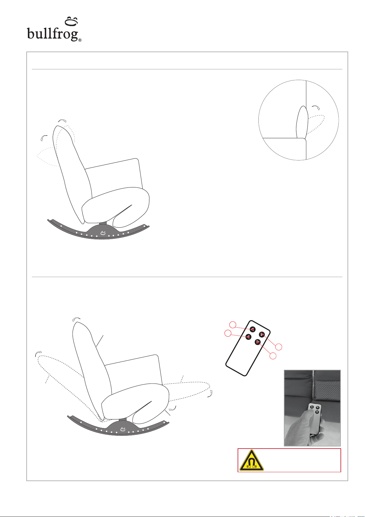
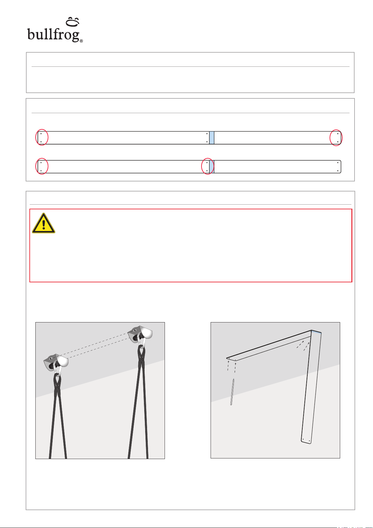
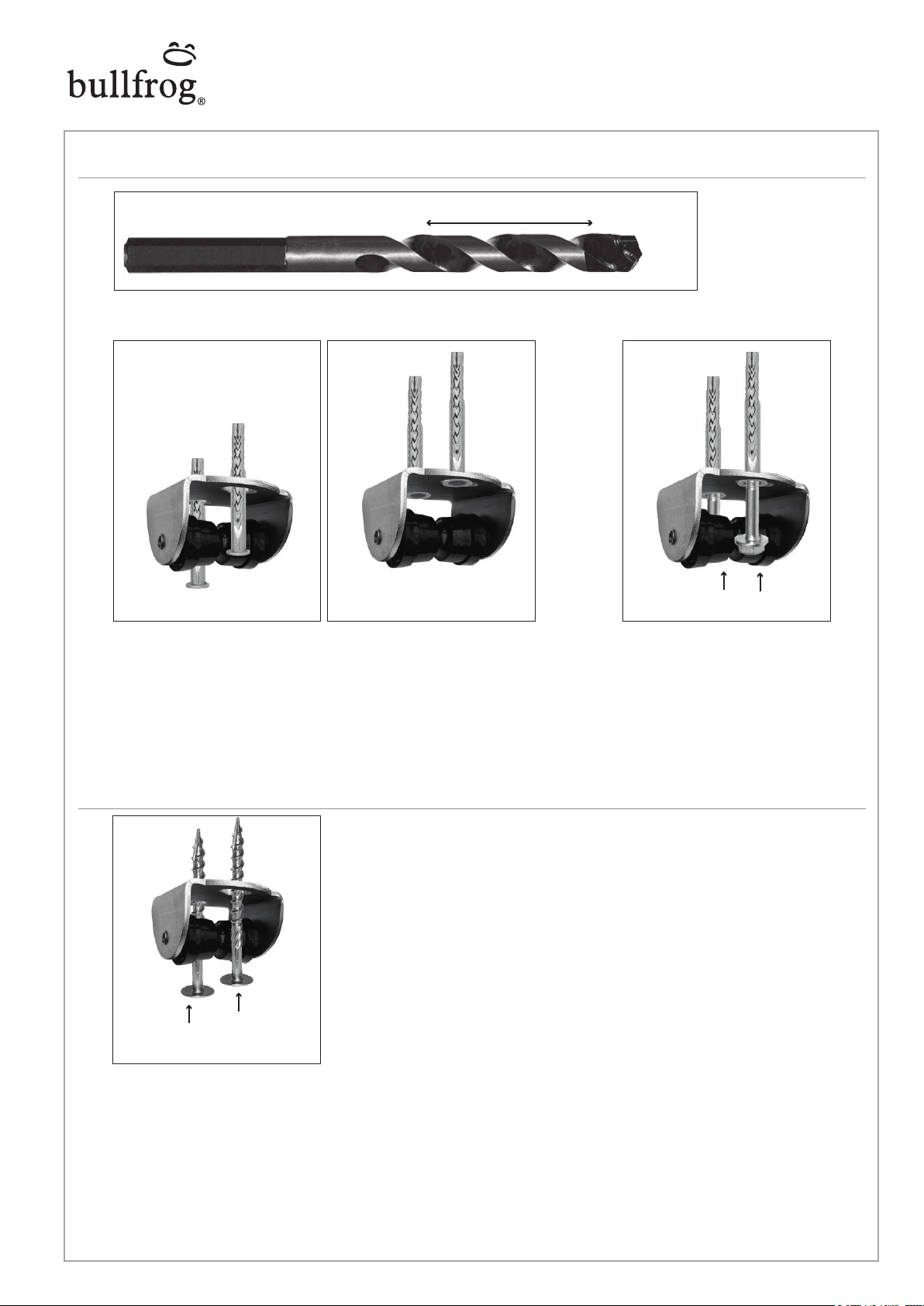
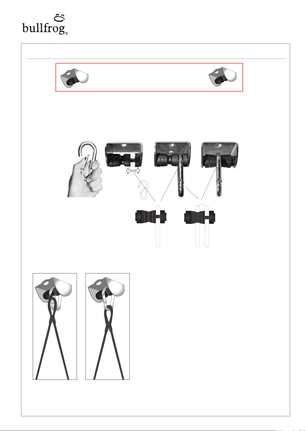
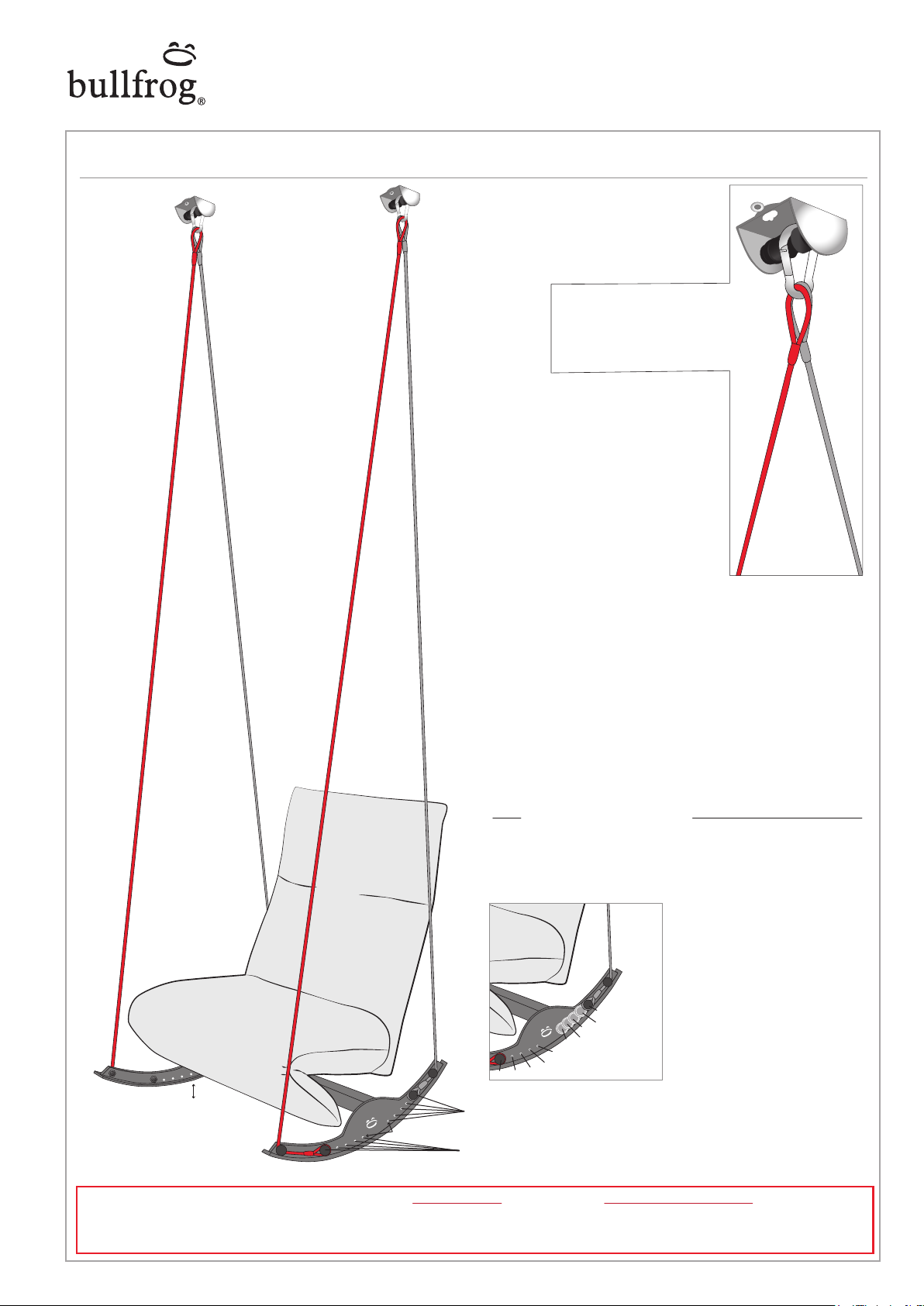
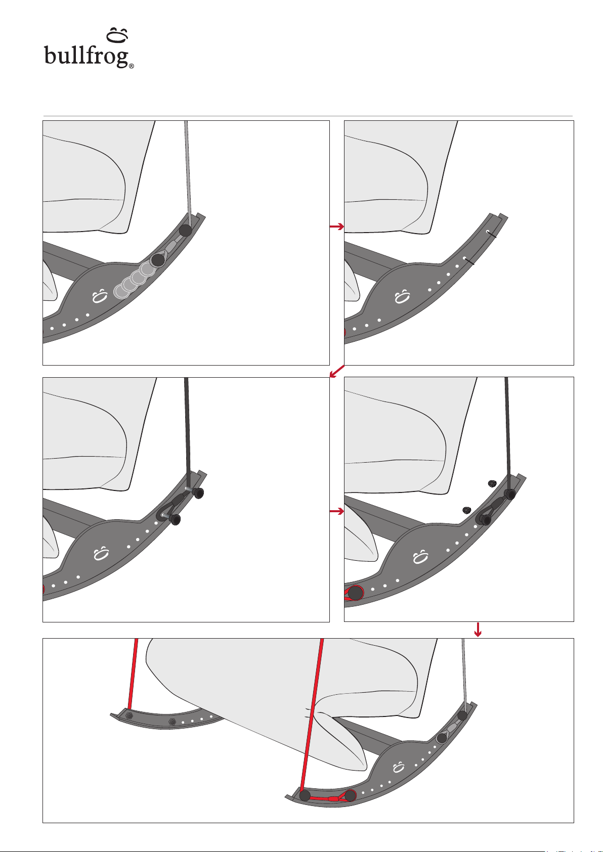
BullFrog OD0821 ROCKfrog User guide
Other BullFrog Indoor Furnishing manuals

BullFrog
BullFrog IWAN OD1070 User guide

BullFrog
BullFrog BOWL 0620 User guide

BullFrog
BullFrog 1121 OLALA User guide

BullFrog
BullFrog CASINO OD5728 User guide

BullFrog
BullFrog OLALA OD1121 User guide

BullFrog
BullFrog IWAN 1070 User guide

BullFrog
BullFrog OD2211 ECKfrog User guide

BullFrog
BullFrog 0520 PANDA User guide

BullFrog
BullFrog CAYMAN 6660 User guide

BullFrog
BullFrog BOOGIE OD0618 User guide

BullFrog
BullFrog 0920 PIROU User guide

BullFrog
BullFrog 1044 BEO User guide

BullFrog
BullFrog LAGOON 1520 User guide

BullFrog
BullFrog 0621 User guide

BullFrog
BullFrog 8200 SOLID User guide

BullFrog
BullFrog 1008 BLOBB User guide

BullFrog
BullFrog 2203 TIBOU User guide

BullFrog
BullFrog OD0319 TAO User guide

BullFrog
BullFrog 0820 NAOS User guide

BullFrog
BullFrog OD1021 NEO User guide


Popular Indoor Furnishing manuals by other brands


Coaster
Coaster 4799N Assembly instructions

Stor-It-All
Stor-It-All WS39MP Assembly/installation instructions

Lexicon
Lexicon 194840161868 Assembly instruction

Next
Next AMELIA NEW 462947 Assembly instructions

impekk
impekk Manual II Assembly And Instructions

Elements
Elements Ember Nightstand CEB700NSE Assembly instructions