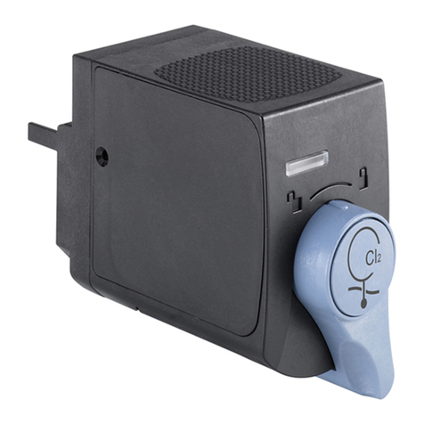
Burkert MS06 Series User manual

Operating Instructions
Type MS06
FIA sensor cube for iron content

We reserve the right to make technical changes without notice.
Technische Änderungen vorbehalten.
Sous réserve de modifications techniques.
© Bürkert SAS, 2019
Operating Instructions 1910/00_EU-ML 00568298 ORIGINAL_DE

1
Type MS06
1 ABOUT THE OPERATING INSTRUCTIONS ...........................................................................................................................5
1.1 Symbols used ..........................................................................................................................................................................5
1.2 Definition of the term product ........................................................................................................................................5
1.3 Definition of the term system ..........................................................................................................................................6
1.4 Definition of the term büS .................................................................................................................................................6
1.5 Definition of the term "reagent unit" ............................................................................................................................6
2 INTENDED USE ....................................................................................................................................................................................6
3 BASIC SAFETY INFORMATION ....................................................................................................................................................7
4 GENERAL INFORMATION ................................................................................................................................................................8
4.1 Contact ........................................................................................................................................................................................8
4.2 Warranty conditions ..............................................................................................................................................................8
4.3 Information on the Internet ...............................................................................................................................................8
5 DESCRIPTION .......................................................................................................................................................................................9
5.1 General description and function ..................................................................................................................................9
5.2 Description of the product without housing for the type 8905 .....................................................................9
5.3 Description of the product mounted in a housing for the type 8905 .....................................................10
6 TECHNICAL DATA .............................................................................................................................................................................11
6.1 Conditions of use ................................................................................................................................................................11
6.2 Conformity to standards and directives .................................................................................................................11
6.3 Materials the product is made of ...............................................................................................................................11
6.4 Fluid data .................................................................................................................................................................................11
6.5 Measurement data .............................................................................................................................................................12
6.6 Electrical data .......................................................................................................................................................................12
6.7 Data transfer ..........................................................................................................................................................................12
7 INSTALLATION ...................................................................................................................................................................................13
7.1 Safety instructions .............................................................................................................................................................13
7.2 Installation on a wall of the product with housing for the type 8905 .....................................................13
7.3 Installation of the product without housing for the type 8905 ...................................................................13
7.3.1 Arrangement and equipment of the backplanes .........................................................................14
7.3.2 Mounting of the backplanes on 2 standard rails (TS35) ...........................................................15
Table of contents
English

2
7.3.3 Mounting the product on a 4 backplane combination ...............................................................15
7.3.4 Mounting the product on a 3 backplane combination ...............................................................16
7.3.5 Installation of the reagent unit .........................................................................................................17
7.4 Fluid system installation .................................................................................................................................................17
7.4.1 Fluidic connection of the product with housing ..........................................................................17
7.4.2 Fluidic connection of the product mounted on a standard rail ................................................17
7.5 Electrical connection .........................................................................................................................................................18
7.5.1 Pin assignment for the M12 connectors .......................................................................................18
7.5.2 Connecting the product with housing to the power supply and fieldbus .............................18
7.5.3 Electrically connecting the product without housing .................................................................20
8 COMMISSIONING ...........................................................................................................................................................................21
8.1 Safety instructions .............................................................................................................................................................21
8.2 Before commissioning the product ..........................................................................................................................21
8.3 Procedure for commissioning the product ...........................................................................................................22
8.4 Procedure for commissioning after a flow interruption .................................................................................22
9 ADJUSTMENT AND OPERATION ..............................................................................................................................................23
9.1 Safety instructions .............................................................................................................................................................23
9.2 How to adjust the product .............................................................................................................................................23
9.3 General information on the display software type ME21 ..............................................................................23
9.4 "Device" view of the product .........................................................................................................................................24
9.5 "Function" view of the product .....................................................................................................................................25
9.6 Detailed views of the büS function ...........................................................................................................................26
9.7 Setting the parameters of function FIA ..................................................................................................................28
9.7.1 Functions that can be adjusted in "Parameter" view ..................................................................28
9.7.2 Setting the time interval between 2 analyses ..............................................................................28
9.7.3 Setting the automatic start of a calibration...................................................................................29
9.7.4 Setting the automatic start of a cleaning cycle ...........................................................................29
9.7.5 Manually modifying the calibration values .......................................................................................... 30
9.7.6 Connecting the product with the reagent unit to monitor the operating agents
(only MZ30 with electronics) ...........................................................................................................30
9.7.7 Monitoring the fill level of the operating agents, MZ30 without electronics .........................31
9.7.8 Monitoring the fill level of the waste container ............................................................................31
9.7.9 Switching off the monitoring of the fill level of the waste container .......................................31
English

3
9.7.10 Setting the fill level of the waste container to zero .....................................................................32
9.7.11 Monitoring the expiration date of the operating agents (only MZ30 with electronics).......32
9.7.12 Monitoring the iron content .............................................................................................................32
9.8 Reading the product diagnosis ...................................................................................................................................33
9.8.1 Reading the current product status ...............................................................................................33
9.8.2 Reading the total operating time of the product .........................................................................33
9.8.3 Reading the number of analyses since first commissioning .....................................................34
9.8.4 Reading the number of analyses before the next automatic calibration ................................34
9.8.5 Reading the number of analyses before the next automatic cleaning ....................................34
9.8.6 Reading the connection status between the product and reagent unit ................................34
9.9 Setting maintenance work .............................................................................................................................................35
9.9.1 Reading the current function and tracking its progress ............................................................35
9.9.2 Reading the total and remaining time of a function in progress ..............................................36
9.9.3 Starting automatic analyses, calibrations and cleaning cycles ................................................36
9.9.4 Switching off automatic analyses, calibrations and cleaning cycles ......................................37
9.9.5 Setting the behaviour of the product after a power interruption .............................................37
9.9.6 Manually starting an analysis ...........................................................................................................38
9.9.7 Manually starting a calibration .........................................................................................................38
9.9.8 Manually starting a cleaning cycle ..................................................................................................39
9.9.9 Manually starting degassing ............................................................................................................39
9.9.10 Manually starting filling of the sample fluid system .....................................................................40
9.9.11 Manually starting filling of the reagent tube ..................................................................................40
9.9.12 Manually starting filling of the calibration tube .............................................................................40
9.9.13 Manually starting filling of the cleaning tube ................................................................................41
9.9.14 Manually starting commissioning ....................................................................................................41
9.9.15 Manually starting draining of the reagent tube ............................................................................42
9.9.16 Manually starting draining of the calibration tube .......................................................................42
9.9.17 Manually starting draining of the tube for cleaning solution .....................................................42
9.9.18 Activate or stop simulation of an iron content .............................................................................43
9.9.19 Hold the last measured value ..........................................................................................................44
9.9.20 Switching on the saving of the iron contents measured during calibration ..........................44
9.9.21 Switching off the saving of the iron contents measured during calibration ..........................44
9.9.22 Step-by-step replacement of operating agent bottles ..............................................................45
10 MAINTENANCE AND TROUBLESHOOTING .......................................................................................................................47
10.1 Safety instructions .............................................................................................................................................................47
English
Type MS06

4
10.2 Performing maintenance work ....................................................................................................................................47
10.3 Cleaning the outside of the product .........................................................................................................................47
10.4 Removal of the product from the backplane .......................................................................................................48
10.5 Troubleshooting, when no message is displayed .............................................................................................48
10.6 Troubleshooting if a message is displayed ..........................................................................................................49
10.6.1 Message "Low limit in reagent-solution tank detected" ............................................................49
10.6.2 Message "Low limit in cleaning-solution tank detected" ...........................................................49
10.6.3 Message "Low limit in calibration-solution tank detected" .......................................................50
10.6.4 Message "Measured Fe value too large" ......................................................................................50
10.6.5 Message "Measured Fe value too low" .........................................................................................51
10.6.6 Message "Waste container fill level limit reached" .....................................................................52
10.6.7 Message "Measured Fe value exceeds valid range" ..................................................................53
10.6.8 Message "Inlet temperature low limit" ...........................................................................................53
10.6.9 Message "Inlet temperature upper limit" .......................................................................................53
10.6.10 Message "The test of valves and pumps failed" ..........................................................................53
10.6.11 Message "Power supply voltage limit has been reached" ........................................................54
10.6.12 Message "Container 1 in MZ30 is placed at the wrong position" ..........................................54
10.6.13 Message "Container 2 in MZ30 is placed at the wrong position" ..........................................54
10.6.14 Message "Container 3 in MZ30 is placed at the wrong position" ..........................................55
10.6.15 Message "Reagent solution expiration date" ...............................................................................55
10.6.16 Message "Clean solution expiration date" ....................................................................................56
10.6.17 Message "Calibration solution expiration date" ...........................................................................56
10.6.18 Message "Communication with MZ30 failed" .............................................................................57
10.6.19 Message "Initializing communication with MZ30" ......................................................................57
10.6.20 Message "Automatic calibration failed" .........................................................................................57
11 SPARE PARTS AND ACCESSORIES ......................................................................................................................................58
12 PACKAGING, TRANSPORT ..........................................................................................................................................................58
13 STORAGE ..............................................................................................................................................................................................59
13.1 Storage of the product .....................................................................................................................................................59
13.2 Commissioning the product after a period of storage ...................................................................................59
14 DISPOSAL OF THE PRODUCT ..................................................................................................................................................59
English
Type MS06

5
About the Operating Instructions
1 ABOUT THE OPERATING INSTRUCTIONS
The Operating Instructions describe the entire life cycle of the product. Please keep these Operating Instructions
in a safe place, accessible to all users and any new owners.
The Operating Instructions contain important safety information.
Failure to comply with these instructions can lead to hazardous situations.
▶The Operating Instructions must be read and understood.
1.1 Symbols used
Danger
Warns against an imminent danger.
▶Failure to observe this warning results in death or in serious injury.
Warning
Warns against a potentially dangerous situation.
▶Failure to observe this warning can result in a serious injury or even death.
CaUTiOn
Warns against a possible risk.
▶Failure to observe this warning can result in substantial or minor injuries.
nOTiCe
Warns against material damage.
▶Failure to observe this warning may result in damage to the product or system.
Indicates additional information, advice or important recommendations.
Refers to information in the Operating Instructions or in other documents.
▶Indicates an instruction to be carried out to avoid a danger, a warning or a possible risk.
→Indicates a procedure to be carried out.
Indicates the result of a specific instruction.
1.2 Definition of the term product
The term "product" used within these Operating Instructions always refers to the sensor cube of the flow injection
analysis type MS06.
English
Type MS06

6
About the Operating Instructions
1.3 Definition of the term system
The term "system" used within these Operating Instructions, always refers to the Online Analysis System type
8905.
1.4 Definition of the term büS
The term "büS" used within these Operating Instructions always refers to the fieldbus developed by Bürkert.
1.5 Definition of the term "reagent unit"
The term "reagent unit" used within these Operating Instructions always refers to the reagent unit type MZ30.
2 INTENDED USE
Use of this product that does not comply with the instructions could present risks to people, nearby
installations and the environment.
The product is used for measuring dissolved iron in water and must be operated with reagent unit type MZ30.
▶This product must be protected against electromagnetic interference, ultraviolet rays and, when installed
outdoors, the effects of climatic conditions.
▶This product must be used in compliance with the characteristics and commissioning and use conditions
specified in the contractual documents and in the Operating Instructions.
▶Requirements for the safe and proper operation of the product are proper installation as well as careful opera-
tion and maintenance.
▶Only use the product as intended.
English
Type MS06

7
Basic safety information
3 BASIC SAFETY INFORMATION
This safety information does not take into account any contingencies or occurrences that may arise during instal-
lation, use and maintenance of the product.
The operating company is responsible for the respect of the local safety regulations including for the staff safety.
Danger
Danger due to the nature of the operating agents.
▶Observe the rules in force concerning accident prevention and safety and which relate to the use of hazard-
ous products.
▶Observe the information in the safety data sheet. The safety data sheets can be found at
- Reagent: http://sds-id.com/200123-8
- Cleaning solution: http://sds-id.com/200124-7
- Calibration solution: http://sds-id.com/200122-9
▶Use a waste container of at least 2.5 litres.
▶Dispose of waste containing chemicals produced by the system in an environmentally friendly manner.
Various dangerous situations.
To avoid personal injury take care:
▶to prevent any unintentional power supply switch-on.
▶to carry out the installation and maintenance work by qualified and skilled staff with the appropriate tools.
▶to use the product only if in perfect working order and in compliance with the instructions provided in these
Operating Instructions
▶to observe the general technical rules.
▶not to use the product in explosive atmospheres.
▶not to use the product in an environment incompatible with the materials from which the product is made.
▶not to make any modifications to the product.
nOTiCe
Elements/components sensitive to electrostatic discharges.
This product contains electronic components sensitive to electrostatic discharges They may be damaged if they
are touched by an electrostatically charged person or object. In the worst-case scenario, these components are
instantly destroyed or go out of order as soon as they are activated.
• To minimize or even avoid all damage due to electrostatic discharge, take all the precautions described in the
EN 61340-5-1 norm.
• Do not touch any of the live electrical components.
English
Type MS06

8
General information
4 GENERAL INFORMATION
4.1 Contact
To contact the manufacturer of the product, use the following address:
Bürkert SAS
Rue du Giessen
BP 21
F-67220 TRIEMBACH-AU-VAL
The addresses of our international branches can be found on the Internet at: www.burkert.com
4.2 Warranty conditions
The condition governing the legal warranty is the conforming use of the product in observance of the operating
conditions specified in these Operating Instructions.
4.3 Information on the Internet
You can find the Operating Instructions and technical data sheets regarding type MS06 at: www.burkert.com
English
Type MS06

9
Description
5 DESCRIPTION
5.1 General description and function
The product together with reagent unit type MZ30 represent a variant of the system type 8905.
You may have obtained the product as one of two possible variants:
• either mounted in a housing for the type 8905,
• or without housing for the type 8905.
The product must be used with a reagent unit. The product analyses the sample water using a reagent to
determine the iron content. The reagent, together with the required calibration solution and cleaning solution, are
provided through the reagent unit. The analysis is performed according to the principle of flow injection analysis.
Further details concerning the reagent unit can be found in the relevant Operating Instructions at:
www.buerkert.de.
5.2 Description of the product without housing for the
type 8905
Lever to lock/unlock the product (locked
position)
Electrical interface
Pins to engage and activate the
bayonet lever on the backplane
Adapter pins
Product status LED
Slot for configuration
memory
Fluid bypass
Fluid interface
Product
housing
Base plate
Fluidic interface to the tube module
Figure 1: Description of the product without housing for the type 8905
English
Type MS06

10
Description
5.3 Description of the product mounted in a housing
for the type 8905
Reagent unit type MZ30: Refer to the corresponding Operating
Instructions
Product mounted in
housing for the type
8905
Tube module between reagent unit
and product,
• Tube for the reagent inlet (labelled
REAGENT)
• Tube for the cleaning solution inlet
(labelled CLEANING)
• Tube for the calibration solution
inlet (labelled CALIBRATION)
• Tube for the waste outlet, mixed
with the 3 above named solutions
(labelled WASTE). A container for
the waste is not included in scope
of delivery.
Figure 2: Description of system type 8905 with product and reagent unit
Waste tube
OUT: Fluid outlet; connection for 6
mm diameter tube
IN: Fluid inlet; connection for 6 mm
diameter tube
Tube containing the three smaller tubes
of the tube module
Figure 3: Fluidic connections of the system with product and reagent unit
The electrical connections and sample water connections are made via the backplane of system type 8905. See
the corresponding Operating Instructions.
English
Type MS06

11
Technical data
6 TECHNICAL DATA
6.1 Conditions of use
Ambient temperature +10...+40 °C
Recommended working
temperature
+20 °C
Air humidity < 90 %, without condensation
Protection rating acc. to EN
60529
• IP65, if plugged into the backplane
• IP20 as a stand-alone product
Maximum height above sea level 2000 m
6.2 Conformity to standards and directives
The standards used to demonstrate conformity with the Directives can be consulted in the EC type examination
certificate and/or the EC declaration of conformity (if applicable).
6.3 Materials the product is made of
Part Material
Housing Polycarbonate
Seals EPDM, FKM, NBR
Lever Stainless steel
Backplane Anodized aluminium
Materials coming into contact with the sample EPDM, FKM, NBR, PMMA, PEEK
6.4 Fluid data
• Type of fluid
• pH value
• Drinking water, industrial water
• pH 4...9
Minimum flow rate See the pressure versus flow diagram in Figure 4
Water sample pressure PN1 bar
Water sample temperature +10...+40 °C
English
Type MS06

12
Technical data
Outlet pressure [bar]
Inlet pressure [bar]
0,0
0,2
0,4
0,6
0,8
1,0
200 ml/min.
460 ml/min.
380 ml/min.
300 ml/min.
220 ml/min.
110 ml/min.
0,0
0,2 0,4 0,6 0,8 1,0
Figure 4: Pressure versus flow diagram
6.5 Measurement data
Dissolved iron
• Measurement range
• Resolution
• Measurement value deviation ("Measurement value
offset", as defined in standard JCGM 200:2012)
• Measurement principle
• 0...10 mg/l
• ±0.01 mg/l
• ±0.05 mg/l or 5%
• Flow injection with photometric detection
6.6 Electrical data
Operating voltage 24 V DC, via the backplane of system type 8905
Power consumption 2,2...12,7 W
6.7 Data transfer
Internal data transfer via the büS
External communication via status LED In accordance with NAMUR NE 107
English
Type MS06
13
Installation
7 INSTALLATION
7.1 Safety instructions
nOTiCe
Risk of damage to the product due to non-conforming installation
• The electrical and fluidic installations can only be carried out by qualified and skilled staff with the appropriate
tools.
• Respect the installation instructions of the system.
nOTiCe
Risk of damage to the product due to the power supply.
• Shut down and isolate the electrical power source before carrying out any work on the system.
nOTiCe
Risk of damage to the product due to the environment
• Protect the products against electromagnetic interference.
7.2 Installation on a wall of the product with housing
for the type 8905
When installing the product, refer also to the Operating Instructions of reagent unit MZ30.
A slanting position of the product can lead to errors during sampling.
▶Mount the housing as vertically as possible.
→Install the product with housing for the type 8905 on a wall as described in the Operating Instructions of the
type 8905.
7.3 Installation of the product without housing for the
type 8905
If the product is supplied without housing, it can be mounted on either a 3 or a 4 backplane combination and the
backplanes are installed on a standard rail (TS35). Respect the installation instructions: chap. 7.3.1 Arrangement
and equipment of the backplanes, chap. 7.3.2 Mounting of the backplanes on 2 standard rails (TS35),
chap. 7.3.3 Mounting the product on a 4 backplane combination and 7.3.5 Installation of the reagent unit.
When installing the product, refer also to the Operating Instructions of reagent unit MZ30.
A slanting position of the product can lead to errors during sampling.
▶Mount the backplanes as vertically as possible.
English
Type MS06
14
Installation
7.3.1 Arrangement and equipment of the backplanes
The 4 backplanes must be arranged and fitted as illustrated in Figure 5. The 3 backplanes must be arranged and
fitted as illustrated in Figure 6.
nOTiCe
The IP65 protection rating is not guaranteed if the blanking plates are not screwed onto the electrical
interfaces of the backplanes.
▶Make sure that each of the blanking plates illustrated in Figure 5 or in Figure 6 is equipped with a seal.
▶Make sure that the blanking plates illustrated in Figure 5 or in Figure 6 are screwed on the correct electrical
interfaces of the backplanes.
▶Tighten the blanking plates with a torque of 0.6 N·m (i. e. 0.44 ft·lbf).
Backplanes
Type ME29
with M12 plug
Type ME29 with
M12 socket Blanking plates
Free interface
Figure 5: Backplanes for the product; arrangement and fitting of a 4 backplane combination
Backplanes
Type ME29 with
M12 plug
Type ME29 with M12
socket
Blanking plates
Free interface
Figure 6: Backplanes for the product; arrangement and fitting of a 3 backplane combination
English
Type MS06
15
Installation
7.3.2 Mounting of the backplanes on 2 standard rails (TS35)
→Fix the standard rails horizontally on a flat wall suitable for the installation.
Figure 7: Wall mounting using two standard rails TS35
7.3.3 Mounting the product on a 4 backplane combination
The product creates air bubbles during sampling. Subsequent sensor cubes can be influenced by these.
▶If the product is mounted on a 4 backplane combination and more than 4 backplanes are available,
install the product as far to the right as possible.
Blanking plates with
seals
Free interface
Bayonet levers in closed
position
1. Make sure that the seal is present on the
product, on the electrical interface to the
backplane.
2. Make sure that the four bayonet levers are in the
closed position.
3. Make sure that the three blanking plates are
protecting the electrical interfaces of the
backplanes.
4. Dry the surface of the backplane.
5. Dry the surface of the product.
Screwed-on plug
Lever in unlocked
position
6. Make sure that a seal is present on each of the
four fluidic interfaces with the tube module and
that the tubes are empty.
7. Screw the tube module plug on to the product
(torque 0.15 N·m, i. e. 0.11 ft·lbf). Do not kink or
damage the tubes in the process.
8. Make sure that the product lever is against the
stop in the unlocked position and that the bolts
engage in the holes of the bayonet lever during
mounting.
9. Insert the two adaptation pins in their holes and
then plug the product in the backplane.
English
Type MS06
16
Installation
Lever in locked
position
10. Push the levers into the locked position.
The product is electrically and fluidically con-
nected to the backplane.
Figure 8: Mounting the product on a 4 backplane combination
7.3.4 Mounting the product on a 3 backplane combination
The product creates air bubbles during sampling. Subsequent sensor cubes can be influenced by these.
▶Mount the product downstream other sensor cubes.
If the product is mounted on a 3 backplane combination, install the product as far to the left as possible
so that the lever can be unlocked.
Blanking plates with
seals
Free interface
Bayonet levers in closed
position
1. Make sure that the seal is present on the
product, on the electrical interface to the
backplane.
2. Make sure that the four bayonet levers are in the
closed position.
3. Make sure the three blanking plates are protecting
the electrical interfaces of the backplanes.
4. Dry the surface of the backplane.
5. Dry the surface of the product.
6. Make sure a seal is present on each of the 4
fluidic interfaces with the tube module and that
the tubes are empty.
Screwed-on plug
Lever in unlocked
position
7. Screw the tube module plug on to the product
(torque 0.15 N·m, i. e. 0.11 ft·lbf). Do not kink or
damage the tubes in the process.
8. Make sure that the product lever is against the
stop in the unlocked position and that the bolts
engage in the holes of the bayonet lever during
mounting.
9. Insert the two adaptation pins in their holes and
then plug the product in the backplane.
English
Type MS06

17
Installation
Lever in locked position
10. Push the levers into the locked position.
The product is electrically and fluidically con-
nected to the backplane.
Figure 9: Mounting the product on a 3 backplane combination
7.3.5 Installation of the reagent unit
→Install the reagent unit so that the bottles are above the interface to MS06.
→Pay attention to the length (60 cm) of the tube module during installation of the reagent unit.
→Observe the instructions given in the Operating Instructions of the type MZ30, available at www.burkert.com.
7.4 Fluid system installation
7.4.1 Fluidic connection of the product with housing
→Observe the information in the Operating Instructions of the type 8905, available at www.burkert.com.
→Prepare a container with the following properties:
- made from a material (e.g. polyethylene) which is resistant to the operating agents of the reagent unit.
- has a minimum capacity of 2.5 litres. Enter the container capacity in the user interface, in order to gen-
erate warnings if the container needs to be emptied. See chap. 9.7.8 Monitoring the fill level of the waste
container.
→Label the container as chemical waste.
→Secure the end of the waste tube, that is outside the system, in the container.
7.4.2 Fluidic connection of the product mounted on a standard
rail
→If the product is mounted on the standard rail, connect the tube module of the reagent unit to the product.
→Connect the product to the sample water using 6-mm tubes, respecting the specified pressure and flow rate.
→Prepare a container with the following properties:
- made from a material (e.g. polyethylene) which is resistant to the operating agents of the reagent unit.
- has a minimum capacity of 2.5 litres. Enter the container capacity in the user interface, in order to gen-
erate warnings if the container needs to be emptied. See chap. 9.7.8 Monitoring the fill level of the waste
container.
→Label the container as chemical waste.
English
Type MS06

18
Installation
→Stick the supplied labels with the hazardous material symbols onto the container.
→Secure the waste tube in the container.
Sample water outlet
Sample water inlet
Figure 10: Fluidic connection of the product without housing
7.5 Electrical connection
7.5.1 Pin assignment for the M12 connectors
• The M12 plug is used to connect power supply and the fieldbus signals.
• The M12 socket is used for forwarding the voltage supply and fieldbus signals to an external device (e.g.
reagent unit type MZ30 with electronics).
The pin assignment is the same for both M12 connections of the ME29 modules and for the M12 plug of the
reagent unit.
Table 1: Pin assignment for the M12 connectors
Pin number Signal Wire colour (from housing with the cable coming
from the electronics module)
2
5
34
1
1
5
4 3
2
1 CAN_SHIELD -
2 24 V DC Red
3 0 V / GND Black
4 CAN_H White
5 CAN_L Blue
7.5.2 Connecting the product with housing to the power supply
and fieldbus
• In order to operate the products via the Bürkert-Communicator, use the büS stick set with order code
00772426. This is available as an accessory.
• To operate the product via a display of type ME21:
→Connect the M12 plug of the housing with the type MS06 via the cable gland plate on the terminal block of
the housing to the display of type ME21 and the HMIU electronics module.
English
Type MS06
Table of contents
Other Burkert Accessories manuals

Burkert
Burkert 1060 User manual

Burkert
Burkert 8020 User manual

Burkert
Burkert 8220 User manual

Burkert
Burkert S030 User manual

Burkert
Burkert 8685 User manual

Burkert
Burkert 8020 User manual

Burkert
Burkert 8030 User manual

Burkert
Burkert 8071 User manual

Burkert
Burkert FULLBORE S056 User manual

Burkert
Burkert 8741 User manual

Burkert
Burkert S070 User manual

Burkert
Burkert SE30 Ex Namur User manual

Burkert
Burkert 2509 User manual

Burkert
Burkert GENERIC 8400 User manual

Burkert
Burkert 8030 HT User manual

Burkert
Burkert 8798 User manual

Burkert
Burkert MS05 User manual

Burkert
Burkert 8008 User manual

Burkert
Burkert MS09 User manual

Burkert
Burkert 8020 Low Power Installation and operating instructions