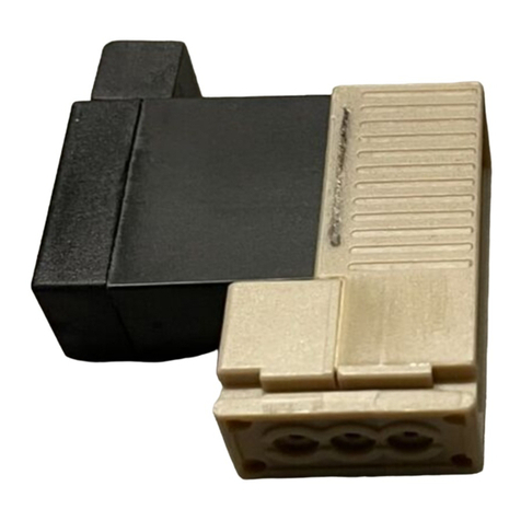
Burkert 6106 User manual

en / de / fr
Type 6106
Operating Instructions
Bedienungsanleitung
Manuel d‘utilisation
3/2-way Rocker Solenoid Valve
3/2-Wege-Wippenmagnetventil
Electrovanne à bascule 3/2 voies
Address / Adresse
Germany / Deutschland / Allemagne
Bürkert Fluid Control Systems
Sales Center
Christian-Bürkert-Str. 13–17
D-74653 Ingelfingen
Tel. + 49 (0) 7940 - 10 91 111
Fax + 49 (0) 7940 - 10 91 448
E-mail: [email protected]
International
www.burkert.com → Bürkert → Company → Locations
Manuals and data sheets on the Internet: www.burkert.com
Bedienungsanleitungen und Datenblätter im Internet: www.buerkert.de
Instructions de service et fiches techniques sur Internet : www.buerkert.fr
2/A
1/P 3/R
C 3/2 Wege-
Ventil, direkt-
wirkend,
stromlos
Ausgang 2
entlastet
3/2-way valve,
direct-acting,
disconnected
output 2
unloaded
Vanne à 3/2
voies, à action
directe, sortie
2 normalement
ouverte
D
2/A
1/P 3/R
3/2-Wege-
Ventil, direkt-
wirkend,
stromlos
Ausgang 2
druckbeauf-
schlagt
3/2-way valve,
direct-acting,
disconnected
output 2
pressurized
Vanne à
3/2 voies, à
action directe,
pression
appliquée sur
sortie 2 sans
courant
Fig./Bild 1: Circuit functions / Wirkungsweisen / fonctions
Type / Typ
Order number
Bestellnummer
N° de commande
Voltage (± 10 %) – power
Spannung (± 10 %) – Leistung
Tension (± 10 %) – puissance
Pressure range
Druckbereich
Plage de pression
Orifice / Nennweite
Diamètre nominal
Made in Germany
6106 C 0,9
P 0 - 7 bar
24 V DC 1W
W14UN
450000Y
Circuit function
Wirkungsweise
Fonction
Fig./Bild 2: Example of a type label / Beispiel eines Typschilds /
Exemple plaque signalétique
0,4 Nm
Type 2506
Seal / Dichtung /
Joint d‘étanchéité
Fig./Bild 3: Connection of the cable plug / Anschluss der
Gerätesteckdose / Raccordement du connecteur
3/R
3/R
2/A
1/P
2/A1/P
Flange / Flansch / Bride:
Bürkert
Flange / Flansch / Bride:
CNOMO
Fig./Bild 4: Fluid connection / Fluidischer Anschluss / Raccordement
fluidique
0AUTO
11/P → 2/A
2/A → 3/R
Fig./Bild 5: Manual override/ Handbetätigung / Actionnement manuel
SYMBOLS
▶designates instructions for risk prevention.
→designates a procedure which you must carry out.
Warning of serious or fatal injuries:
DANGER!
In case of imminent danger.
WARNING!
In case of potential danger.
Warning of minor or moderately severe injuries:
CAUTION!
DARSTELLUNGSMITTEL
▶markiert eine Anweisung zur Gefahrenvermeidung.
→markiert einen Arbeitsschritt, den Sie ausführen müssen.
Warnung vor schweren oder tödlichen Verletzungen:
GEFAHR!
Bei unmittelbarer Gefahr.
WARNUNG!
Bei möglicher Gefahr.
Warnung vor leichten oder mittelschweren Verletzungen:
VORSICHT!
SYMBOLES
▶identifie une consigne pour éviter un danger.
→identifie une opération que vous devez effectuer.
Mise en garde contre les blessures graves ou mortelles :
DANGER !
En cas de danger imminent.
AVERTISSEMENT !
En cas de danger possible.
Mise en garde contre les blessures légères ou moyennement
graves :
ATTENTION !
© Bürkert Werke GmbH & Co. KG, 201 - 2017
Operating Instructions 1706/_(8(1_008 / Original DE

1 THE OPERATING INSTRUCTIONS
The operating instructions contain important information.
▶Read the instructions carefully, paying particular attention to the safety
instructions.
▶Keep the instructions in a safe place where they are accessible to every
user.
▶The liability and warranty for Type 6106 are void if the operating instruc-
tions are not followed.
2 INTENDED USE
Incorrect use of the solenoid valve Type 6106 may be a hazard to
people, nearby equipment and the surrounding area.
The type 6106 is designed as a 3/2-way solenoid valve for compressed air.
▶In a potentially explosive area, the Type 6106 may be used only in
accordance with the specification on the separate Ex type label. For
the use, observe the additional information enclosed with the device
with safety instructions for the EX area.
▶Devices without a separate Ex type label may not be used in a poten-
tially explosive area.
▶Do not operate the device outside without taking suitable protective
measures.
▶Use the device only in conjunction with third-party devices and com-
ponents recommended and authorized by Bürkert.
▶Use only when in perfect condition and always ensure proper stor-
age, transportation, installation and operation.
▶Use only as intended.
3 BASIC SAFETY INSTRUCTIONS
These safety instructions do not make allowance for any contingencies and
events which may arise during assembly, operation and maintenance.
WARNING!
Danger – high pressure!
▶Before loosening lines or valves, turn off the pressure and vent the lines.
Risk of injury due to electric shock!
▶Before reaching into the device, switch off the electrical power supply
and secure to prevent reactivation!
▶Observe applicable accident prevention and safety regulations for
electrical equipment!
▶Always connect protective conductor and check that it is functioning.
Hot device surface during long-term operation!
▶Keep Type 6106 away from highly flammable substances and media
and do not touch with bare hands.
▶Do not obstruct the heat release required for operation.
To prevent injury, ensure the following:
▶Do not make any internal or external changes.
▶Only trained technicians may perform installation and maintenance work.
▶Observe the general rules of technology.
4 TECHNICAL DATA
4.1 Operating conditions
Note the information specified on the type label for voltage, type of
current, and pressure.
Media: Compressed air, neutral gases (5 μm filtering),
technical vacuum
Media temperature: –10...+55 °C
Ambient temperature: –10...+55 °C
Degree of protection: IP 20 with plug tabs,
IP 65 with device socket
4.2 Mechanical data
Dimensions: See data sheet
Materials: Housing: PA; Seal: FKM
Electrical data
Operating voltage: See type label (±10 %)
Max. residual ripple 10 %
Nominal power: See type label (Fig./Bild 2)
Nominal operating mode: Long-term operation, 100 % ED
4.3 Conformity
Type 6106 conforms to the EC directives according to the EC Declaration
of Conformity (where applicable).
4.4 Standards
The applied standards which are used to demonstrate compliance with
the EC Directives are listed in the EC Prototype Examination Certificate
and/or the EC Declaration of Conformity (where applicable).
5 ASSEMBLY
WARNING!
Danger – high pressure!
▶Before loosening lines or valves, turn off the pressure and vent the lines.
Risk of injury due to electric shock!
▶Before reaching into the device, switch off the electrical power supply
and secure to prevent reactivation!
▶Observe applicable accident prevention and safety regulations for
electrical equipment!
→Screw the valve housing onto the connection plate (2 screws).
Observe the following tightening torque:
Bürkert flange CNOMO flange
0.3 Nm (+0.1 Nm) < 0.5 Nm
To guarantee functional safety, only
operate the valve with the factory-supplied coil!
The solenoid coil can be turned by 180° and mounted.
→Plug the solenoid coil into the valve housing in the direction required
for your process.
→Screw the solenoid coil cross-wise in 2 steps.
Step 1: 0.1 Nm (±0.05 Nm)
Step 2: 0.2 Nm (±0.05 Nm)
→Check function of the protective conductor:
Resistor
max. 0.1 Ω
Test voltage
12 V Test current
1 A
→Connect device socket Type 2506 (always connect protective
conductor!).
→Make sure that the seal between the device socket and solenoid coil
is correctly seated (see Fig./Bild 3 on page 1).
→When you screw the device socket to the solenoid coil, observe the
tightening torque of 0.4 Nm.
5.1 Fluid Installation
WARNING!
Risk of injury from high pressure in the system.
▶Before loosening lines or valves, turn off the pressure and vent the lines.
Installation position: any, preferably with solenoid coil face up.
→Clean pipelines and flange connections.
→Install dirt filter in the direction of flow in front of the valve
(recommended mesh size 5 μm).
→For details of the pin assignment, refer to the labeling on the valve
housing (see Fig./Bild 4 on page 1).
6 MANUAL CONTROL
The valve can be manually operated by means of a hand lever
(see Fig./Bild 5 on page 1).
7 MALFUNCTIONS
Under normal operating conditions, the valve is maintenance-free.
In the event of malfunctions, check the line connections, the operating
pressure as well as the power supply and valve actuation.
If the valve still does not switch, please contact your Bürkert Service
representative.
8 TRANSPORTATION, STORAGE, DISPOSAL
• Transport and store Type 6106 in shock-resistant packaging to
protect against moisture and dirt.
• Permissible storage temperature –40 … +65 °C.
Dispose of the device and packaging according to the applicable disposal
and environmental protection regulations.
Type 6106
english

1 DIE BEDIENUNGSANLEITUNG
Die Bedienungsanleitung enthält wichtige Informationen.
▶Anleitung sorgfältig lesen, besonders Sicherheitshinweise beachten.
▶Anleitung so aufbewahren, dass sie für jeden Benutzer verfügbar ist.
▶Haftung und Gewährleistung für Typ 6106 entfällt, wenn Anweisungen
der Bedienungsanleitung nicht beachtet werden.
2 BESTIMMUNGSGEMÄSSER GEBRAUCH
Bei nicht bestimmungsgemäßem Einsatz des Magnetventils Typ 6106
können Gefahren für Personen, Anlagen in der Umgebung und die
Umwelt entstehen.
Typ 6106 ist als 3/2-Wege-Magnetventil für Druckluft konzipiert.
▶Im explosionsgefährdeten Bereich darf Typ 6106 nur entsprechend
der Spezifikation auf dem separaten Ex-Typschild eingesetzt werden.
Für den Einsatz muss die dem Gerät beiliegende Zusatzinformation
mit Sicherheitshinweisen für den Ex-Bereich beachtet werden.
▶Geräte ohne separates Ex-Typschild dürfen nicht im explosionsge-
fährdeten Bereich eingesetzt werden.
Das Gerät
▶nicht ohne passende Schutzvorkehrung im Außenbereich einsetzen.
▶nur in Verbindung mit von Bürkert empfohlenen bzw. zugelassenen
Fremdgeräten und -komponenten einsetzen.
▶nur in einwandfreiem Zustand betreiben und auf sachgerechte Lage-
rung, Transport, Installation und Bedienung achten.
▶nur bestimmungsgemäß einsetzen.
3 GRUNDLEGENDE SICHERHEITSHINWEISE
Diese Sicherheitshinweise berücksichtigen keine Zufälligkeiten und Ereig-
nisse, die bei Montage, Betrieb und Wartung auftreten können.
WARNUNG!
Gefahr durch hohen Druck!
▶Vor dem Lösen von Leitungen oder Ventilen den Druck abschalten und
Leitungen entleeren.
Verletzungsgefahr durch Stromschlag!
▶Vor Eingriffen in das Gerät die elektrische Spannung abschalten und
vor Wiedereinschalten sichern!
▶Die geltenden Unfallverhütungs- und Sicherheitsbestimmungen für
elektrische Geräte beachten!
▶Schutzleiter immer anschließen und Funktion prüfen.
Bei Dauerbetrieb heiße Geräteoberfläche!
▶Typ 6106 von leicht brennbaren Stoffen und Medien fernhalten und
nicht mit bloßen Händen berühren.
▶Die für den Betrieb notwendige Wärmeabfuhr nicht behindern.
Zum Schutz vor Verletzungen beachten:
▶Keine inneren oder äußeren Veränderungen vornehmen.
▶Nur geschultes Fachpersonal darf Installations- und Instandhaltungsar-
beiten ausführen.
▶Die allgemeinen Regeln der Technik einhalten.
4 TECHNISCHE DATEN
4.1 Betriebsbedingungen
Beachten Sie die auf dem Typschild angegebenen Daten für
Spannung, Stromart und Druck.
Medien: Druckluft, neutrale Gase (5 μm-Filterung),
technisches Vakuum
Medientemperatur: –10...+55 °C
Umgebungstemperatur: –10...+55 °C
Schutzart: IP 20 mit Steckerfahnen,
IP 65 mit Gerätesteckdose
4.2 Mechanische Daten
Maße: siehe Datenblatt
Werkstoffe: Gehäuse: PA; Dichtung: FKM
Elektrische Daten
Betriebsspannung: siehe Typschild (±10 %)
max. Restwelligkeit 10 %
Nennleistung: siehe Typschild (Fig./Bild 2)
Nennbetriebsart: Dauerbetrieb, 100 % ED
4.3 Konformität
Der Typ 6106 ist konform zu den EG-Richtlinien entsprechend der EG-
Konformitätserklärung (wenn anwendbar).
4.4 Normen
Die angewandten Normen, mit denen die Konformität mit den EG-Richt-
linien nachgewiesen wird, sind in der EG-Baumusterprüfbescheinigung
und/oder der EG-Konformitätserklärung nachzulesen (wenn anwendbar).
5 MONTAGE
WARNUNG!
Gefahr durch hohen Druck!
▶Vor dem Lösen von Leitungen oder Ventilen den Druck abschalten und
Leitungen entleeren.
Verletzungsgefahr durch Stromschlag!
▶Vor Eingriffen in das Gerät die elektrische Spannung abschalten und
vor Wiedereinschalten sichern!
▶Die geltenden Unfallverhütungs- und Sicherheitsbestimmungen für
elektrische Geräte beachten!
→Ventilgehäuse auf Anschlussplatte schrauben (2 Schrauben). Dabei
folgendes Anziehdrehmoment beachten:
Bürkert-Flansch CNOMO-Flansch
0,3 Nm (+0,1 Nm) < 0,5 Nm
Um die Funktionssicherheit zu gewährleisten, das
Ventil nur mit der ab Werk mitgelieferten Spule betreiben!
Die Magnetspule kann um 180° gedreht montiert werden.
→Magnetspule in der für Ihren Prozess erforderlichen Richtung auf das
Ventilgehäuse stecken.
→Magnetpule über Kreuz in 2 Schritten verschrauben.
Schritt 1: 0,1 Nm (±0,05 Nm)
Schritt 2: 0,2 Nm (±0,05 Nm)
→Schutzleiterfunktion prüfen:
Widerstand
max. 0,1 Ω
Prüfspannung
12 V Prüfstrom
1 A
→Gerätesteckdose Typ 2506 anschließen (Schutzleiter immer
anschließen!).
→Auf richtigen Sitz der Dichtung zwischen Gerätesteckdose und Mag-
netspule achten (siehe Fig./Bild 3 auf Seite 1).
→Beim Verschrauben der Gerätesteckdose mit der Magnetspule
Anziehdrehmoment von 0,4 Nm beachten.
5.2 Fluidische Installation
WARNUNG!
Verletzungsgefahr durch hohen Druck in der Anlage.
▶Vor dem Lösen von Leitungen oder Ventilen den Druck abschalten und
Leitungen entleeren.
Einbaulage: beliebig, vorzugsweise Magnetspule oben.
→Rohrleitungen und Flanschanschlüsse säubern.
→Schmutzfilter in Strömungsrichtung vor dem Ventil einbauen
(empfohlene Maschenweite 5 μm).
→Anschlussbelegung siehe Beschriftung auf Ventilgehäuse (s.Fig./Bild
4 auf Seite 1).
6 HANDBETÄTIGUNG
Das Ventil kann manuell über einen Handhebel betätigt werden (s. Fig./
Bild 5 auf Seite 1).
7 STÖRUNGEN
Das Ventil arbeitet unter Normalbedingungen wartungsfrei.
Überprüfen Sie bei Störungen die Leitungsanschlüsse, den Betriebs-
druck sowie die Spannungsversorgung und die Ventilansteuerung.
Falls das Ventil dennoch nicht schaltet, wenden Sie sich bitte an Ihren
Bürkert-Service.
8 TRANSPORT, LAGERUNG, ENTSORGUNG
• Typ 6106 vor Nässe und Schmutz geschützt in einer stoßfesten
Verpackung transportieren und lagern.
• Zulässige Lagertemperatur –40 … +65 °C.
Bei der Entsorgung von Gerät und Verpackung die geltenden Entsor-
gungsvorschriften und Umweltbestimmungen einhalten.
Typ 6106
deutsch

1 INSTRUCTIONS DE SERVICE
Les instructions de service contient des informations importantes.
▶Lire attentivement le manuel d'utilisation, respecter en particulier les
consignes de sécurité.
▶Conserver le manuel d'utilisation de façon à ce qu'il soit accessible à
tout utilisateur.
▶La responsabilité et la garantie légale concernant le Type 6106 sont
exclues en cas de non-respect des instructions de service.
2 UTILISATION CONFORME
L’utilisation non conforme de l'électrovanne, Type 6106 peut présenter des
dangers pour les personnes, les installations proches et l’environnement.
Le Type 6106 est conçu comme une électrovanne 3/2 voies pour l'air
comprimé.
▶Dans une zone exposée à un risque d’explosion, le Type 6106 doit
impérativement être utilisé conformément à la spécification indiquée
sur la plaque signalétique de sécurité séparée. L’information supplé-
mentaire comportant des consignes de sécurité pour zone présentant
des risques d’explosion, fournie avec l’appareil, doit être respectée
lors de l’utilisation de celui-ci.
▶Les appareils sans plaque signalétique de sécurité séparée ne doivent
pas être installés dans une zone soumise à un risque d’explosion.
▶Ne pas utiliser l'appareil à l'extérieur sans mesures de protection
adaptées.
▶Utiliser uniquement l'appareil/le produit en association avec les appareils
et composants étrangers recommandés et homologués par Bürkert.
▶Utiliser l'appareil/le produit uniquement en parfait état et veiller au
stockage, au transport, à l'installation et à l'utilisation conformes.
▶Utiliser l'appareil/le produit uniquement pour un usage conforme.
3 CONSIGNES DE SÉCURITÉ FONDAMENTALES
Ces consignes de sécurité ne tiennent pas compte des hasards et des événe-
ments pouvant survenir lors du montage, de l’exploitation et de la maintenance.
AVERTISSEMENT !
Danger dû à la haute pression !
▶Avant de desserrer les conduites et les vannes, couper la pression et
purger l'air des conduites.
Risque de choc électrique !
▶Avant d’intervenir dans l'appareil, coupez la tension et empêchez toute
remise sous tension par inadvertance !
▶Respectez les réglementations de sécurité en vigueur pour les appareils
électriques en matière de prévention des accidents et de sécurité !
▶Raccordez toujours les conducteurs de protection et procédez à un
test de fonctionnement.
La surface de l'appareil est brûlante en cas de fonctionnement continu !
▶Tenir le Type 6106 à l'écart des substances et des fluides facilement
inflammables et ne pas le toucher à mains nues.
▶Ne pas gêner l'évacuation de la chaleur nécessaire au fonctionnement.
Pour prévenir les blessures, veuillez tenir compte de ce qui suit :
▶Ne pas effectuer de modifications internes ou externes.
▶Seul du personnel qualifié peut effectuer l'installation et la maintenance.
▶Respecter les règles générales de la technique.
4 CARACTÉRISTIQUES TECHNIQUES
4.1 Conditions d'exploitation
Respectez les données indiquées sur la plaque signalétique pour
la tension, le type de courant et la pression.
Fluides : Air comprimé, gaz neutres (filtration à 5 μm),
vide technique
Température du fluide : –10...+55 °C
Température ambiante : –10...+55 °C
Degré de protection : IP 20 avec barrettes de raccordement,
IP 65 avec prise pour appareil
4.2 Caractéristiques mécaniques
Dimensions : Voir fiche technique
Matériaux : Corps : PA ; Joint : FKM
Caractéristiques électriques
Tension de service : Voir plaque signalétique (±10 %)
Ondulation résiduelle max. 10 %
Puissance nominale : Voir plaque signalétique (Fig./Bild 2)
Mode opératoire nominal : Fonctionnement continu, ED 100%
4.3 Conformité
Le Type 6106 répond aux directives CE conformément à la déclaration de
conformité CE (si applicable).
4.4 Normes
Les normes utilisées attestant de la conformité aux directives CE, figurent
dans l'attestation CE de type et/ou la déclaration de conformité CE
(si applicable).
5 MONTAGE
AVERTISSEMENT !
Danger dû à la haute pression !
▶Avant de desserrer les conduites et les vannes, couper la pression et
purger l'air des conduites.
Risque de choc électrique !
▶Avant d’intervenir dans l'appareil, coupez la tension et empêchez toute
remise sous tension par inadvertance !
▶Respectez les réglementations de sécurité en vigueur pour les appareils
électriques en matière de prévention des accidents et de sécurité !
→Visser le corps de vanne à la plaque de connexion (2 vis). Respecter
le couple de serrage :
Bride Bürkert Bride CNOMO
0,3 Nm (+0,1 Nm) < 0,5 Nm
Pour garantir la sécurité de fonctionnement, faire fonctionner la
vanne uniquement avec la bobine fournie à la livraison !
La bobine magnétique peut être montée avec une rotation de 180°.
→Enficher la bobine magnétique sur le corps de vanne dans le sens
requis par votre process.
→Visser la bobine magnétique en croix en 2 étapes.
Étape 1 : 0,1 Nm (±0,05 Nm)
Étape 2 : 0,2 Nm (±0,05 Nm)
→Contrôler le fonctionnement du conducteur de protection :
Résistance
max. 0,1 Ω
Tension d’essai
12 V Courant d’essai
1 A
→Brancher la prise de l'appareil Type 2506 (raccorder toujours le
conducteur de protection !).
→Veiller à la position correcte du joint entre la prise de l'appareil et la
bobine magnétique (voir Fig./Bild 3 à la page 1).
→Respecter un couple de serrage de 0,4 Nm lors du vissage de la prise
de l'appareil à la bobine magnétique.
5.1 Installation fluidique
AVERTISSEMENT !
Risque de blessures dû à la présence de haute pression dans
l'installation.
▶Avant de desserrer les conduites et les vannes, couper la pression et
purger l'air des conduites.
Position de montage au choix, de préférence bobine magnétique vers le haut.
→Nettoyer les tuyauteries et les raccordements à bride.
→Monter le filtre à impuretés dans le sens de l'écoulement en amont de
la vanne (mailles de 5 μm recommandées).
→Affectation du raccordement voir inscription sur le corps de vanne
(voir Fig./Bild 4 à la page 1).
6 COMMANDE MANUELLE
La vanne peut être actionnée manuellement au moyen d'un levier manuel
(voir Fig./Bild 5 à la page 1).
7 PANNES
Dans des conditions normales, la vanne ne nécessite aucun entretien.
Vérifiez en cas de pannes les raccords de conduites, la pression de
service ainsi que l'alimentation en tension et la commande de la vanne.
Si malgré tout la vanne ne fonctionne pas, veuillez contacter votre service
après-vente Bürkert.
8 TRANSPORT, STOCKAGE, ÉLIMINATION
• Transporter et stocker le Type 6106 à l'abri de l'humidité et des
impuretés et dans un emballage résistant aux chocs.
• Température de stockage admise de -40 à +65 °C.
Lors de l'élimination de l'appareil et de l'emballage, respecter les prescrip-
tions en matière d’élimination des déchets et de protection de l’environ-
nement en vigueur.
Type 6106
français
Table of contents
Languages:
Other Burkert Control Unit manuals

Burkert
Burkert 2301 Series User manual

Burkert
Burkert 3360 User manual

Burkert
Burkert 2030 User manual

Burkert
Burkert 623969 User manual

Burkert
Burkert 0131 User manual

Burkert
Burkert EPS 21 ATEX 1 234 X User manual

Burkert
Burkert 6144 User manual

Burkert
Burkert PTB 00 ATEX 2202 X User manual

Burkert
Burkert 2030 User manual

Burkert
Burkert 6027 User manual

Burkert
Burkert 2300 Series User manual

Burkert
Burkert 2030 User manual

Burkert
Burkert 3281 User manual

Burkert
Burkert 2012 User manual

Burkert
Burkert 2060 User manual

Burkert
Burkert 0340 User manual

Burkert
Burkert 3280 User manual

Burkert
Burkert 6211 Instruction Manual

Burkert
Burkert 3323 User manual

Burkert
Burkert 6013 User manual