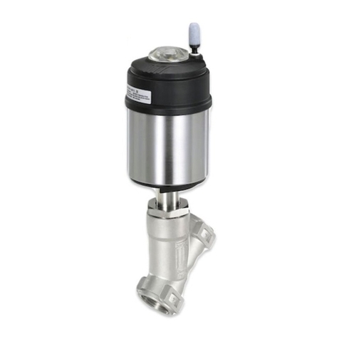
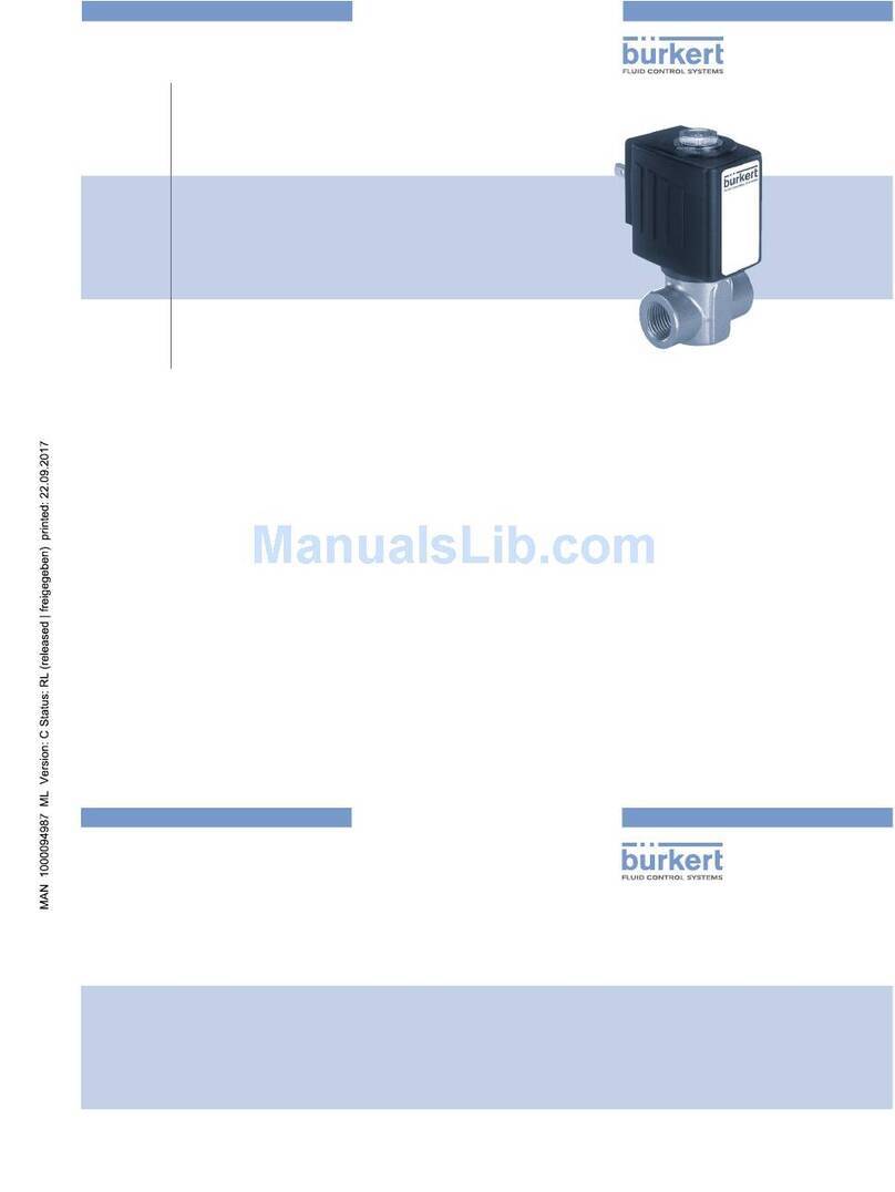
Burkert 8691 User manual

Operating Instructions
Bedienungsanleitung
Manuel d‘utilisation
Type 8691 Rev.2
Control Head
Steuerkopf
Tête de commande

We reserve the right to make technical changes without notice.
Technische Änderungen vorbehalten.
Sous réserve de modifications techniques.
© Bürkert Werke GmbH & Co. KG, 2017
Operating Instructions 1707/00_EU-ML_00810626 / Original DE

3
Control head Type 8691, Rev. 2
Table of conTenTs
1ABOUT THESE INSTRUCTIONS............................................................................................................8
1.1 Symbols........................................................................................................................................8
1.2 Denitionofterms........................................................................................................................ 8
2INTENDED USE ......................................................................................................................................9
3BASIC SAFETY INSTRUCTIONS .........................................................................................................10
4GENERAL INFORMATION.................................................................................................................... 11
4.1 Contact address.........................................................................................................................11
4.2 Warranty .....................................................................................................................................11
4.3 InformationontheInternet........................................................................................................11
4.4 Trademarks.................................................................................................................................11
5PRODUCT DESCRIPTION....................................................................................................................12
5.1 Structure.....................................................................................................................................12
5.1.1 Structure, integrated pilot air duct (21xx, Element) ....................................................12
5.1.2 Structure, external pilot air duct (20xx, Classic) .........................................................12
5.1.3 Variants .......................................................................................................................13
5.2 Function......................................................................................................................................13
6TECHNICAL DATA ................................................................................................................................14
6.1 Conformity..................................................................................................................................14
6.2 Standards ...................................................................................................................................14
6.3 Approvals ...................................................................................................................................14
6.4 Type label ...................................................................................................................................15
6.4.1 Type label standard ....................................................................................................15
6.4.2 UL type label...............................................................................................................15
6.4.3 UL additional label......................................................................................................15
english
Type 8691, Rev. 2

4
Inhaltsverzeichnis
6.5 Operatingconditions .................................................................................................................16
6.5.1 Fluidic data .................................................................................................................16
6.5.2 Electrical data .............................................................................................................16
6.5.2.1 Electrical data, IO-Link .........................................................................................16
6.5.2.2 Electrical data, büS.................................................................................................17
6.6 Mechanicaldata.........................................................................................................................17
6.6.1 Safety end positions...................................................................................................17
7MECHANICAL INSTALLATION .............................................................................................................18
7.1 Safetyinstructions .....................................................................................................................18
7.2 Installingdeviceswithintegratedpilotairduct(21xx,Element) .............................................18
7.3 Installingdeviceswithexternalcontrolairduct(20xx,Classic) ..............................................21
7.4 Aligning(turning)thedeviceandpositionofconnections.......................................................25
7.4.1 Turning the actuator, devices with hexnut ..................................................................25
7.4.2 Turning the actuator, devices without hexnut.............................................................27
7.4.3 Turning the device ......................................................................................................29
8PNEUMATIC INSTALLATION................................................................................................................30
8.1 Safetyinstructions .....................................................................................................................30
8.2 Connectingthedevicepneumatically.......................................................................................30
9ELECTRICAL INSTALLATION...............................................................................................................31
9.1 Safetyinstructionsforelectricalinstallation.............................................................................31
9.2 Connectingthedeviceelectrically,
IO-Link ........................................................................................................................................31
9.3 Connectingthedeviceelectrically,büS ...................................................................................32
10 START-UP .............................................................................................................................................33
10.1 Teachfunction:Determineendpositionsandsavethese,Rev.2...........................................33
10.1.1 Automatic teach function............................................................................................33
10.1.2 Manual teach function ................................................................................................35
10.2 SettingwithBürkertCommunicator..........................................................................................37
10.2.1 Connecting IO-Link device with Bürkert Communicator............................................37
10.2.2 Connecting büS device with Bürkert Communicator .................................................38
english
Type 8691, Rev. 2

5
10.3 IO-Link ........................................................................................................................................38
10.3.1 Information, IO-Link....................................................................................................38
10.3.2 Technicalspecications,IO-Link ................................................................................38
10.3.3 Interfaces, IO-Link ......................................................................................................39
10.3.4 Process data, IO-Link .................................................................................................39
10.3.4.1 Process input data (PDin) .......................................................................................39
10.3.4.2 Process output data (PDout) ..................................................................................40
10.3.5 Non-cyclic parameters (On-Request Data (ISDU)) .....................................................40
10.3.5.1 0x2000 Buerkert Device Description Object .........................................................41
10.3.5.2 0x2004 Device Status Object................................................................................41
10.3.5.3 0x2101 Locating function ......................................................................................42
10.3.5.4 0x2120 LED mode.................................................................................................42
10.3.5.5 0x2122 External color............................................................................................43
10.3.5.6 0x2C01 LED color for end positions......................................................................44
10.3.5.7 0x2C0B Control head settings ..............................................................................44
10.3.5.8 0x2C0C Teach function .........................................................................................46
10.3.5.9 0x2C0D CMD set-point .........................................................................................47
10.3.5.10 0x2C0E Diagnostics ..............................................................................................48
10.3.5.11 0x2C0F IO-Link SIO mode settings.......................................................................51
10.3.5.12 IO-Link-Events........................................................................................................52
10.4 büS..............................................................................................................................................54
10.4.1 Information, büS .........................................................................................................54
10.4.2 Interfaces, büS............................................................................................................54
10.4.3 Objects .......................................................................................................................54
10.4.3.1 0x2000 Buerkert Device Description Object .........................................................54
10.4.3.2 0x2001 Device Communication Object.................................................................55
10.4.3.3 0x2002UserCongurationObject ........................................................................56
10.4.3.4 0x2004 Device Status Object................................................................................56
10.4.3.5 0x2100 Get Mapping Function ..............................................................................57
10.4.3.6 0x2101 Locating function ......................................................................................57
10.4.3.7 0x2102BlockdownloadCongFunction ..............................................................57
10.4.3.8 0x2120 LED mode.................................................................................................58
10.4.3.9 0x2122 External color............................................................................................58
10.4.3.10 0x2200 Buerkert Driver Archive.............................................................................59
10.4.3.11 0x2220 EDS...........................................................................................................59
10.4.3.12 0x2400 Sensor Type ..............................................................................................59
english
Type 8691, Rev. 2

6
10.4.3.13 0x2420 No Measure Values...................................................................................59
10.4.3.14 0x2421 No Control Values.....................................................................................59
10.4.3.15 0x2422 No Calibration Values ...............................................................................59
10.4.3.16 0x2426 MPDO Inhibit Time bueS ..........................................................................59
10.4.3.17 0x242C Partner Status Object...............................................................................59
10.4.3.18 0x2500 GMV Position............................................................................................60
10.4.3.19 0x2501 GMV End Positions...................................................................................60
10.4.3.20 0x2540 GCV Setpoint............................................................................................61
10.4.3.21 0x2C01 LED colors................................................................................................61
10.4.3.22 0x2C0B XControl...................................................................................................62
10.4.3.23 0x2C0C Teach function .........................................................................................63
10.4.3.24 0x2C0D CMD set-point .........................................................................................65
10.4.3.25 0x2C0E Diagnostics ..............................................................................................65
10.4.3.26 0x2C0F IO-Link SIO mode settings.......................................................................68
10.4.3.27 0x2C11 MenuOptionBits .......................................................................................68
10.4.3.28 0x2C13 FactoryReset ............................................................................................68
10.4.3.29 Baud rates ..............................................................................................................68
10.4.3.30 Cyclic data..............................................................................................................68
11 OPERATION..........................................................................................................................................69
11.1 Displaydevicestatus,IO-LinkandbüS.................................................................................... 69
11.1.1 Pilot valve LED............................................................................................................70
11.1.2 Status LED, green and red..........................................................................................70
11.1.3 Device status display..................................................................................................70
11.1.3.1 Valve mode .............................................................................................................71
11.1.3.2 Valve mode + errors................................................................................................71
11.1.3.3 Valve mode + errors + warnings.............................................................................71
11.1.3.4 NAMUR mode ........................................................................................................73
11.2 Switchingthedevicemanuallywithpilotvalve ........................................................................73
12 MAINTENANCE ....................................................................................................................................75
12.1 Servicingtheairintakelter ......................................................................................................75
13 DEINSTALLATION................................................................................................................................. 76
13.1 Safetyinstructionsdeinstallation ..............................................................................................76
13.2 Deinstallation..............................................................................................................................77
english
Type 8691, Rev. 2

7
14 SPARE PARTS, ACCESSORIES...........................................................................................................78
14.1 Communicationssoftware......................................................................................................... 78
15 TRANSPORTATION, STORAGE, DISPOSAL........................................................................................79
english
Type 8691, Rev. 2

8
About these instructions
1 ABOUT THESE INSTRUCTIONS
The operating instructions describe the entire life cycle of the device.
→Keep these instructions ready to hand at the operation site.
Importantsafetyinformation.
▶Carefully read these instructions.
▶Observe in particular the safety instructions, intended use and operating conditions.
▶Persons, who work on the device, must read and understand these instructions.
1.1 Symbols
DANGER
Warnsofanimmediatedanger.
▶Failure to observe the warning will result in a fatal or serious injury.
WARNING
Warnsofapotentiallydangeroussituation.
▶Failure to observe the warning may result a fatal or serious injury.
CAUTION
Warnsofapossibledanger.
▶Failure to observe the warning may result in moderate or minor injuries.
NOTE
Warnsofdamagetoproperty.
▶Failure to observe the warning may result in damage to device or system.
Indicatesimportantadditionalinformation,tipsandrecommendations.
Referstoinformationintheseoperatinginstructionsorinotherdocumentation.
▶Designates an instruction for risk prevention.
→Designates a procedure which you must carry out.
Indicates a result.
1.2 Denition of terms
In these instructions the term “device” denotes the following device types:
Control head Type 8691 Rev. 2.
english
Type 8691, Rev. 2

9
Intended use
2 INTENDED USE
ThecontrolheadType8691Version2isdesignedtobemountedonpneumaticactuatorsofprocess
valvesforthecontrolofmedia.Thepermitteduidmediaarelistedinthetechnicaldata.
▶Use the device for its intended purpose only. Non-intended use of the device may be dangerous to
people, nearby equipment and the environment.
▶Correct transportation, correct storage as well as correct installation, commissioning, operation and
maintenance are essential for reliable and problem-free operation.
▶When using the device, observe the permitted data, operating conditions and application conditions.
This information can be found in the contractual documents, the operating instructions and on the type
label.
▶Use the device only in conjunction with third-party devices and components recommended and autho-
rized by Bürkert.
▶Do not use the device outdoors without protection from the weather.
▶In areas at risk of explosion, only use devices approved for use in those areas. These devices are
labeled with a separate Ex type label. For such use, note the information provided on the separate Ex
type label and the additional explosion-related information or separate explosion-related operating
instructions.
english
Type 8691, Rev. 2

10
Basic safety instructions
3 BASIC SAFETY INSTRUCTIONS
These safety instructions do not consider any contingencies or incidents which occur during installation,
operation and maintenance.
Theoperatorisresponsibleforobservingthelocation-specicsafetyregulations,alsowithreferencetothe
personnel.
DANGER
Riskofinjuryfromhighpressureanddischargeofmedium.
▶Beforeworkingonthedeviceorsystem,switchothepressure.Ventordrainlines.
DANGER
Riskofinjuryfromelectricshock.
▶Beforeworkingonthedeviceorsystem,switchothepowersupply.Secureagainstreactivation.
▶Observe applicable accident prevention and safety regulations for electrical equipment.
Topreventinjury,ensurethefollowing:
▶Secure device or system to prevent unintentional activation.
▶Only trained technicians may perform installation and maintenance work.
▶Perform installation and maintenance with suitable tools only.
▶Do not make any changes to the device and do not subject it to mechanical stress.
▶Operate the device only in perfect state and in consideration of the operating instructions.
▶Observe the general rules of technology.
▶Install the device according to the regulations applicable in the respective country.
▶Donotfeedcorrosiveorammablemediaintothedeviceconnections.
▶Donotfeedanyuidsintotheconnectionsofthedevice.
▶After the process is interrupted, restart in a controlled manner. Observe sequence:
1. Connect electrical or pneumatic power supply.
2. Charge the device with medium.
▶Observe intended use.
Thedevicehasbeendevelopedwithdueconsiderationgiventotheacceptedsafetyrulesandis
state-of-the-art.Nevertheless,dangeroussituationsmayoccur.
english
Type 8691, Rev. 2

11
General information
4 GENERAL INFORMATION
4.1 Contact address
Germany
Bürkert Fluid Control System
Sales Center
Chr.-Bürkert-Str. 13-17
D-74653Ingelngen
Tel. + 49 (0) 7940 - 10 91 111
Fax + 49 (0) 7940 - 10 91 448
E-mail: [email protected]
International
Contactaddressescanbefoundonthenalpagesoftheprintedoperatinginstructions.
Also in the internet at:
www.burkert.com
4.2 Warranty
The warranty is only valid if the device is used as intended in accordance with the specied application
conditions.
4.3 Information on the Internet
The operating instructions and data sheets for Bürkert products can be found on the Internet at:
www.burkert.com
4.4 Trademarks
The brands listed below are trademarks of the corresponding companies / associations or organizations.
Loctite Henkel Loctite Deutschland GmbH
english
Type 8691, Rev. 2

12
Product description
5 PRODUCT DESCRIPTION
5.1 Structure
Themodulardesignofthedevicesupportsvariouscongurationsandvariants.
Electrical connection:
circular plug-in connector
Exhaust air port, label: 3
Pressure limiting valve
Pilot air port, label: 1
Pilot valve LED
View without transparent cap:
Display device status:
high-power LEDs
Fastening screw
Status LED
Figure 1: Structure
5.1.1 Structure, integrated pilot air duct (21xx, Element)
The structure with integrated pilot air duct is optimized for mounting on process valves of the 21xx series
(Element).
Transparent cap
Body casing
Airintakelter
Fastening screw
Basic housing
Figure 2: Structure, integrated pilot air duct
5.1.2 Structure, external pilot air duct (20xx, Classic)
The structure with external pilot air duct is optimized for mounting on process valves of the 20xx series (Classic).
Transparent cap
Body casing
Airintakelter
Fastening screw
Basic housing
Pilot air outlet 2-1
Pilot air outlet 2-2
Figure 3: Structure, external pilot air duct
Sothatthepilotaircanbeexternallyconnectedtotheactuator,thisstructurehasadierentbasichousing..
english
Type 8691, Rev. 2

13
Product description
5.1.3 Variants
Communication possible via:
•IO-Link
•büS
5.2 Function
This device is capable of controlling single-acting and double-acting process valves.
The pilot valves can be manually overridden.
An analog, inductive sensor element provides feedback about end positions being reached. The teach
functionisusedforconguration.
Colored LEDs indicate the device status.
english
Type 8691, Rev. 2

14
Technical data
6 TECHNICAL DATA
6.1 Conformity
The device conforms to the EC directives as per the EC Declaration of Conformity (if applicable).
6.2 Standards
The applied standards, which are used to demonstrate conformity with the EC Directives, are listed in the EC
typeexaminationcerticateand/ortheECDeclarationofConformity(ifapplicable).
6.3 Approvals
The product is approved for use in zone 2 and 22 in accordance with ATEX directive 94/9/EC category 3GD.
Observe instructions on operation in the explosion-risk area. See additional explosion-related
information.
The product is cULus approved. Instructions on operation in the UL area see chapter “Electrical data”.
english
Type 8691, Rev. 2

15
Technical data
6.4 Type label
6.4.1 Type label standard
8691 büS
single act pilot 3,0
Pmax 7bar
Tamb -10 - +55°C Rev. 2
Ser.-Nr. 001000
00179024
D-74653 Ingelfingen
W14UN
Order number, manufacture code
Operatingvoltageoreldbuscontrol
Max. operating pressure
Type Control function, pilot valve
Barcode
Serial number, CE marking
Ambient temperature, version
Figure 4: Type label standard (example)
6.4.2 UL type label
8691 -E3-...-0
single act pilot 3,0 24V
Pmax 7bar
Tamb -10 - +55°C Rev. 2
Ser.-Nr. 001000
00179024
D-74653 Ingelfingen
W14UN
Order number, manufacture code
Features of the type code applicable to UL and ATEX
Max. operating pressure
Type Control function, pilot valve,
supply voltage pilot valve
Barcode
Serial number, CE marking
Ambient temperature, version
Figure 5: UL type label (example)
6.4.3 UL additional label
Type 4X enclosure
NEC Class 2 only
Supply voltage: 24 V Supply voltage device
Circuit with limited power
Degree of protection
Figure 6: UL additional label (example)
english
Type 8691, Rev. 2

16
Technical data
6.5 Operating conditions
Ambient temperature See type label
Degree of protection
Evaluated by manufacturer: IP65, IP67 as per EN 60529*
Evaluated by UL: UL type 4x Rating*
6.5.1 Fluidic data
Control medium Neutral gases, air
Quality classes as per ISO 8573-1
Dust content Class 7 Max. particle size 40 µm,
max. particle density 10 mg/m³
Water content class 3 Max. pressure dew point -20°C or
min. 10°C below lowest operating temperature
Oil content Class X Max. 25 mg/m³
Pressure range 3–7 bar
Temperature range -10 to +50 °C
Pilotvalveairowrate 250 lN/ min (for aeration and deaeration)
(QNn-valueaccordingtodenitionforpressuredropfrom7to6
bar absolute)
Connections Internal thread G 1/8 “
6.5.2 Electrical data
NOTE
ForvariantswithuULusapproval,pleasenote:
▶Only use circuits of limited power as per UL NEC Class 2.
6.5.2.1 Electrical data, IO-Link
Protection class 3asperDINEN61140(VDE0140-1)
Connection Circular plug-in connector M12 x 1, 4-pin, Port Class A
Operating voltage 18–30VDC(accordingtospecication)
Max. current consumption 135mA@18V(incl.inrushcurrentpilotvalvefor200ms)
Current consumption input during normal
operation
110mA@18V
(after current reduction,
pilotvalveafter200ms
and 1 end position reached)
* Only if cables, plugs and sockets have been connected correctly and in compliance with the exhaust air concept see chapter “Pneu-
matic installation”.
english
Type 8691, Rev. 2

17
Technical data
6.5.2.2 Electrical data, büS
Protection class 3asperDINEN61140(VDE0140-1)
Connection Circular plug-in connector M12 x 1, 5-pin
Operating voltage 18–30VDC(accordingtospecication)
Max. current consumption 120mA@18V(incl.inrushcurrentpilotvalvefor200ms)
Current consumption input during
normal operation
95mA@18V
(after current reduction,
pilotvalveafter200ms
and 1 end position reached)
6.6 Mechanical data
Dimensions See data sheet
Body material
exterior: PPS, PC, VA
Seal material
external:
internal:
EPDM
NBR
Stroke range of valve spindle 2–47 mm
6.6.1 Safety end positions
Safety end positions after failure of the electrical or pneumatic auxiliary power:
Actuator system Designation Safety end positions after failure of the auxiliary
power
electrical pneumatic
up
down
single-acting
control function A
down down
up
down
single-acting
control function B
up up
up
down
double-acting
control function I
down notdened
Table 1: Safety end positions
english
Type 8691, Rev. 2

18
Mechanical installation
7 MECHANICAL INSTALLATION
7.1 Safety instructions
DANGER
Riskofinjuryfromhighpressureanddischargeofmedium.
▶Beforeworkingonthedeviceorsystem,switchothepressure.Ventordrainlines.
WARNING
Riskofinjuryfromimproperinstallation.
▶Only trained technicians may perform installations.
▶Perform installations with suitable tools only.
WARNING
Riskofinjuryduetounintentionalactivationanduncontrolledstart-upofthesystem.
▶Secure system against unintentional activation.
▶Ensure that the system does not start up in an uncontrolled manner.
7.2 Installing devices with integrated pilot air duct (21xx,
Element)
Only for devices without preinstalled process valve.
Required attachment kit: ELEMENT Type 21xx
NOTE
Damagetothedeviceandthedrivewhenweldingweldedbodies.
Observe the following during installation on process valves with welded body:
▶Observe the installation instructions for the operating manual of the process valve.
▶Before installing the device, weld the process valve into the pipe system.
english
Type 8691, Rev. 2

19
Mechanical installation
1. Installing the switch spindle
Transparent cap
Actuator
Pilot air ports
(plug-in connectors with collets or
threaded bushings)
Position indicator
Figure 7: Installing the switch spindle (1), integrated pilot air duct
→Unscrew the transparent cap from the actuator.
→Unscrew position indicator from spindle extension.
→For variant with hose connector: remove the collets (white sleeves) from the pilot air ports.
Spindle extension
Guide element
Actuator cover
Lip seal
Puck
Switch spindle
Max. 5 Nm
Max. 1 Nm
O-ring
Figure 8: Installing the switch spindle (2), integrated pilot air duct
NOTE
Lipsealcanbedamagedifincorrectlyinstalled.
The lip seal is pre-mounted in the guide element and must be "locked into position" in the undercut.
▶When installing the switch spindle, do not damage the lip seal.
→Slide switch spindle through the guide element.
NOTE
Contaminationofthelipsealduetoscrewlockingpaint.
▶Do not apply any screw locking paint to the switch spindle.
→To secure the switch spindle, apply some screw locking paint (e.g. Loctite 290) in the threading of the
spindle extension in the actuator.
→Check that the O-ring is in the correct position.
→Screwguideelementinactuatorcover(tighteningtorque:max.5Nm).
→Screw switch spindle onto the spindle extension. A slot is provided on the top side (tightening torque:
max.1Nm).
→Push puck onto the switch spindle and lock into position.
english
Type 8691, Rev. 2

20
Mechanical installation
2. Attaching the form seal
→Pull the form seal onto the actuator cover (smaller diameter points upwards).
→Check that the O-rings are correctly positioned in the pilot air ports.
Before installing the device, remove the collets in the pilot air ports.
Pilot air ports
without collets
Form seal
Figure 9: Attaching the form seal
3. Installing the device
NOTE
DamageorfunctionaloutageofthePCB
▶Ensurethatthepuckliesatintheguiderail.
→Align the puck and device so that:
1. The puck rests in the guide rail of the device (see Fig. below).
2. Find the connection pieces of the device into the pilot air ports of the actuator (see second Fig.
below).
Guide rail
Puck
Figure 10: Aligning the puck
→Push the device without turning it onto the actuator until no gap is visible on the form seal.
NOTE
Damageormalfunctionduetoingressofdirtormoisture.
To observe the degree of protection IP65 or IP67:
▶Tighten fastening screws only with a tightening torque of max. 1.5 Nm.
→Attach device to the actuator using the two side fastening screws. In doing so, tighten the screws only
hand-tight (max. torque: 1.5 Nm).
english
Type 8691, Rev. 2
Other manuals for 8691
6
Table of contents
Other Burkert Control Unit manuals

Burkert
Burkert 6013 User manual

Burkert
Burkert 8695 User manual

Burkert
Burkert 0121 User manual

Burkert
Burkert 6524 User manual

Burkert
Burkert 2063 User manual

Burkert
Burkert 3323 User manual

Burkert
Burkert 2012 User manual

Burkert
Burkert 2080 User manual

Burkert
Burkert 0211 User manual

Burkert
Burkert 6650 User manual

Burkert
Burkert 3360 User manual

Burkert
Burkert 1066 User manual

Burkert
Burkert 2100 series User manual

Burkert
Burkert 0258 User manual

Burkert
Burkert 2702 User manual

Burkert
Burkert 7011 User manual

Burkert
Burkert Type 2000 User manual

Burkert
Burkert 5406 User manual

Burkert
Burkert 8835 User manual

Burkert
Burkert 3281 User manual