manuals.online logo
Brands
  1. Home
  2. •
  3. Brands
  4. •
  5. by.schulz
  6. •
  7. Bicycle Accessories
  8. •
  9. by.schulz Speedlifter 640119 User manual

by.schulz Speedlifter 640119 User manual

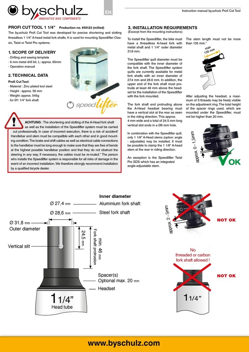
PROFI CUT TOOL 1 1/8" Production no. 640119 (milled)
The by,schulz Pro Cut Tool was developed for precise shortening and slotting
threadless 1 1/8" A-head metal fork shafts. It is used for mounting Speedlifter Clas-
sic, Twist or Twist Pro systems.
1. SCOPE OF DELIVERY
· Drilling and sawing template
· 6 mm metal drill bit, L: approx. 65mm
· Operation manual
2. TECHNICAL DATA
Pro Cut Tool:
· Material : Zinc plated tool steel
· Height : approx. 56 mm
· Weight: approx. 600g
· for Ø1 1/8“ fork shaft
To install the Speedlifter, the bike must
have a threadless A-head fork with
metal shaft and 1 1/8" outer diameter
28.6 mm.
The Speedlifter quill diameter must be
compatible with the inner diameter of
the fork shaft. The Speedlifter system
quills are currently available for metal
fork shafts with an inner diameter of
24.4 / 24.5 / 24.6 mm and 25.4 mm. In
addition, the upper end of the fork shaft
must protrude at least 46 mm above
the headset for the installation of the
Speedlifter with the fork mounted.
The fork shaft end protruding above
the A-Head headset bearing must
have a vertical slot at the rear as seen
in the riding direction. This approx. 4
mm wide and a total of 24.5 mm long
vertical slot ends in a Ø6 mm hole.
In combination with the Speedlifter quill,
1 1/8" A-Head stems (option: angle-ad-
justable) may only be installed together
with the supplied, slotted Speedlifter
A-Head reducing sleeve.
An exception is the Speedlifter Twist
Pro SDS which has an integrated an-
gle-adjustable stem.
This 1 1/8 "A-Head- Stems must be
possible to clamp at the rear (in riding
direction)! The stem length must not be
more than 135 mm."
The Speedlifter A-Head reducing
sleeve must have at least the same
available clamping height as that of the
stem.
After adjusting the headset, a maxi-
mum of 3 threads may be freely visible
on the adjustment ring. The total height
of the spacer rings used, which are
mounted under the Speedlifter, must
not be higher than 20 mm.
3. INSTALLATION REQUIREMENTS
(Excerpt from the mounting instructions)
Instruction manual by,schulz Pro Cut Tool - version from start of 2019
www.byschulz.com
ATTENTION : The shortening and slotting of the A-Head fork shaft as well
as the installation of the Speedlifter system must be carried out profession-
ally. In case of incorrect execution, there is a risk of accident! Handlebar and stem
must be compatible with each other and in good mounting condition.The brake and
shift cables as well as electrical cable connections to the handlebar must be long
enough to make sure that they are free of bends at the highest possible handlebar
position and that they do not obstruct the steering in any way. If necessary, the
cables must be re-routed." The person who installs the Speedlifter system is respon-
sible for all risks of damage in the event of an incorrect installation. We therefore
strongly recommend installation by a qualied bicycle dealer.
24,5 mm
Optional max. 20 mm
Ø 28,6 mm
Ø 24,4 mm
Ø 24,6
mm
mm
Ø 25,4 mm
Ø24,5
Inner diameter
aluminium fork shaft
Steel fork shaft
Outer diameter
Vertical slot
Head tube
fork shaft protrusion
Distance ring(s) / spacer
Headset
46 mm
approx. 2 - 5mm
NOT OK
NOT OK
No
threaded or carbon
fork shaft allowed !
approx. 0 - 1,5mm
EN
4.4 (Fig. 4.4)
Using a metal saw, saw off the fork
shaft to the specied length through
the horizontal slot in the tool.
4.5 (Fig. 4.5)
Now use the saw to saw diagonally
from above along the right and left
edges of the vertical saw guide slot
into the existing drill hole. This cre-
ates an approx. 4 mm wide, vertical
slot in the fork shaft, which ends in
the 6 mm drill hole.
4.6 (Fig. 4.6)
Carefully remove sharp edges from
the saw cuts and the bore inside and
outside with a half-round metal le.
Remove the cloth and the resulting
sawdust carefully. Clean and grease
the inside of the fork shaft. Now you
can install the Speedlifter.
Reverse option: To use the slotted
fork again with a normal A-head stem,
the by.schulz Speedlifter Ready Kit
reinforcement sleeve with the correct
spacer must be used.
5. MAINTENANCE / CARE
Clean the Pro Cut Tool after each use
and free it from saw and drill particles.
Store the Pro Cut Tool in a dry and
clean place.
4. TOOL USAGE
Info: If no stem and no A-Head claw are mounted yet, you can ignore the fol-
lowing section!
Unscrew the existing A-Head end cap. Remove the A-Head claw basically upwards
with the stem installed. Loosen the stem and remove all unneeded spacer rings.
4.1 (Fig. 4.1)
Align the front wheel standing to the
ground exactly parallel to the frame.
Place the 2 mm spacer (only sup-
plied with production no. 641117) on
the headset bearing or the spacer
rings above it and slide the ProCut
tool (imprint "Top" facing upwards)
over the fork shaft onto the 2 mm
spacer. Align the tool so that the 6
mm drill guide (imprinted "REAR")
points backwards towards the sad-
dle and the imaginary center line of
the lengthwise slot is exactly aligned
with the driving direction.
4.2 (Fig. 4.2)
Press the tool rmly against the
headset with the 2 mm spacer
(only for production no. 641117) and
secure it with the integrated Allen
screw (5-6 Nm). Important: Tool and
headset must be free of play!
Tip: Place a piece of cloth around
the area of the headset and the
front area of the wheel to protect the
sensitive bearing area from drilling
and sawdust.
4.3 (Fig. 4.3)
Drill the 6 mm hole into the fork shaft
with the included metal drill bit using
the drill guide.
Fig. 4.1
Fig. 4.3
Fig. 4.2
Fig. 4.4
Fig. 4.5
Fig. 4.6
Instruction manual by,schulz Pro Cut Tool - version from start of 2019
by,schulz © 2023 No reprints, translations or copies of any kind allowed without the prior written approval of by,schulz GmbH. Subject to technical alterations, errors and misprints excepted. Used photos can
vary from the original product. by,schulz GmbH, Saarbrücken/Germany. M-PCT-after-20230329-EN / AN-10564
by.schulz GmbH
Bühler Str. 121
D-66130 Saarbrücken
GERMANY
Tel : +49(0)681-95 97 25 0
Fax : +49(0)681-95 97 25 20
info@byschulz.com
www.byschulz.com
www.byschulz.com
www.youtube.com
Safety instructions and warranty/guarantee:
see detailed operating instructions on
www.byschulz.com
Operating instructions
available for download:
Installation videos
available under :
ATTENTION: The vertical slot in the fork shaft must be centered at
the rear in the driving direction. If a spacer ring (maximum 20 mm)
is used, the height to be shortened changes accordingly.
The fork shaft must be undamaged inside and outside after shortening
and slotting with the Pro-Cut tool.
for steel fork shafts
inner Ø 25,4mm
for aluminium fork shaft
inner Ø 24,4 / 24,5 / 24,6mm
More about
the product
Other by.schulz Bicycle Accessories manuals

by.schulz e-Bikelifter BM-60 User manual

by.schulz

by.schulz e-Bikelifter BM-60 User manual

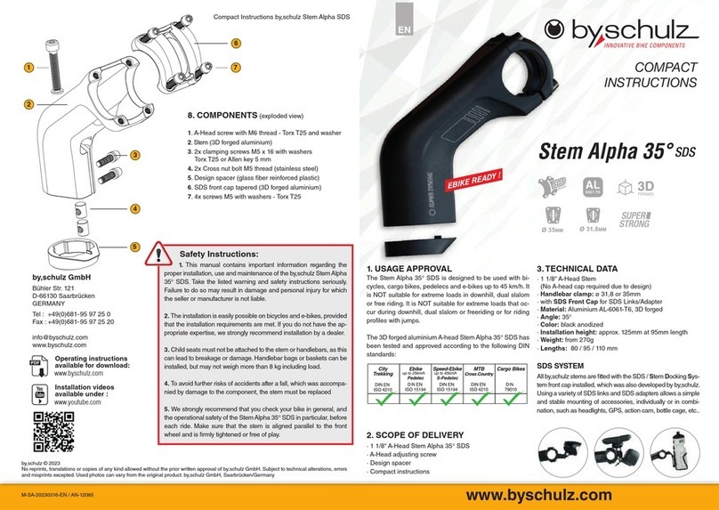
by.schulz Stem Alpha 35 SDS Installation instructions

by.schulz

by.schulz Stem Alpha 35 SDS Installation instructions

by.schulz D.1 Ri User manual

by.schulz

by.schulz D.1 Ri User manual

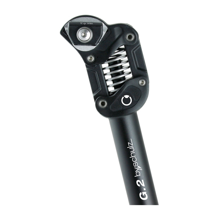
by.schulz G.2 ST Manual

by.schulz

by.schulz G.2 ST Manual

by.schulz 650123 User manual

by.schulz

by.schulz 650123 User manual

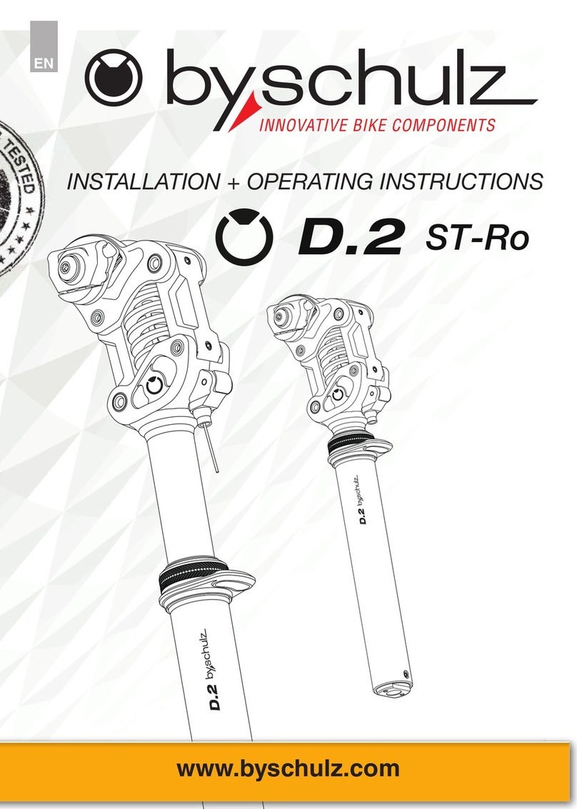
by.schulz D.2 ST-Ro User manual

by.schulz

by.schulz D.2 ST-Ro User manual

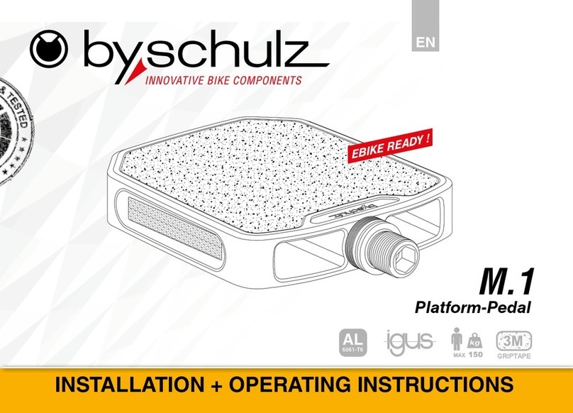
by.schulz M.1 User manual

by.schulz

by.schulz M.1 User manual

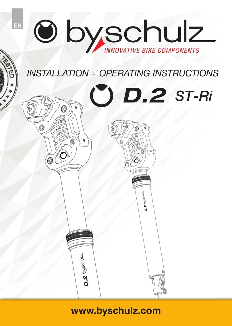
by.schulz D.2 ST-Ri User manual

by.schulz

by.schulz D.2 ST-Ri User manual

by.schulz Stem Alpha +10 SDS Installation instructions

by.schulz

by.schulz Stem Alpha +10 SDS Installation instructions

by.schulz G.2 ST User manual

by.schulz

by.schulz G.2 ST User manual

Popular Bicycle Accessories manuals by other brands

Performance ViewPoint Single Pro owner's manual

Performance

Performance ViewPoint Single Pro owner's manual

Specialized FireBalls Comp manual

Specialized

Specialized FireBalls Comp manual

Miche SUPERTYPE T DX Manual of maintenance and use

Miche

Miche SUPERTYPE T DX Manual of maintenance and use

Hyena LCD Compact EX product manual

Hyena

Hyena LCD Compact EX product manual

ROSE Bikes 2335609 owner's manual

ROSE Bikes

ROSE Bikes 2335609 owner's manual

Silva COMMUTE Product information

Silva

Silva COMMUTE Product information

Bosch Performance Line owner's manual

Bosch

Bosch Performance Line owner's manual

RIESE & MULLER VBK0192 owner's manual

RIESE & MULLER

RIESE & MULLER VBK0192 owner's manual

Miche SWR RC38DX OLT Manual of maintenance and use

Miche

Miche SWR RC38DX OLT Manual of maintenance and use

Vetta PathFinder II Wireless Quick start manual

Vetta

Vetta PathFinder II Wireless Quick start manual

Magura JULIE hp Workshop manual

Magura

Magura JULIE hp Workshop manual

WHEELSWING VOLT 1 user manual

WHEELSWING

WHEELSWING VOLT 1 user manual

Shimano Alfine S7000 Series Dealer's manual

Shimano

Shimano Alfine S7000 Series Dealer's manual

ACID PACK PRO 9/15 quick start guide

ACID

ACID PACK PRO 9/15 quick start guide

UNLEAZHED UNSPLASH M02 Assembly instructions

UNLEAZHED

UNLEAZHED UNSPLASH M02 Assembly instructions

Ortlieb QUICK RACK Assembly instructions

Ortlieb

Ortlieb QUICK RACK Assembly instructions

SCIWIL M61 user guide

SCIWIL

SCIWIL M61 user guide

Busch+Müller Mu E 332ALK instruction manual

Busch+Müller

Busch+Müller Mu E 332ALK instruction manual

manuals.online logo
manuals.online logoBrands
  • About & Mission
  • Contact us
  • Privacy Policy
  • Terms and Conditions

Copyright 2025 Manuals.Online. All Rights Reserved.