by.schulz G.2 ST User manual

INSTALLATION + OPERATING INSTRUCTIONS
ST
Parallel suspension seatpost

INTRODUCTION
Thank you for purchasing a by.schulz product. Please
read the manual carefully before installation and usage.
If you have any further question please contact your spe-
cialist dealer. Have a great ride!
TABLE OF CONTENTS Page
1. Usage Approval 02
2. Scope of delivery 02
3. Safety Instructions 02
4. Technical Data 03
5. Function 03
6. Components 04-05
7. Spring Elements 05
8. Installation Requirements 06
9.1 Seatpost Installation 06
9.2 Saddle Installation and Adjustments 07
10. Changing the Spring Element 08-09
11. Maintenance and Care 10
12. Warranty 10
1. USAGE APPROVAL
By,schulz products (e.g. the speedlifter system) are avail-
able on the bike market for more than 25 years, and we
are an international supplier for bike manufacturer, whole-
sale dealers and dealers. Multiple components are stan-
dard equipment on bicycles, cross country MTB, pedelecs
and e-bikes.
The G.2 ST / LT seatpost is suited for use in bicycles, cargo
bikes, pedelecs and e-bikes up to 45 km/h. It is NOT us-
able for extreme stress such as downhill riding, dual slalom,
free-riding or riding with jumps.
The G.2 ST / LT seatpost is forged from aluminium and is
tested and approved according to the DIN norm:
2. SCOPE OF DELIVERY
· Seatpost
· Mudcover (not included, if original equipment)
· Operating instructions
3. SAFETY INSTRUCTIONS
Before the rst ride:
We strongly recommend checking the overall tness of the
bicycle and the operational safety of the seatpost before
each ride.
First check that the saddle is rmly attached to the seat
clamp. Also make sure that the seatpost tube is rmly at-
tached to the bicycle frame without any slack. It must be
clamped in the desired position so that it cannot be turned
or shifted inside the seatpost tube. Please note that the
minimum insertion depth of the seatpost is 90 mm.
1. This instruction contains important informa-
tion on the proper installation, use, and main-
tenance of the G.2 ST / LT seatposts. Please take
the listed warnings and safety instructions seriously.
Otherwise personal injury and material damage may
occur, for which the dealer or manufacturer is not li-
able.
2. The installation is easily possible on bicycles and
e-bikes, but pay attention to the Installation Requi-
rements (see page 6) beforehand. If you do not have
the appropriate expertise, we strongly recommend
installation by a specialist dealer.
3. Child seats, trailer couplings or luggage racks may
not be attached to the G.2 ST / LT seatposts because
this can lead to breakage or damage.
4. We recommend to always use the protective cover
made from neoprene to prevent soiling. Be sure to
use the mudcover to cover the spring mechanism if
a child seat is attached behind the seatpost. Without
the cover, there is a risk of injury to children's hands!
5. To avoid further accident risks after a fall with da-
mage, the seatpost must be replaced.
02/12
This symbol indicates an important screw
connections, and the screw must be tightened
with an specic tightening torque. The correct tigh-
tening torque is either listed on the part itself or in the-
se operating instructions. A torque wrench is required
for proper installation Screws that are not tightened
correctly, may loosen or break without warning. This
may cause a fall and lead to personal injuries and
material damage.
Installation + Operating Instructions G.2 ST / LT Seatpost

4. TECHNICAL DATA
· Parallel suspension seatpost
· Material: 3D forged aluminium AL-6061-T6, AL-6066-T6
· Designed for a maximum rider weight of 150 kg
· IGUS high performance polymer plain bearings/stainless steel pins
· Spring elements in 5 different strengths, selectable
according to rider weight and easily exchangeable
· Seat clamp with ne adjustment and robust grating
· For saddle rail tubes with 7mm diameter, 8 mm is optionally
available
Modell: G.2 ST
· Installation height ca. 100mm
· Spring element Length ca. 72mm
· Suspension travel ca. 30mm
· Offset ca. 17mm
· Tube diameter ø25.4 - 34.9mm
· Lengths 350 - 450mm / shortenable
· Weight ab ca. 600g
Modell: G.2 LT
· Installation height ca. 130mm
· Spring element Länge ca. 102mm
· Suspension travel ca. 50mm
· Offset ca. 19.5mm
· Tube diameter ø26.6 - 34.9mm
· Lengths 380 - 670mm / shortenable
· Weight ab ca. 750g
5. FUNCTION
The parallelogram suspension seatpost is designed to of-
fer the highest level of riding comfort, and this in the city as
well as in rough terrain.The suspension is progressive, i.e.
the system responds sensitively to light shocks and with
increasing spring resistance to hard impacts.
When compressing, the G.2 ST parallelogram suspension
seatpost moves up to 18 mm backwards and 22 mm down-
wards, and the G.2 LT up to 33.5 mm backwards and ap-
prox. 40.5 mm downwards.
Due to the use of a heavy-duty at wire steel spring as well
as technical elastomers in the centre of the spring and on
the inside of the arms, even hard impacts (e.g. deep pot-
holes) do not lead to blocking of the suspension.
Additionally the backward extension movement is damped
by the hemispherical elastomers in the head and base
part. In order to adjust the G.2 ST / LT to the weight of the
rider and the riding style, easily interchangeable spring
elements with different spring stiffness and dampers are
available.
03/12
Installation + Operating Instructions G.2 ST / LT Seatpost
Riding direction
ca. 100mm
ca. 30mm
ca. 50mm
ca. 130mm
Available sizes as of Nov. 2022. Subject to change w/o notice.
x= Rider weight up to 150kg x= Rider weight up to 130kg
= with internal thread for pull-out stop ring
Length Ø G.2 LT seatpost
[mm] 25.4 26.4 26.6 26.8 27.2 30.6 30.9 31.6 33.9 34.9
380 x x x
480 xxx
670 x
Length Ø G.2 ST seatpost
[mm] 25.4 26.4 26.6 26.8 27.2 30.6 30.9 31.6 33.9 34.9
300 x
350 xxxxxxx
400 xx
450 xxx

04/12
Exploded view G.2 ST (and G.2 LT) March 2018, may change at any time
Installation + Operating Instructions G.2 ST / LT Seatpost
6 .1
33.1
1.4 1.3 1.2 1. 1 2
7.1
3.2
3.2
2.1
7
4.2
4.3
6.2
8
5.1
5.2
1
4.1

05/12
6. COMPONENTS
SEAT CLAMP :
1. Seat clamp- assembled
1. 1 Seat clamp base with toothing
1. 2 Seat clamp pressure spring
1. 3 Seat clamp upper part
1. 4 Seat clamp screw M6, Torx T25 with washer
(optional: Allen key 5 mm)
HEAD :
2. Head base part with ne toothing
2.1 Internal backstroke damper
SPRING ARM :
3. Spring arm with spring plate (2x)
3.1 Elastomer - stop damper (2x)
3.2 Grub screw M5 (4x) - Allen key 2.5 mm
SPRING ELEMENT :
4.1 Flat wire steel spring
4.2 Elastomer – central damper
4.3 Spring end-cap with centering pin (2x)
SMALL PIVOT BEARING :
5.1 Igus plain bearing, inner Ø 6.5 mm, (4x)
5.2 Stainless steel pin, outer Ø 6.5 mm, (2x)
LARGE PIVOT BEARING :
6.1 Igus plain bearing, inner Ø 8 mm, (4x)
6.2 Stainless steel pin, outer Ø 8 mm, (2x)
SEATPOST BODY :
7. Seatpost tube with base part
7. 1 Internal backstroke damper
8. Mudcover / Protective Cover
7. SPRING ELEMENTS
For the parallelogram suspended G.2 seat post, different
strong spring elements are offered which can be easily
and quickly changed (see page 08-09). The following table
will help you in the choice of the right suspension element,
considering the rider weight, riding position and riding pro-
le into the decision.
Rider weight =
body weight of the rider + additional weight (e.g. backpack)
Spring elements are available in soft, medium, standard,
hard and extra hard for riders with a body weight ranging
from 45 to 150 kg. The spring elements are marked with a
color code indicating their properties.
Only use the original by,schulz suspension elements for
the G.2 seatpost. Using third-party components may inter-
fere with the function of the seatpost and may cause ac-
cidents, personal injuries, material damages and will void
the claims from liability for material defects and warranty!
(see page 11).
Installation + Operating Instructions G.2 ST / LT Seatpost
Length 102mm
G.Series LT Spring Element
Length 72mm
G.Series ST Spring Element
RED
GREEN
BLUE
YELLOW
BLACK
COLORCODE HARDNESS GRADE

8. INSTALLATION REQUIREMENTS
· Please make sure that the inner diameter of the seat tube
of the bicycle frame and the outer diameter of the G.2 ST / LT
seatpost are the same.
· Different dimensions can lead to clamping failure as well
as accidents and material damage or personal injury.
· With a reducing sleeve, the tube diameter of the seat
post can be adapted to the dimension of the seat tube.
To adapt the seat post tube, we recommend the dou-
ble-slotted aluminium reducing sleeve from by,schulz with
a height of 120mm provided for this purpose. The following
diameters are available:
· When using a third party reduction shim please make sure
that it is it out of aluminium, has a minimum length of 90 mm
and is completely inserted into the seat tube.
· Always use the appropriate saddle clamps for the corre-
sponding saddle frame. Saddle clamps for saddle rails with
a diameter of 7 mm are installed by default. 8 mm saddle
clamps can also be installed. Never combine 8 mm saddle
clamps with 7 mm saddle rails or vice versa.
Note: Saddles with oval rails must not be installed.
9. INSTALLATION
9.1 Seatpost installation
Note before installation:
In order to avoid scratching the seatpost tube all sharp
edges and burrs in the opening of the seat tube of the bike
frame must be removed and the area must be cleaned.
For metal frames we strongly recommend greasing the
inside of the upper seat tube (the reducer sleeve should
also be greased when used). This ensures problem-free
height adjustment of the seatpost later.
Do NOT use grease for frames made of carbon bre rein-
forced plastics (Carbon). Instead use a special assembly
paste for carbon parts and frames.
1. Please make sure that the insertion depth of the seat-
post tube is not less than the minimum value of 90 mm. A
marking on the uncut seat post tube illustrates this. This
marking (STOP MIN: INSERT) is located on the back of
the seatpost below the extension scale. Above the scale
you will nd the production series no.
Minimum-insert Serial No.
2. Especially with small-sized bicycle frames or frames
with pre-equipped bottle cages, it might be impossible to
insert the seatpost far enough into the seat tube of the
bicycle. In this case the seatpost tube of the G.2 ST / LT
can be shortened. We explicitly recommend that you com-
mission a specialist dealer with this work. After shortening
the seatpost tube always make a new marking for the 90
mm minimum insertion depth.
This marking must NOT be in the form of a notch! The
seat post tube must never be shortened below a minimum
length of 90 mm..
3. After insertion into the seat tube of the bicycle, the seat-
post is fastened by correctly tightening the clamping screw
or closing the quick release lever of the seat tube clamp
(please also refer to the bicycle manufacturer's recom-
mendations).
9.2 Saddle installation
1. Loosen the saddle clamp screw of the left and right saddle
clamp (Fig.9.2.1) until the gap of the holding groove is ap-
prox. 9 mm (Fig.9.2.2). When unscrewing the saddle clamp
screw, the saddle clamp opens due to the spring pressure of
the concealed spring without twisting.
06/12 Installation + Operating Instructions G.2 ST / LT Seatpost
Ø 34,9 > 31,6
Ø 34,9 > 30,9
Ø 33,9 > 31,6
Ø 33,9 > 30,9
Ø 31,6 > 27,2
Ø 30,9 > 28,0
Ø 30,9 > 27,2
Ø 30,6 > 27,2
Ø 30,2 > 27,2
Ø 30,0 > 27,2
120mm
Abb. 8.1
min.
35mm
ca. 34mm

07/12
Installation + Operating Instructions G.2 ST / LT Seatpost
Abb.9.2.1 Abb.9.2.2
T25
2. Insert the saddle rail from above optionally into the right
or left holding groove of the saddle clamps. (Fig.9.2.3)
Abb.9.2.3 Abb.9.2.4
3. Then push the seat frame into the groove of the oppo-
site seat clamp (Fig 9.2.4). You must overcome a slight
pressure point until the seat frame audibly engages.
4. Tighten the two saddle clamps until the frame is loosely
held in them. The saddle should still easily be movable
by hand in the lengthwise direction, and the angle can be
adjusted in the detent of the saddle clamps.
9.3 Seat Angle / Seating Position Adjustments
1. The saddle clamps and the head of the G.2 seatposts
are equipped with a forged ne toothing.This allows you to
individually adjust the desired saddle angle. You can also
move the saddle rail lengthwise (Fig. 9.2.5). The saddle
must not be clamped in the curved area, but only in the
straight area of the rail!
Abb.9.2.5
Mounting example
Riding direction
2. Once you have found your seat position, tighten the
saddle clamp bolts rmly with a torque wrench in com-
bination with a Torx T25 to a torque of 12 - 14 Nm (Fig.
9.2.7). Compliance with this value is relevant to safety!
The correct tightening torque is indicated on both saddle
clamps of the prop (Fig. 9.2.6).
Abb.9.2.6
T25
Abb.9.2.7
The M6 Torx T25
saddle clamp screws
(optional: 5mm Allen
screw) must be tightened
to 12-14 Nm with a torque
wrench.
3. To adjust the desired seat height, open the clamping
screw or the quick-release lever of the saddle clamp. Move
the saddle to the desired position and retighten the screw
to the specied torque or close the quick-release lever.
4. The spring mechanism of the seat post already dips a
little lower due to the load when sitting up. Therefore, you
can x the saddle approx. 10 mm higher to compensate for
the dipping of the spring element. Your specialist dealer
will be happy to advise you on this.
9.4 Saddle Removal
1. In order to remove the saddle rst loosen the two seat
clamp screws. The clamping mechanism opens automati-
cally because of the pressure of the internal saddle clamp
spring.
2. When the opening width of the holding groove is ap-
prox. 9 mm, pull the saddle rail upwards out of the saddle
clamp. A slight pressure point must be overcome for this.
Note : make sure the saddle is rmly attached to
the seat clamps.A loose saddle can lead to accidents,
personal injuries or material damage.

10. CHANGING THE SPRING ELEMENT
10.1 Removal of the Spring Element
1. Open the M5 grub screw of the large pivot bearing in the
rear arm of the G.2 ST / LT seatpost with a 2.5 mm Allen
key. Turn the screw counterclockwise until it protrudes ap-
prox. 2 mm from the arm. Then use a proper tool to push
the 8 mm stainless steel axle out of the bearing.
2. Now open the parallelogram mechanism by pulling the
rear spring arm upwards by hand. The entire upper part of
the seat post tilts forward in the direction of travel.
3. Lift up the rear spring arm upwards in the small piv-
ot bearing until the spring element is released from the
adjustment in the spring plate. Now you can remove the
spring element by hand. (see Fig. 10.1.3).
Use this opportunity to check the condition of the elasto-
mer damper elements in the seat post base, spring arms
and head of the G.2, and to clean the inner area of the
spring element mount!
08/12
Note : We recommend keeping the G.2 ST / LT se-
atpost mounted in the bicycle frame when changing
the suspension element. The saddle does not have to be
removed either.
Note : Use the changing the spring for a visual inspec-
tion of the elastomer damping elements in the seatpost
base, the spring arms and the head of the G.2 ST/ G.2 LT
seatpost.The spring mechanism must be opened complete-
ly in order to check the backstroke damper. Clean the inner
area of the head and body if necessary.
Installation + Operating Instructions G.2 ST / LT Seatpost
stainless steel pin
grub screw
Fig. 10.1. 2
Fig. 10.1.1
Fig. 10.1. 3

09/12
Installation + Operating Instructions G.2 ST / LT Seatpost
Fig.10.2.1
centering pin
Fig. 10.2.2
Fig. 10.2.3
10.2 Installation of the spring element
1. Place the original ST / LT spring element in the parallel-
ogram mechanism by hand. Press the centering pin of the
spring element into the corresponding hole of the spring
arm plate of the front spring arm.
2. Now push the rear spring arm back downwards to make
the adjustment of the spring element between the arms.
The second centering pin of the spring element audibly
engages i the hole of the spring arm plate of the rear
spring arm.
3. Fold the entire parallel suspension mechanism in the
small pivot bearing back downwards to the stop. Then re-
insert the 8 mm pin. Make sure the pin is correctly aligned
with all holes.
The M5 screw must have sufficient blue thread locking ad-
hesive, apply new adhesive if necessary. Refasten the M5
headless screw and tighten it with a torque of 2,5 Nm. The
pin is now safely fastened by its centering groove.
Please check the correct t of all components before the
rst ride with the new spring.
Note : The M5 grub screw must be inserted with
medium strength thread locking adhesive, and
must not loosen on their own under any circumstanc-
es after tightening. Check if the grub screw is still
tightened with a torque of 2,5 Nm after approx. 1-2
hours of operation. Use a torque wrench with a 2.5
mm Allen head attached.

11. MAINTENANCE / CARE / CLEANING
The G.2 ST / LT suspension seatpost is based on a well
thought out concept and consists of high-quality compo-
nents. This guarantees you a long riding pleasure with reg-
ular maintenance.
After the rst 3 months or approx. 250 km of riding, check all
screws for correct tightening torques. Have this check car-
ried out and documented by a specialist dealer every year
thereafter, or after approx. 2000 km. To ensure trouble-free
use of the G.2 support, all bearing pivot points should also
be cleaned and lubricated during this check.
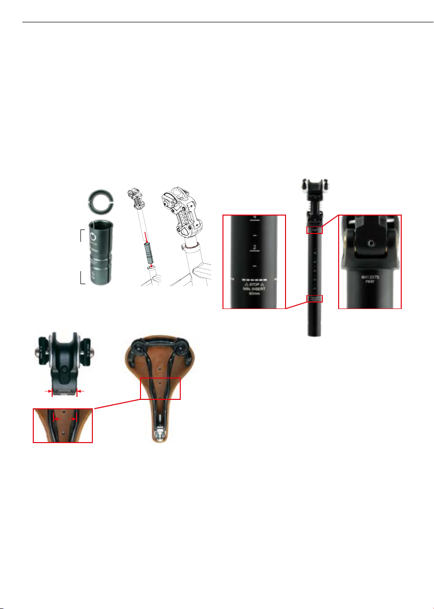
The supplied protective and safety cover made of neoprene
effectively prevents dirt build-up (mud, sand, etc.) and thus
ensures low cleaning and maintenance effort. We recom-
mend the permanent use of the neoprene sleeve.
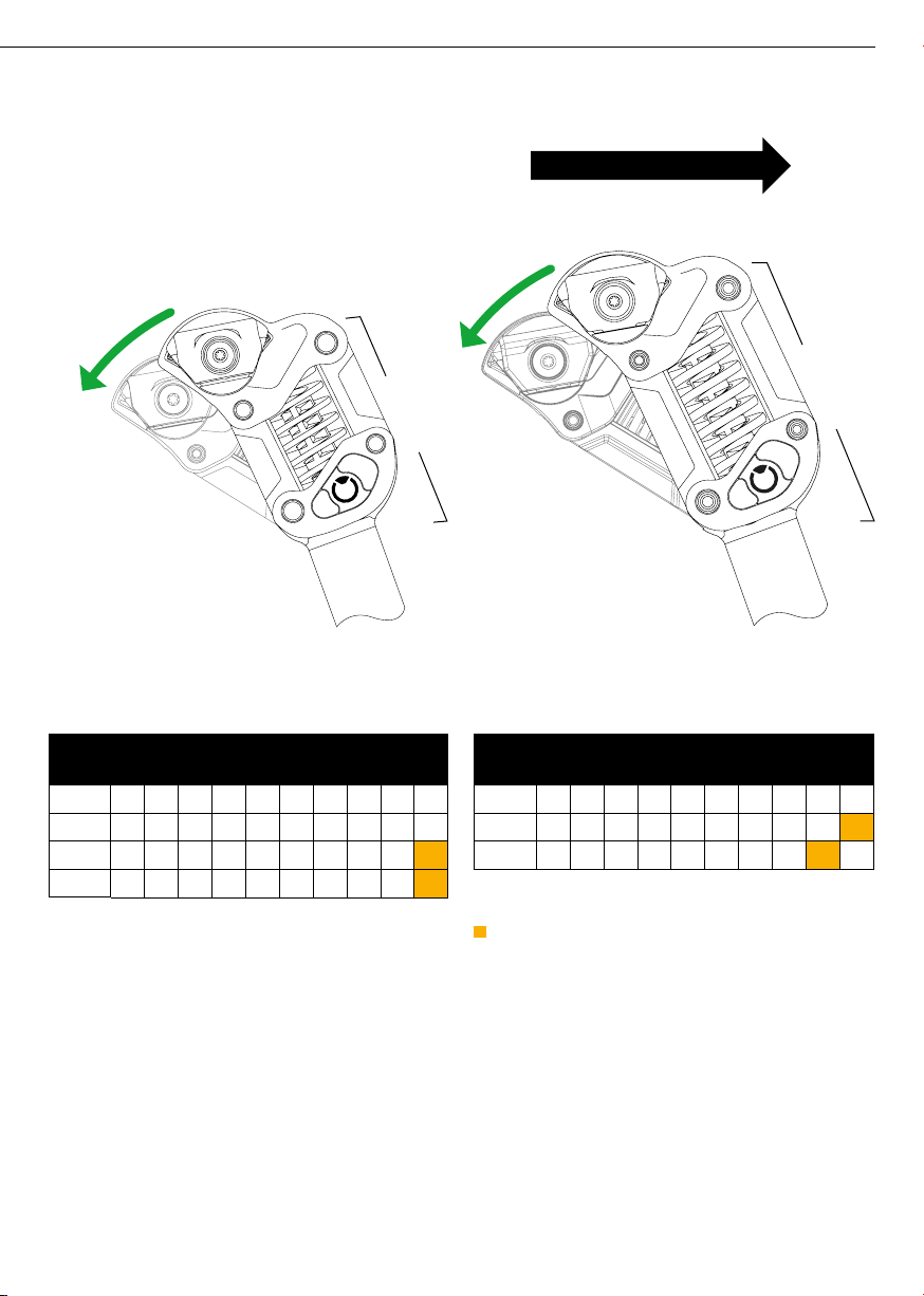
Keep the parallelogram mechanism of your G.2 ST / LT
seatpost and the bearings free of dirt and mud and clean
them regularly.
Tough dirt can usually be removed with warm water and
standard dishwashing detergents. For the care of the bear-
ing pivots, we recommend the manufacturer Ballistol (uni-
versal spray). Do not use a steam cleaner or harsh cleaning
agents such as acetone, trichloroethylene or methylene for
cleaning, as these cleaning agents attack the components,
elastomers and bearings.
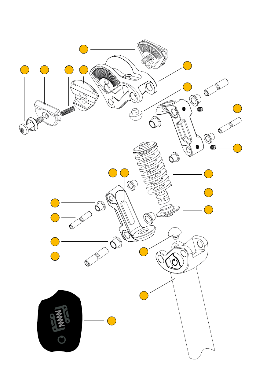
If you disassemble the seat post completely for cleaning or
maintenance purposes, it is recommended to lubricate the
bearings and axles with acid- and resin-free bearing grease
when reassembling.
When cleaning the G.2 seat post, look for damage, defor-
mation or other changes to the components. If you have
any questions regarding operational safety, your dealer will
be happy to help you.
12. WARRANTY / GUARANTEE
The following conditions, which describe the requirements
and scope of our warranty service, do not affect the warran-
ty obligations of the seller under the purchase contract with
the end user. For the processing of a warranty claim, the
proof of purchase with the date of purchase and delivery
must be submitted in each case.
A warranty obligation is not triggered by minor deviations
from the target condition, which are insignicant for the val-
ue and usability of the product.
Please keep the proof of purchase. Your specialist dealer
or source of supply is the contact person in the event of a
complaint.
For the by,schulz seat post type G.2 ST / LT we provide
warranty according to the following conditions / points:
1. We will remedy free of charge defects which are demon-
strably based on a material and/or manufacturing defect,
if these are reported to the rst end user immediately after
detection and within 24 months after delivery. If the defect
becomes apparent within 6 months of delivery, it shall be
presumed to be a material or manufacturing defect.
2. No guarantee can be given if the defects in the product
are due to transport damage for which we are not respon-
sible, improper assembly, misuse, non-standard use, lack
of maintenance or care or failure to observe operating or
assembly instructions. Excluded are damages and their
consequences caused by improper assembly, modication
of the original parts, accidents, overloads (downhill, jumps,
competitions etc.).
3. The person who mounts the by,schulz G.2 ST / LT seat-
post bears full responsibility for the assembly, compatibility
and condition of the mounting parts. The warranty claim ex-
pires if repairs or interventions are carried out by persons
who do not have sufficient professional knowledge, or if
our product is provided with spare parts, supplements or
accessories that are not original parts and thus cause a
defect.
4. In the event of a warranty claim, if we refuse or fail to
remedy the defect, a replacement of equal value will be de-
livered free of charge within the above-mentioned period.
5. Warranty services do not cause an extension of the war-
ranty period, nor do they set a new warranty period in mo-
tion. The warranty period for installed spare parts ends with
the warranty period for the product.
6. Further or other claims, damages caused by misuse are
excluded - as far as a liability is not mandatorily ordered
by law.
7. These warranty conditions apply to products purchased
in Germany. For by,schulz products purchased abroad, the
warranty conditions issued by our respective country repre-
sentative shall apply.You can request these from the dealer
from whom you purchased the product.
Our customer service and service partners will be happy to
assist you even after the warranty has expired.
010/12 www.byschulz.com

NOTES :
11/12
Installation + Operating Instructions G.2 ST / LT Seatpost

www.byschulz.com
M-G2-20230214-EN / AN-10890-EN
by,schulz GmbH
Bühler Straße 121
66130 Saarbrücken
Tel : +49(0)681-95 97 25 0
Fax : +49(0)681-95 97 25 20
info@byschulz.com
www.byschulz.com
by.schulz © 2023
No reprints, translations or copies of any kind allowed without the prior written approval of by.schulz GmbH. Subject to technical alterations, errors
and misprints excepted. Used photos can varying from the original product
www.byschulz.com
www.youtube.com
Operating instructions
available for downloald:
Installation videos
available under :
Other manuals for G.2 ST
1
This manual suits for next models
1
Table of contents
Other by.schulz Bicycle Accessories manuals

by.schulz
by.schulz Stem Alpha +10 SDS Installation instructions

by.schulz
by.schulz 650123 User manual

by.schulz
by.schulz D.2 ST-Ro User manual

by.schulz
by.schulz Speedlifter 640119 User manual

by.schulz
by.schulz G.2 ST Manual

by.schulz
by.schulz D.2 ST-Ri User manual

by.schulz
by.schulz D.1 Ri User manual

by.schulz
by.schulz Stem Alpha 35 SDS Installation instructions

by.schulz
by.schulz e-Bikelifter BM-60 User manual

by.schulz
by.schulz M.1 User manual