by.schulz G.2 ST Manual

INSTALLATION + OPERATING INSTRUCTIONS
ST
Parallel suspension seatpost

INTRODUCTION
Thank you for purchasing a by.schulz product. Please
read the manual carefully before installation and usage. If
you have any further question please contact your specia-
list dealer. Have a great ride!
TABLE OF CONTENTS Page
1. Usage Permission 02
2. Delivery Contents 02
3. Safety Instructions 02
4. Technical Data 03
5. Function 03
6. Components 04-05
7. Spring Elements 05
8. Installation Requirements 06
9.1 Seatpost Installation 06
9.2 Saddle Installation and Adjustments 07
10. Changing the Spring Element 08-09
11. Maintenance and Care 10
1. USAGE PERMISSION
by.schulz products (e.g. the speedlifter system) are availa-
ble on the bike market for more than 20 years. By.schulz is
an international supplier for bike manufacturer, wholesale
dealers and dealers. Multiple components are standard
equipment on bicycles, cross country MTB, pedelecs and
e-bikes.
The G.2 ST/ G.2 LT seat post is suited for use in bicycles,
pedelecs and e-bikes up to 45 km/h. It is not usable for ext-
reme stress such as downhill riding, dual slalom, free-riding
or riding with jumps.
The G.2 ST/ G.2 LT seat post is forged from aluminium
and is tested according to the DIN norm and approved:
City
Trekking
DIN EN
ISO 4210
Ebike
bis 25km/h
Pedelec
DIN EN
ISO 15194
Speed-Ebike
bis 45km/h
S-Pedelec
DIN EN
ISO 15194
MTB
Cross Country
DIN EN
ISO 4210
2. DELIVERY CONTENTS
· Seatpost
· Mudcover (nicht bei Erstausstattung)
· Operating instructions
3. SAFETY INSTRUCTIONS
Before the rst ride:
We strongly recommend checking the overall tness of the
bicycle and the operational safety of the seat post before
each ride. Start with checking if the saddle is rmly atta-
ched in the saddle clamp. Then make sure that the seat
post tube is rmly attached to the bicycle frame without
slack. It must be clamped in the desired position so that
it cannot be turned or shifted inside the seat post tube.
Please note that the minimum insertion depth of the seat
post is 90 mm.
4. TECHNICAL DATA
1. This instruction contains important informa-
tion about the proper installation, usage, and
maintenance of the G.2 ST/ G.2 LT seat post. Please
take the listed warnings and safety instructions seri-
ously. Otherwise personal injury and material dama-
ge may occur, for which the dealer or manufacturer
is not liable.
2. In order to avoid further risks of accidents the seat
post must be replaced after damaged due to a fall or
accident.
3. Child seats, trailer couplings or luggage racks
may not be attached to the G.2 ST/ G.2 LT seat post
because this can lead to breakage or damage.
4. Always use the neoprene mud cover to cover the
spring mechanism when a child seat is installed be-
hind the seat post. The cover prevents the child’s
nger from getting caught in the spring mechanism.
There is considerable risk of injury for the hands of
the children when no cover is used!
5. The installation is easy with bicycles and e-bikes,
but please be aware of the installation requirements.
If you do not have the appropriate expertise, we
strongly recommend the installation by a specialist
dealer.
02/12
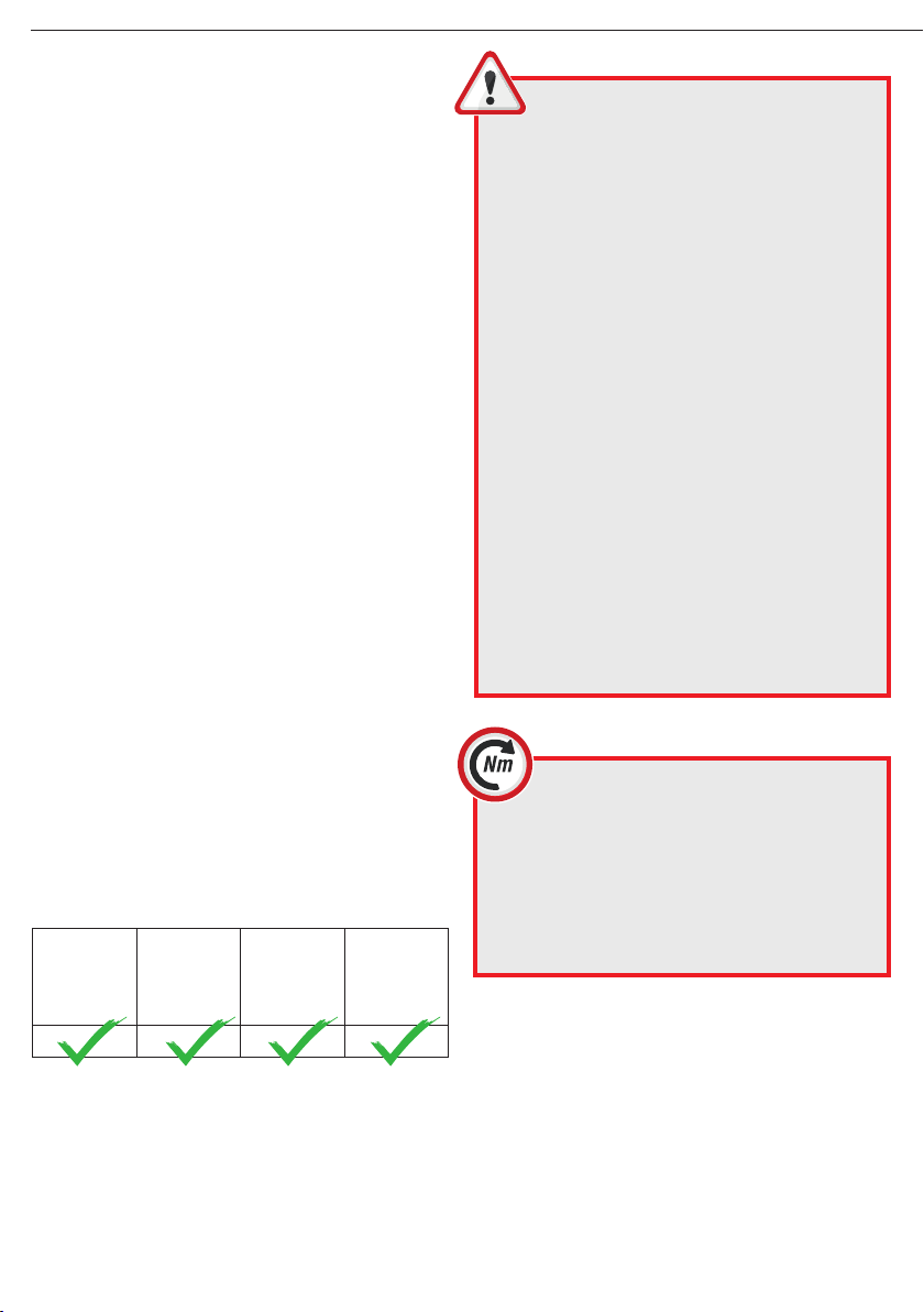
This symbol indicates an important screw
connections, and the screw must be tightened
with an specic tightening torque. The correct tigh-
tening torque is either listed on the part itself or in the-
se operating instructions. A torque wrench is required
for proper installation Screws that are not tightened
correctly, may loosen or break without warning. This
may cause a fall and lead to personal injuries and
material damage.
Installation + Operating Instructions G.2 ST / LT Seatpost

· Parallel suspension seat post
· Material: 3D forged aluminium AL-6061-T6, AL-6066-T6
· Designed for a maximum rider weight of 150 kg
· IGUS high performance polymer plain bearings/stainless steel pins
· Spring elements in 5 different strengths, selectable
according to rider weight and easily exchangeable
· Seat clamp with ne adjustment and robust grating
· For saddle rail tubes with 7mm diameter, 8 mm is optionally
available
Modell: G.2 ST
· Installation height ca. 100mm
· Spring element Länge ca. 72mm
· Suspension travel ca. 30mm
· Offset ca. 17mm
· Tube diameter ø26.4 - 34.9mm
· Lengths 350 - 450mm / kürzbar
· Weight ab ca. 600g
Modell: G.2 LT
· Installation height ca. 130mm
· Spring element Länge ca. 102mm
· Suspension travel ca. 50mm
· Offset ca. 19.5mm
· Tube diameter ø26.6 - 34.9mm
· Lengths 380 - 670mm / kürzbar
· Weight ab ca. 750g
5. FUNCTION
The parallel suspension seat post is developed to offer op-
timum riding comfort in cities as well as on rough terrain.
The suspension is progressive, i.e. the system responds
softly to small impacts and with increasing spring resist-
ance to hard impacts.
During compression the G.2 ST parallel suspension seat
post dives in up to 18 mm backwards and 22 mm down-
wards, the G.2 LT up to 33.5 mm backwards and approx.
40.5 mm downwards.
Due to the use of a highly durable at wire steel spring as
well as technical elastomers in the spring centre and on
the inside of the arms even hard impacts (e.g. deep pot-
holes) do not lead to blocking of the suspension.
Additionally the backward extension movement is damped
by the hemispherical elastomers in the head and base
part. In order to adjust the G.2 ST/ G.2 LT to the weight
of the rider and way of riding easily exchangeable spring
elements with different spring stiffness and dampers are
available.
03/12
Riding direction
Length Ø G.2 ST Seatpost
[mm] 26.4 26.6 26.8 27.2 30.6 30.9 31.6 33.9 34.9
350 x x x x x x x
400 x
450 x x x
Length Ø G.2 LT Seatpost
[mm] 26.4 26.6 26.8 27.2 30.6 30.9 31.6 33.9 34.9
380 x x x x
480 xxx
670 x
Available combinations July 2018, may change at any time
ca. 130mm
ca. 100mm
Installation + Operating Instructions G.2 ST / LT Seatpost
ca. 30mm
ca. 50mm
T25 / 12-14Nm

04/12
Exploded view G.2 ST (and G.2 LT) March 2018, may change at any time
Installation + Operating Instructions G.2 ST / LT Seatpost
6 .1
33.1
1.4 1.3 1.2 1. 1 2
7.1
3.2
3.2
2.1
7
4.2
4.3
6.2
8
5.1
5.2
1
4.1

05/12
6. COMPONENTS
SEAT CLAMP :
1. Seat clamp- assembled
1. 1 Seat clamp base with toothing
1. 2 Seat clamp pressure spring
1. 3 Seat clamp upper part
1. 4 Seat clamp screw Torx T25 with washer
(optional: Allen 5mm)
HEAD :
2. Head base part with ne toothing
2.1 Internal backstroke damper
SPRING ARM :
3. Spring arm with spring plate
3.1 Elastomer - stop damper
3.2 M5 headless screw (Allen, 2.5 mm)
SPRING ELEMENT :
4.1 Flat wire steel spring
4.2 Elastomer – central damper
4.3 Spring end cap with centring pin
SMALL PIVOT BEARING :
5.1 Igus plain bearing inner diameter 6.5 mm
5.2 Stainless steel pin outer diameter 6.5 mm
LARGE PIVOT BEARING :
6.1 Igus plain bearing inner diameter 8 mm
6.2 Stainless steel pin outer diameter 8 mm
SEATPOST BODY :
7. Seat post tube with base part
7. 1 Internal backstroke damper
8. Mudcover
7. SPRING ELEMENTS
Für die Parallelogramm gefederte G.2 ST / LT Sattelstüt-
ze werden verschieden starke Federelemente angeboten,
die einfach und schnell gewechselt werden können (siehe
Seite 08-09). Anhand der folgenden Tabelle können Sie
sich bei der Wahl des richtigen Federelements orientie-
ren, wobei die Kriterien Fahrergewicht, Fahrposition und
Fahrprol in die Entscheidung einießen.
Permissible rider weight =
body weight of the rider + additional weight (e.g. backpack)
Spring elements are available in soft, medium, standard,
hard and extra hard for riders with a body weight ranging
from 45 to 150 kg. The spring elements are marked with a
colour code indicating their properties.
Only use spring elements made by the by.schulz company
for the G series seat posts. Using third party components
may interfere with the function of the seat post and may
cause accidents, personal injuries, material damages and
the loss of claims based on liabilities and guarantees (see
page 11).
Length 72mm
Length 102mm
Installation + Operating Instructions G.2 ST / LT Seatpost
G.Serie LT Spring element
G.Serie ST Spring element

8. INSTALLATION REQUIREMENTS
· Please make sure that the inner diameter of the seat tube
of the bicycle frame and the outer diameter of the G.2 ST or
G.2 LT seat post are the same.
· Difference in dimensions can lead to the failure of the
clamping as well as accidents, personal injuries and ma-
terial damages.
· If necessary a reduction shim may be used to adjust the
diameter of the seat post to the diameter of the seat tube.
We recommend using the intended double-slotted alumi-
nium reduction shim from by .schulz with a height of 120
mm. The following diameters are available:
· When using a third party reduction shim please make sure
that it is it out of aluminium, has a minimum length of 90 mm
and is completely inserted into the seat tube.
· Always use the appropriate saddle clamps for the corres-
ponding saddle frame. Saddle clamps for saddle rails with
a diameter of 7 mm are installed by default. 8 mm saddle
clamps can also be installed. Never combine 8 mm saddle
clamps with 7 mm saddle rails or vice versa.
Note: Saddles with oval rails must not be installed.
9. INSTALLATION
9.1 Seatpost installation
Before installation:
In order to avoid scratching the seat post tube all sharp
edges and burrs at the intake part of the seat tube of the
bike frame must be removed and the area must be cle-
aned.
For metal frames we strongly recommend greasing the in-
side of the upper seat tube (when using a reduction shim
it must be greased also). This ensures problem-free sub-
sequent height adjustment of the seat post.
Do NOT use grease for frames made out of carbon bre
reinforced plastics (Carbon). Instead use a special assem-
bly paste for carbon parts and frames.
1. Please make sure that the insertion depth of the seat
post tube is not shorter than the minimum value of 90 mm.
This is illustrated by a marking on the full length seat post
tube. This marking (STOP MIN: INSERT) is located on the
back of the seat post below the extension scale. You can
nd the production serial number above the scale.
2. Particularly on small bicycle frames or frames with
pre-installed bottle cages it might be impossible to insert
the seat post tube deep enough into the seat tube of the
bicycle. In this case the seat post tube of the G.2 ST / G.2
LT can be shortened. We explicitly recommend that you
ask a specialised dealer to perform this step. After shor-
tening the seat post tube always make a new marking for
the 90 mm minimum insertion depth.
The new marking must not be made by a cut or notch
(indentation?). The seat post tube must never be shorter
than the minimum length of 90 mm.
3. After insertion into the seat tube of the bicycle the seat
post is fastened by correctly tightening the clamping screw
or closing the quick release lever of the clamping sleeve of
the seat tube (please refer to the recommendations from
the bicycle manufacturer).
Ø 34,9 > 31,6
Ø 33,9 > 31,6
Ø 33,9 > 30,9
Ø 31,6 > 27,2
Ø 30,9 > 27,2
Ø 30,2 > 27,2
Ø 30,0 > 27,2
06/12
120mm
Minimum-insert Serial No.
Installation + Operating Instructions G.2 ST / LT Seatpost

9.2 Saddle installation
1. Loosen the screws of the seat clamps on both sides (Fig.
9.2.1) until the gap of the fastening groove is approximately 8
mm. (Fig. 9.2.2). When loosening the seat clamping screws
the hidden springs inside will push the seat clamps open wi-
thout twisting.
2. Insert the seat frame from above into one of the fas-
tening grooves of the seat clamp (Fig. 9.2.3).
3. Then push the seat frame into the groove of the oppo-
site seat clamp (Fig 9.2.4). You must overcome a slight
pressure point until the seat frame audibly engages.
4. Fasten the two seat clamping screws so that the seat
frame cannot be pulled out but adjusted horizontally in the
groove.
9.3 Seat Angle / Seating Position Adjustments
1. The seat clamps and the head part of the G.2 ST / G.2
LT seat post are equipped with a forged ne toothing. This
allows you to individually adjust the seat’s angle to the
desired inclination. You can also adjust the seat frame in
the seat clamp horizontally (Fig. 9.2.5).
2. After nding your seat position tighten the two seat
clamp crews with the required torque of 12-14 Nm using a
torque wrench. The correct torque is also printed on top of
the two seat clamps.
3. To adjust the seating height open the clamping screw or
the quick release lever of the clamping sleeve of the seat
tube. Move the seat into the desired position and tighten
the screw with the specied torque or close the quick re-
lease lever.
4. When adjusting the correct seat position you should
take into account the basic damping of the seat post when
sitting on the seat. In order to compensate for the com-
pression of the spring mechanism by the weight of the
rider the seat should be set approx. 1 cm higher.Your spe-
cialist dealer will gladly advise you.
9.4 Saddle Removal
1. In order to remove the saddle rst loosen the two seat
clamp screws. The clamping mechanism opens automati-
cally because of the tension of the hidden spring inside
the seat clamp.
2. When the opening width of the fastening groove is
approx. 8 mm pull the seat upwards and out of the sadd-
le clamp. You may have to overcome a slight a pressure
point.
Mounting example
07/12
Fig.9.2.1 Fig.9.2.2
Fig.9.2.5
Fig.9.2.3 Fig.9.2.4
The M6 Seat
clamp screw Torx
T25 with washer
(optional: Allen 5mm)
have to be tightened
with 12-14 Nm.
Fig.9.2.6
Note : make sure the saddle is rmly attached to
the seat clamps.A loose saddle can lead to accidents,
personal injuries or material damage.
Installation + Operating Instructions G.2 ST / LT Seatpost
Riding direction

10. CHANGING THE SPRING ELEMENT
10.1 Removal of the Spring Element
1. Open the M5 headless screw of the large pivot bearing
in the rear arm of the G.2 ST/ G.2 LT seat post with a 2.5
mm Allen wrench. Turn the screw counter-clockwise until
it protrudes approx. 2 mm from the arm. Then push the 8
mm stainless steel pin out of the bearing.
2. Open the parallel suspension mechanism by pulling the
rear spring arm upwards by hand. The entire upper part of
the seat post will tilt forward towards the riding direction.
3. Lift up the rear spring arm in the small pivot bearing until
the spring element detaches from the spring plate.
The spring element can now be removed by hand.
The 8 mm pin has holes into which suitable tools can be
inserted to ensure that the pin and the bearing bushings
are not damaged during removal or installation.
These tools (e.g. mandrel) should be used to push the pin
out of the bearing.
08/12
Note : we recommend keeping the G.2 ST/ G.2 LT
seat post mounted in the bicycle frame when changing
the spring element.The saddle does not have to be removed
either.
Note : Use the changing the spring for a visual inspecti-
on of the elastomer damping elements in the seat post
base, the spring arms and the head of the G.2 ST/ G.2 LT
seat post. The spring mechanism must be opened comple-
tely in order to check the backstroke damper. Clean the inner
area of the head and body if necessary.
Fig. 10.1.1
Steel pin
headless screw
Fig. 10.1. 2
Fig. 10.1.3
Installation + Operating Instructions G.2 ST / LT Seatpost

10.2 Installation of the spring element
1. Place the selected original G.2 ST/ G.2 LT spring ele-
ment into the parallel suspension mechanism of the seat
post by hand. Push the spring element with the centring
pin of the spring end cap into the corresponding hole of
the spring arm plate of the front spring arm.
2. Now push the rear spring arm back downwards to ad-
just the spring element between the arms. The centring
pin of the second spring end cap must engage audibly
into the hole of the spring arm plate of the rear spring arm.
3. Fold the entire parallel suspension mechanism in the
small pivot bearing back downwards to the stop. Then
reinsert the 8 mm pin. Make sure the pin is correctly
aligned with all holes. The M5 screw must have suffi-
cient blue thread locking adhesive, apply new adhesive if
necessary. Refasten the M5 headless screw and tighten it
with a torque of 3 Nm. The pin is now safely fastened by
its centring groove.
Please check the correct t of all components before the
rst ride with the new spring.
09/12
Note : The M5 headless screw must be inserted
with medium strength thread locking adhesive
and under no circumstances may it become loose on
its own after tightening. Check if the headless screw is
still tightened with a torque of 3 Nm after approx. 1-2
hours of operation. Use a torque wrench with a 2.5
mm Allen head attached.
Fig. 10.2.2
Fig.10.2.1
centring pin
Fig. 10.2.3
Installation + Operating Instructions G.2 ST / LT Seatpost

11. MAINTENANCE / CARE
The G.2 ST/ G.2 LT seat post is based on a well thought
out concept and consists of high-quality components. With
regular maintenances this will guarantee a long riding plea-
sure.
After the rst 3 months or riding 250 km all screws must
be checked if the tightening torque is still correct. Then let
a specialist dealer perform and document this inspection
once per year or at least every 1500 km.
The mounted neoprene mud cover effectively protects the
components from dirt (mud, sand etc.) and ensures little
cleaning and low maintenance care.
Keep the parallel suspension mechanism of your G.2 ST/
G.2 LT seat post and the bearings free from dirt and mud
and clean them regularly. Stubborn dirt can normally be re-
moved with warm water and commercial detergents. Do not
use a steam jet or aggressive cleaners such as acetone,
trichloroethylene or methylene because these cleaners at-
tack components, elastomers and bearings.
Look out for cracks , deformation or other changes to the
components when cleaning the G.2 ST/ G.2 LT seat post.
Your specialist dealer will gladly help you if you have any
questions regarding the operating safety.
010/12 www.byschulz.com

NOTES :
11/12
Installation + Operating Instructions G.2 ST / LT Seatpost

www.byschulz.com
M-G2-20180726-EN
by.schulz GmbH
Vorstadtstraße 53
66117 Saarbrücken
Tel : +49(0)681-59 59 81 18
Fax : +49(0)681- 59 59 81 19
info@byschulz.com
www.byschulz.com
by.schulz © 2018
No reprints, translations or copies of any kind allowed without the prior written approval of by.schulz GmbH. Subject to technical alterations, errors
and misprints excepted. Used photos can varying from the original product
www.byschulz.com
www.youtube.com
Operating instructions
available for downloald:
Installation videos
available under :
Other manuals for G.2 ST
1
This manual suits for next models
1
Table of contents
Other by.schulz Bicycle Accessories manuals

by.schulz
by.schulz Stem Alpha 35 SDS Installation instructions

by.schulz
by.schulz D.2 ST-Ri User manual

by.schulz
by.schulz e-Bikelifter BM-60 User manual

by.schulz
by.schulz M.1 User manual

by.schulz
by.schulz Speedlifter 640119 User manual

by.schulz
by.schulz Stem Alpha +10 SDS Installation instructions

by.schulz
by.schulz D.2 ST-Ro User manual

by.schulz
by.schulz G.2 ST User manual

by.schulz
by.schulz 650123 User manual

by.schulz
by.schulz D.1 Ri User manual