4. TOOLS
which are needed for the installation:
· Torx T25 wrench
· Torque wrench with T25 Torx bit
5. INSTALLATION REQUIREMENTS
· A-Head fork shaft 1 1/8“ threadless, outer diameter 28,6 mm.
· Freely available fork shaft protrusion must be 38-39 mm.
· Spacers/risers can be installed to achieve the correct
projection.
· The threadless fork shaft can be shortened to the cor-
rect length. When cutting, make sure that the fork shaft end
still has an outer diameter of 28.6 mm and has no sharp
edges.
· An A-head claw (starnut) with an M6 thread or a similar
device must be placed in the fork shaft approx. 10 mm be-
low the end of the tube. This is used to adjust the headset
clearance.
· The brake and shift cables, as well as electrical cable
connections to the handlebars, must be of sufficient length
to keep them free of bends and to ensure that they do not
interfere with the steering in any way.
· Handlebar and stem must be compatible with each other
and must have the same clamping diameter of 31.8 mm.
We recommend the use of by,schulz handlebars, as they
are adapted for mounting on the Stem Alpha +10 ° SDS.
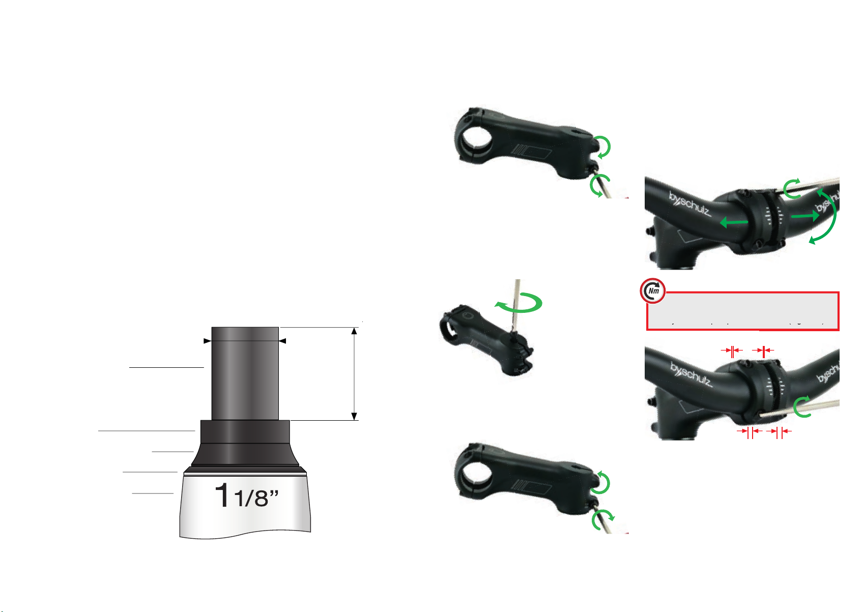
5. Then rst tighten the two upper clamping
screws without a gap and then the two lower ones
evenly with a torque spanner to 5-6 Nm (Fig. 6.2.2).
6. INSTALLATION
Before mounting, make sure that all clamping surfac-
es of the stem, fork shaft and handlebars are clean and
free of grease!
6.1 Mounting the stem
1. Loosen the two M5 Torx T25 clamping screws of the
Stem Alpha +10° SDS. (Fig. 6.1.1)
Fig. 6.1.1
2. Push the Stem Alpha +10° SDS onto the end of the fork
shaft so that it rests directly on the headset or spacer ring
(riser)
3. Insert the A-Head screw through the integrated A-Head
cap into the A-Head claw in the fork shaft and tighten light-
ly. (Fig. 6.1.2)
Fig. 6.1.2
4. Align the stem exactly
in the riding direction
5. Adjust the headset by
tightening the A-head
screw clockwise so that
there is no play. It must still
be possible to turn the fork
easily in the head tube. If
the bearing play cannot be
adjusted with the A-head
bolt, check the fork shaft
protrusion. (Fig. 6.1.2)
7. Tighten the two M5
Torx T25 clamping screws of the stem clockwise with a
torque wrench to 7-8 Nm. (Fig. 6.1.3)
Fig. 6.1.3
6. The stem is now rmly xed on the fork shaft. Check
bearing clearance and alignment of the stem, correct if
necessary. Now the handlebar assembly takes place.
6.2 Installing the handlebar
1. Loosen the four M5 Torx T25 clamping screws of the
Stem Alpha +10° SDS. (Fig. 6.1.1)
2. Place the clamping area of the handlebar on the clamp-
ing area of the stem eye.
3. Reattach the SDS front cap using all 4 screws.
4. Tighten the top two bolts slightly clockwise so that the
handlebar can be aligned and rotated to the desired grip
position. (Fig.6.2.1)
Fig. 6.2.1
evenly with a torque spanner to 5-6 Nm (Fig. 6.2.2).
Fig. 6.2.2
7. If necessary, the grips, brake and shift levers must be
realigned.
8. The Stem Alpha +10° SDS is now ready for use.
7. MAINTENANCE
After the rst assembly of the stem and a short running-in
period of approx. 20 km, check the fork and handlebar
play. Readjust them if necessary. Clean the stem regular-
ly. At every annual bicycle inspection (at least every 1000
km), the play of the headset and Stem Alpha +10° SDS
should be checked professionally.
Technical Installation Requirements
Stem Alpha +10°
Ø 28,6 mm
Protruding 1 1/8ʻʻ
A-Head fork shaft
Spacer ring
Conical spacer / Riser
Headset
Head tube/ Frame
38-39 mm
Head tube


