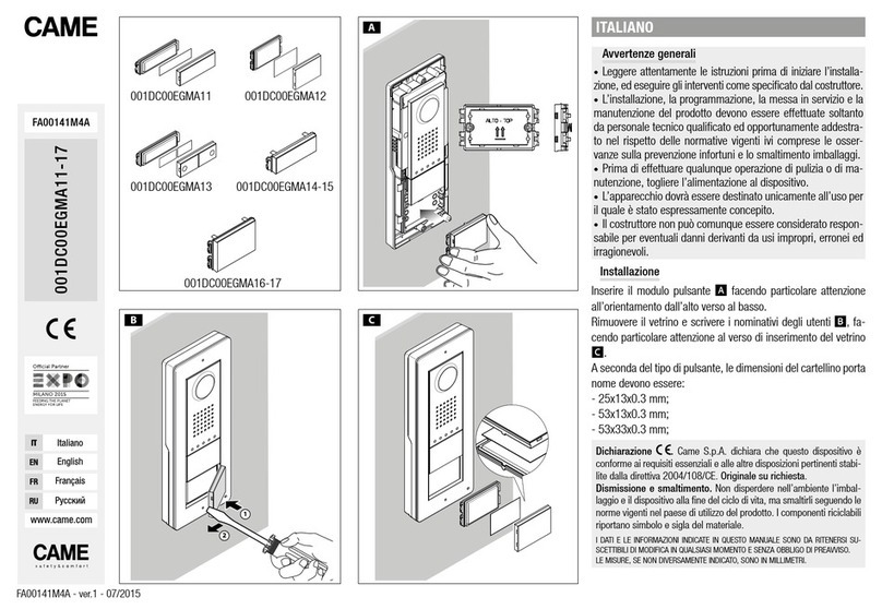
CAME LHS A/01 Manual

LHS A/01 LHS V/01
LHS V/01 PLUS
INSTALLATION AND CONFIGURATION MANUAL
FA0 16 39 - E N
EN English

Page 2- Manual FA01639-EN - 12/2021 - © CAME S.p.A. - The contents of this manual may be changed at any time and without notice. - Translation of the original instructions
GENERAL PRECAUTIONS
Read the instructions carefully before beginning the
installation and carry out the procedures as specified by the
manufacturer. • Installation, programming, commissioning
and maintenance must only be carried out by qualified,
expert technicians and in full compliance with the applicable
law. • Before carrying out any cleaning or maintenance,
disconnect the device from the power supply. • Wear anti-
static clothing and footwear if performing work on the circuit
board. • Only use this product for its intended purpose. Any
other use is hazardous. • Came S.p.A. is not liable for any
damage caused by improper, erroneous or unreasonable
use. • The product, in its original packaging supplied by
the manufacturer must only be transported in a closed
environment (railway carriage, containers, closed vehicles).
• If the product malfunctions, stop using it and contact an
authorised support centre.
If the production batch is not immediately
identifiable, please contact customer services.
The general conditions of sale are given in the
ocial CAME price lists.
Legislative References
This product complies with the applicable standards in force
at the time of manufacturing.
CAME S.p.A. declares that the product described in this
manual complies with Directive 2014/53/EU and the Radio
Equipment Regulations 2017.
The full EC declaration of conformity and UK Conformity
Assessed (UKCA) marking information can be found at www.
came.com.
98°
72°
1150
726
500
1550 ÷ 1650
Page 3- Manual FA01639-EN - 12/2021 - © CAME S.p.A. - The contents of this manual may be changed at any time and without notice. - Translation of the original instructions
PRODUCT DATA AND INFORMATION
Description
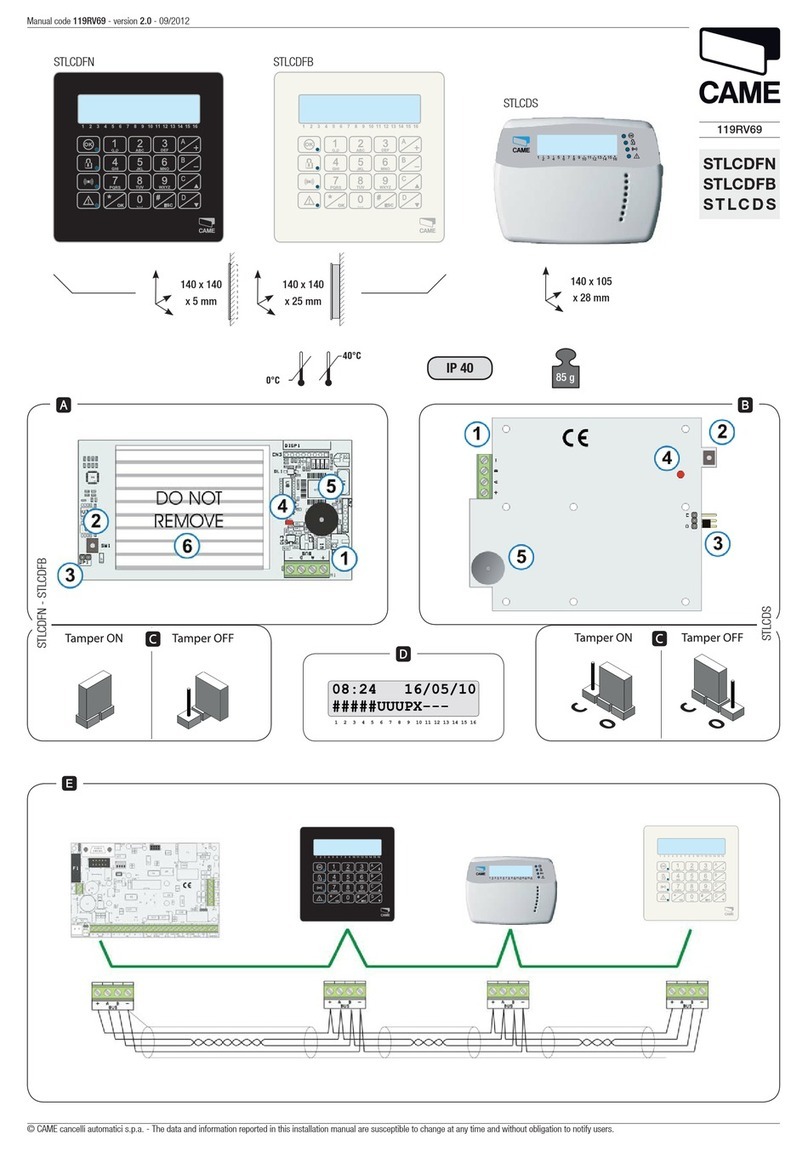
LHS A/01 (840AA-0060)
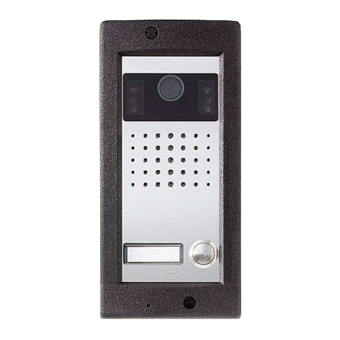
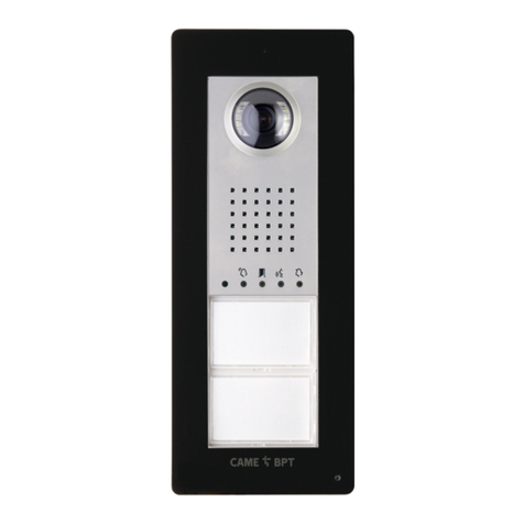
Monolith intercom entry panel for X1 system expandable up to 4 calls.
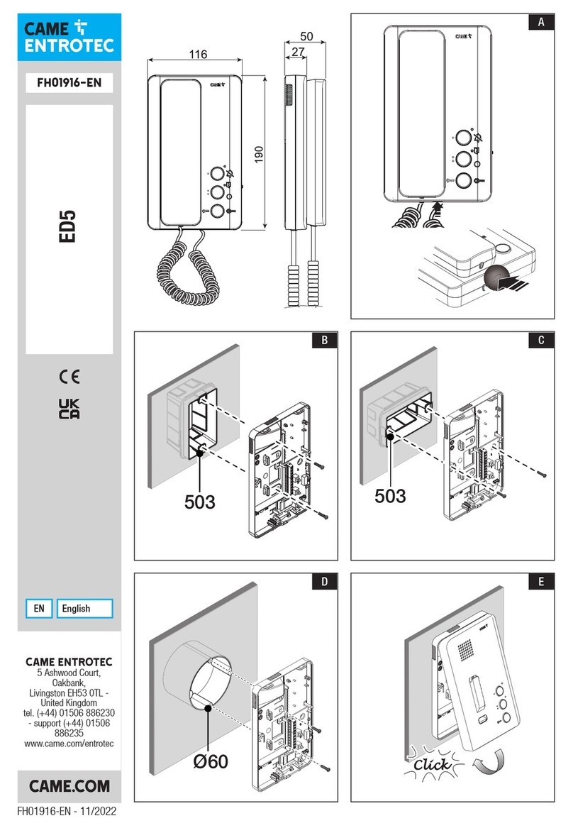
LHS V/01 (840AA-0040)
Monolith video entry panel for X1 system expandable up to 4 calls.
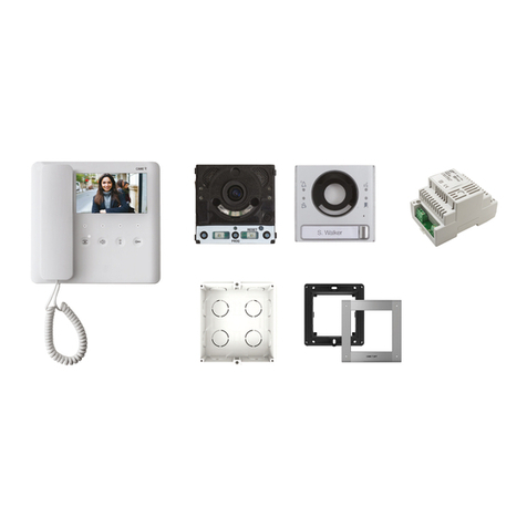
LHS V/01 PLUS (840AA-0050)
Monolith video entry panel for X1 system expandable up to 4 calls, with Bluetooth and built-in RFID reader for access control.
Description of parts
1Video camera lens*
2Front cover
3Button
4Hole cover
5Microphone
6Front cover fastening screw
7Back
8Wiring hole
9Screws and expansion plugs
Optional accessories
10 Rain cover
11 Recessed-mount profile and frame
12 Back box
13 Single button
14 Double button
* Video versions only (840AA-0050/840AA-0040)

Page 4- Manual FA01639-EN - 12/2021 - © CAME S.p.A. - The contents of this manual may be changed at any time and without notice. - Translation of the original instructions
1Speaker volume control
2Microphone volume control
3Electric lock opening time control
4RESET button
5Call button P1
6Call button P3
7Warning LED Call in progress
8Warning LED Electric lock activation
9Warning LED Conversation in progress
10 Warning LED System busy
11 Terminal block
12 PROG button
13 PROG LED (yellow)
14 Call button P2
15 Call button P4
16 CAME KEY connector and rubber cap
RESET button
The [RESET] button allows you to restart the device.

Page 5- Manual FA01639-EN - 12/2021 - © CAME S.p.A. - The contents of this manual may be changed at any time and without notice. - Translation of the original instructions
Size
135
243
11
97 23
205
170
82
34

Page 6- Manual FA01639-EN - 12/2021 - © CAME S.p.A. - The contents of this manual may be changed at any time and without notice. - Translation of the original instructions
Technical data
MODELS LHS V/01 LHS V/01 PLUS LHS A/01
IP protection rating 54 54 54
IK protection rating 09 09 09
Operating temperature (°C) -25 ÷ +55 -25 ÷ +55 -25 ÷ +55
Storage temperature (°C) * -25 ÷ +70 -25 ÷ +70 -25 ÷ +70
Dimensions (mm) 97 x 205 x 23 97 x 205 x 23 97 x 205 x 23
Consumption (mA) 190 220 150
Consumption in stand-by mode (mA) 90 110 80
Power supply (V DC) 16-18 DC 16-18 DC 16-18 DC
Video standard PAL PAL -
Minimum lighting (LUX) 11-
Standard wireless - Bluetooth LE 5.0 -
Bluetooth radio frequency (MHz) - 2400 -
RFID frequency (kHz) - 125 -
Bluetooth transmission power (dBm) - -25 ÷ +3 -
Material colour Matt grey 9023 Matt grey 9023 Matt grey 9023
(*) Before installing the product, keep it at room temperature where it has previously been stored or transported at a very high or very
low temperature.

Page 7- Manual FA01639-EN - 12/2021 - © CAME S.p.A. - The contents of this manual may be changed at any time and without notice. - Translation of the original instructions
INSTALLATION
Preliminary operations
Wall-mounted installation
Installation with rain cover (optional)

Page 8- Manual FA01639-EN - 12/2021 - © CAME S.p.A. - The contents of this manual may be changed at any time and without notice. - Translation of the original instructions
Recess installation
Button assembly

Page 9- Manual FA01639-EN - 12/2021 - © CAME S.p.A. - The contents of this manual may be changed at any time and without notice. - Translation of the original instructions

Page 10 - Manual FA01639-EN - 12/2021 - © CAME S.p.A. - The contents of this manual may be changed at any time and without notice. - Translation of the original instructions
Function of terminals
①Local power supply input 16-18 V DC
②BUS output
③Max. 12V - 1A electric lock
④Earth
⑤Door release button (NO)
⑥Programmable I/O (Default NO port contact input)
⑦Max. auxiliary contact 1 A 30 V (Default AUX 2)

Page 11 - Manual FA01639-EN - 12/2021 - © CAME S.p.A. - The contents of this manual may be changed at any time and without notice. - Translation of the original instructions
ELECTRICAL CONNECTIONS
LHS
B OUT
C
NO
+
−
+
−
−
AGT V
M1
AL
B
–
+
AL
B
+
M1
–
+
−
VAS/101
VLS/2
A
M2
B
CL RES
M/S
CL RES
M/S
1.2 1.1
AGT V
27
CONTROL BOARD 27
27 >
>
C1
NO
NC
RL1
RL2
1
C2
NO
NC

Page 12 - Manual FA01639-EN - 12/2021 - © CAME S.p.A. - The contents of this manual may be changed at any time and without notice. - Translation of the original instructions
EXAMPLE SET-UPS
Example set-up without VA/01
XDV/304
Lb
La
Lc
VAS/101
LHS
Cable length
Section Cable type
La, Lb VCM/1D or UTP CAT5
Lc 2x1mm² or 2x2.5mm²
Section Max. section length (m)
La + Lb 100 VCM/1D or 60 UTP/CAT 5
Lc 25 (2x1mm²) or 60 (2x2.5mm²)
Maximum number of internal receivers per cable type
VCM/1D
Master 321
Slave 037
UTP CAT5
Master 1
Slave 7

Page 13 - Manual FA01639-EN - 12/2021 - © CAME S.p.A. - The contents of this manual may be changed at any time and without notice. - Translation of the original instructions
Example set-up with VA/01
XDV/304
L1 L2 L3
VA/01
Lb
La
LHS LHS LHS
Cable length
Section Cable type
La, Lb VCM/1D or UTP CAT5
L1, L2, L3 VCM/2D
Section Max. section length (m)
La + Lb 100 VCM/1D or 60 UTP/
CAT 5
L1 + L2 + L3 300
La + Lb + L1 (L2, L3) 150
La + Lb + L1 + L2 + L3 600
Maximum number of internal receivers per cable type
VCM/1D
Master 4321
Slave 4567
UTP CAT5
Master 321
Slave 067

Page 14 - Manual FA01639-EN - 12/2021 - © CAME S.p.A. - The contents of this manual may be changed at any time and without notice. - Translation of the original instructions
PROGRAMMING
With a CAME KEY device, the CONNECT SetUp app can also be used for programming.
PROGRAMMING ENTRY PANELS WITHOUT VA/01 - A/01
Summary table PROG button functions
Press for 3 to 6 seconds Enter first programming
Program calls in an already programmed system
Force switch from programming calls to programming buttons
Press for 8 to 11 seconds Associating INTERCOM buttons
Press for more than 20 seconds Enabling/Disabling the intercom function
Press once Send the device serial number to programming tool
Exit programming mode
PROG LED button
Fixed Program call buttons
Slow flash Programming calls
Associating internal receivers
Program proximity cards or tags*
Quick flash Enable/disable intercom function
Associating INTERCOM buttons
*LHS PLUS only

Page 15 - Manual FA01639-EN - 12/2021 - © CAME S.p.A. - The contents of this manual may be changed at any time and without notice. - Translation of the original instructions
Entering programming mode
> 3’’
< 6’’
Press the [PROG] button for 3 seconds to enter programming mode.
Release the button within 6 seconds.
The warning LEDs will flash together with the button LEDs.
The [PROG] LED will remain on.
If the [PROG] LED does not light up, there has been a malfunction. Check the connections and try again.
Programming the call buttons
Press [P1] to configure 2 x two-way buttons (max 4 calls).
Press [P2] to configure two single buttons (max 2 calls).
The LED and the call button LEDs switch o.
Once [Call button programming] is complete, you are automatically taken to [Programming calls].
Programming calls
In [Programming calls] the LED and the [PROG] LED will flash.
The call button LEDs will remain on.
From here you can continue with further programming.
When reprogramming a system, you start from this step. You do not need to program the call buttons again.
To repeat [Programming call buttons] see the paragraph on [Reprogramming a system].

Page 16 - Manual FA01639-EN - 12/2021 - © CAME S.p.A. - The contents of this manual may be changed at any time and without notice. - Translation of the original instructions
Associating internal receivers
In [Programming calls] lift the internal-receiver handset to be configured (if present) and press and hold the and
buttons together
The video and the LED crown on the video camera will activate (video versions only).
On the entry panel, press the call button to be associated with the internal receiver.
A tone confirms that the setting has been stored.
Programming OPEN GATE and GATE STATUS function (latch)*
*Only for internal receivers with OPEN GATE function
Use this function to control and display the gate status (open/closed). The operator status is indicated by the LED on the
internal receiver switching on or o.
The operator can be controlled via the entry panel auxiliary relay.
The DOOR STATUS function is active by default. It is automatically deactivated when the OPEN GATE and GATE
STATUS function is enabled.

Page 17 - Manual FA01639-EN - 12/2021 - © CAME S.p.A. - The contents of this manual may be changed at any time and without notice. - Translation of the original instructions
Enable the function when associating the internal receiver.
Press and hold the button. The LED switches on to confirm the
function was activated.
Repeat the procedure for each internal receiver on which you
wish to activate the function.
Re-associating the internal receiver automatically deactivates
the OPEN GATE function, which must be reactivated.
Programming the AUTOMATIC DOOR RELEASE function*
*For internal receivers with AUTOMATIC DOOR RELEASE function only
This function is used to open the entrance automatically when there is a call from the entry panel. No communication is
activated and the call ends automatically.
Enabling the function allows the user to activate/deactivate it as required. The function is enabled by default.
> 5s
Program the function when associating the internal receiver.
Press and hold the button for more than 5 seconds to enable or
disable the function.
If the LED remains on, the function is enabled.
If the LED flashes, the function is disabled.
End the call and repeat programming for all of the other internal receivers.

Page 18 - Manual FA01639-EN - 12/2021 - © CAME S.p.A. - The contents of this manual may be changed at any time and without notice. - Translation of the original instructions
Programming proximity cards or tags*
*LHS V/01 PLUS model only
This function is used to program proximity cards or tags, and assign one or more outputs to each to be controlled.
Do this when there are no internal receivers being associated.
Each new programmed card/tag overwrites the previous one.
①In [Programming calls], run the proximity card or tag over the RFID reader.
②Assign a function to the card/tag by pressing and holding the corresponding call button. Continue to press the button until
you hear a tone to confirm.
Key Output/Function
P1 Door release
P2 Auxiliary relay
P3 Relay 1 of actuator (e.g. VSL/2)
P4 Relay 2 of actuator (e.g. VSL/2)
Saved cards and tags can be deleted by restoring the device to factory settings. See the paragraph [Restoring
factory settings].

Page 19 - Manual FA01639-EN - 12/2021 - © CAME S.p.A. - The contents of this manual may be changed at any time and without notice. - Translation of the original instructions
Programming the intercom function
Enabling/Disabling the intercom function
With VSE/301.01, please see the power supply unit documentation. Leave the function disabled on the entry
panel.
The feature is disabled by default.
+ 20’’
Press and hold the [PROG] button for approximately 20 seconds, until the and LEDs flash quickly for 3 seconds. The
[PROG] LED will flash quickly.
A beep confirms set-up was successful and the [PROG] LED switches o.
In case of activation the LED will switch o, and the LED will stay on for a further 2 seconds.
In case of deactivation the LED will switch o, and the LED will stay on for a further 2 seconds.
Associating INTERCOM buttons
Do this only after associating a call button to every receiver.
< 8’’
> 11’’
Press the [PROG] button for at least 8 seconds.
Release the [PROG] button within 11 seconds.
The [PROG] LED and the and warning LEDs flash quickly.

Page 20 - Manual FA01639-EN - 12/2021 - © CAME S.p.A. - The contents of this manual may be changed at any time and without notice. - Translation of the original instructions
On the internal receiver, press the INTERCOM button with which you wish
to associate it.
Wait for the beep that will confirm successful programming.
Repeat for all the internal receivers you wish to include in the
intercommunicating group.
Exiting programming mode
To exit programming mode, press the [PROG] button. All LEDs except the button LEDs will switch o.
Reprogramming a system
In an already programmed system, pressing the [PROG] button takes you directly to the [Programming calls] phase.
You do not need to perform [Programming call buttons] again.
To force [Programming call buttons] again, press and hold the [PROG] button for at least 3 seconds and no
longer than 6.
You will need to run [Associate internal receivers] and [Program OPEN GATE and GATE STATUS function] again
This manual suits for next models
2
Table of contents
Other CAME Intercom System manuals

CAME
CAME AGT A200K User manual

CAME
CAME 001DC02ENIGMA User manual

CAME
CAME AGTMTMVKIT User manual

CAME
CAME AGT V EVO User manual

CAME
CAME XTS 5IP WH User manual

CAME
CAME XTS 7IP WH WIFI User manual

CAME
CAME PLACO-VC User manual

CAME
CAME VK01 User manual

CAME
CAME PLX A User manual

CAME
CAME FUTURAKITVC04 User manual

CAME
CAME 001CS1PLCO User manual

CAME
CAME Bpt TARGHA GSM VR1 User manual

CAME
CAME 001DC00EGMA11 User manual

CAME
CAME XTS 7IP WH WIFI User manual

CAME
CAME AGT V Specification sheet

CAME
CAME BPT DVC/01 Owner's manual

CAME
CAME AGT A200 User manual

CAME
CAME BPT THANGRAM Owner's manual

CAME
CAME XVP S Instruction sheet

CAME
CAME 001DC01EARY User manual