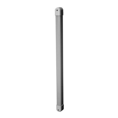
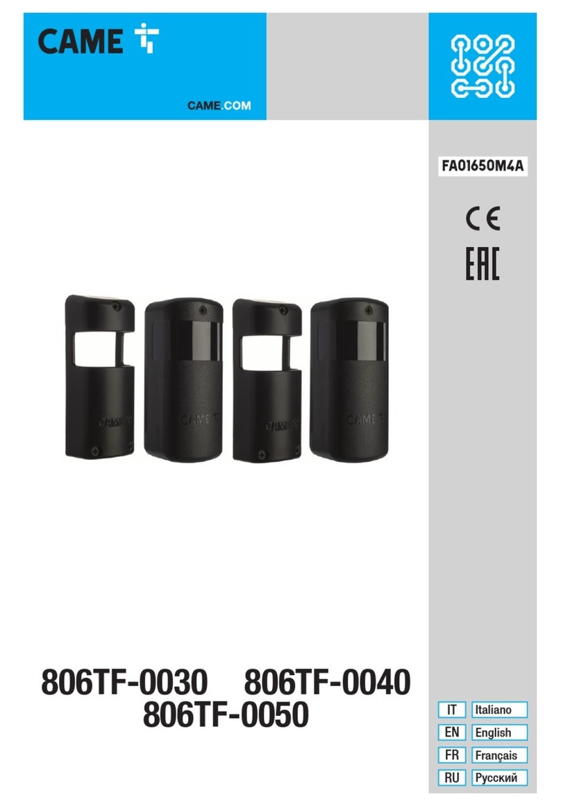
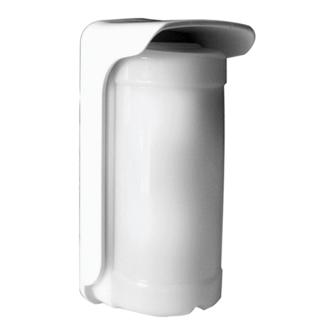
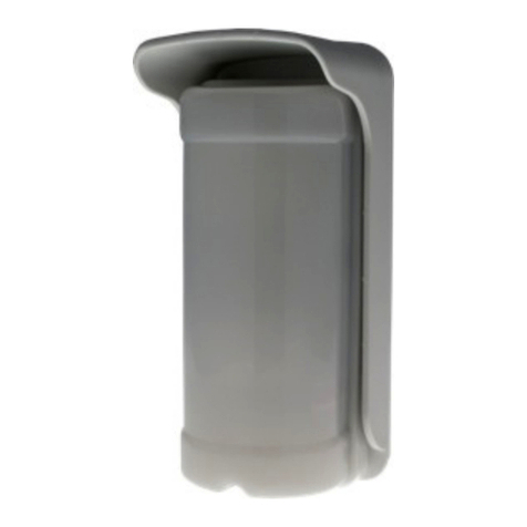
CAME MR8534 User manual

MR8534/MR8570/MR8590
1
2
3
4
5
6
7
8
9
10
11
E
R
L
A
U
B
T
Z
E
R
T
I
F
I
Z
I
E
R
U
N
G
N
A
C
H
DIN 18650
E
N
A
B
L
E
S
A
C
C
O
R
D
A
N
C
E
W
I
T
H
SPECIFICHE TECNICHE
DESCRIZIONE
ITALIANO
1. profilato
2. clip di supporto
3. connettore
4. DIP-switch
5. vite di calibrazione
6. ricevitore
7. tappi laterali
8. clip con vite di regolazione dell’ angolo
9. emettitore (TX)
10. pulsante
11. frontalino
infrarosso attivo con soppressone dello sfondo
400 mm (L) x 70 mm (P) (4 punti a 2 m di altezza di montaggio)
1,3 m a 3,5 m
64 ms (typ)
1 minuto
12 V - 24 V AC +/-10% ; 12 V - 30 V DC -5%/+10%
(da far funzionare solo con unità di alimentazione compatibili con le normative SELV)
95 mA @ 24 V AC/ 70 mA @ 24 V DC; 170 mA @ 12 V AC/ 130 mA @ 12 V DC (MASTER)
85 mA @ 24 V AC/ 60 mA @ 24 V DC; 180 mA @ 12 V AC/ 113 mA @ 12 V DC (altri moduli)
2 relé (liberi di potenziale)
42 V AC/DC
1 A (resistente)
30 W (DC) / 42 VA (AC)
1 optoaccoppiatore (libero di potenziale)
30 V
stato alto: >10 V DC; stato basso: <1 V DC
4 (fino a 6 se 24 V DC)
min. 5% a una lunghezza di onde IR di 850 mm
IP54
-25° a +55° C; 0-95% umidità relativa, non condensante
20 anni
DIN 18650-1: ch. 5.7.4; EN 16005 ch. 4.6.8;
EN 12978; IEC/EN 61508 (SIL2)
EN ISO 13849-1 Performance Level «c» CAT. 2
(a condizione che il sistema di controllo effettui il monitoraggio del rilevatore almeno una volta per ogni ciclo porta)
Tecnologia :
Campo di emissione:
Altezza di montaggio:
Tempo di risposta:
Tempo massima di prensenza:
Alimentazione:
Consumo di corrente massima:
Uscite:
Tensione massima ai contatti:
Corrente massima ai contatti:
Capacitá in non alimentazione:
Ingressi:
Tensione massima ai contatti:
Soglia di:
Numero massimo di moduli:
Riflessività:
Grado di protezione:
Gamma di temperatura:
Durata di vita stimata:
Certificazione:
Le specifiche tecniche possono essere modificate senza preavviso.
Misurato in condizioni ottimali.
CONSERVARE PER USO FUTURO
PREVISTO PER STAMPA A COLORI
RILEVATORE DI SICUREZZA
PER PORTE GIREVOLI
Per i prodotti a partire dalla versione 0500
Vedere l’etichetta delprodotto per ilnumero diserie
E' un rilevatore di sicurezza per porte automatiche girevoli basato sulla tecnologia ad infrarossi attivi. Per proteggere l’area
di fronte all’anta mobile, è necessario installare i moduli nella parte superiore e da entrambi i lati della porta.
MR8534-70-90/FA01345M06 - 06/2019

1
2
3
2 cm
12-24 V
AC-DC
COM
NC
NO
COM
NO
NC
NO NC
*
*
180°
MONTAGGIO DEL PROFILATO
POSIZIONAMENTO DEI MODULI
CABLAGGIO
VERDE
MARRONE
GIALLO
BIANCO
NERO
ROSA
GRIGIO
VIOLA
ROSSO**
BLU**
ALIMENTAZIONE
SEGNALE D’ARRESTO
Lato di apertura
della porta
SEGNALE D’APERTURA
Lato di chiusura
della porta
MONITORAGGIO***
NESSUNA ALIMENTAZIONE
NESSUN RILEVAMENTO
RILEVAMENTO
Il modulo connesso all’ operatore diventa il
MASTER.
Montare il profilato vicino al bordo di chiusura della porta.
Lasciare 2 cm per inserire i tappi neri. Tenere conto della posizione
futura dei clip bianchi e dei fori e fissativi.
Collegare i moduli
inserendo il CAVO
SLAVE in uno dei 2
spazi previsti.
* Stato uscita quando il rilevatore è operativo
** Ai fini della conformità con la EN 16005 e la DIN 18650,
è richiesta una connessione all’uscita di prova dell’operatore.
*** Se l’operatore non é auto sorvegliato, collegare il BLU su 0 V ed il ROSSO su +12 V – 30 V DC.
Utilizzare un cacciavite per svitare
i moduli.
L’emettitore TX deve essere posizionato
vicino ai bordi della porta da proteggere.
Il clip munito di vite deve essere vicino
all’emettitore!
Se necessario, girare il modulo e riposizionare i
clip come indicato.
1. Togliere i clip
2. Ruotare i clip di 180°
3. Rifissare i clip
MR8534-70-90/FA01345M06 - 06/2019

4
6
5
4
5
X
REGOLAZIONE
VERIFICA DELLA SICUREZZA DELLA PORTA
CALIBRAZIONE
IMPORTANTE: Testare il corretto
funzionamento dell’installazione
prima di partire.
Se necessario, avvicinare o
allontanare la porta e lanciare una
calibrazione.
Dopo aver modificato un tasto il LED arancione lampeggia.
Confermare le regolazioni di tutti i moduli mantenendo premuto il
pulsante del MASTER.
Il numero di lampeggiamenti verdi (x) indica i moduli collegati.
Premere brevemente il pulsante del MASTER per lanciare la
calibrazione di tutti i moduli.
Uscire dal campo di rilevazione!
IL LED SI SPEGNE > LA ZONA DI RILEVAZIONE È OK!
La zona di rilevazione è troppo piccola:
girare la vite in senso orario.
La zona di rilevazione è troppo grande:
girare la vite in senso antiorario.
Uscire dal campo di rilevazione.
Se necessario, cambiare l’angolo o disattivare il sfondo (DIP 3 = OFF).
Lanciare una calibrazione.
La velocità di lampeggiamento
aumenta a mano a mano che vi
avvicinate alla posizione ottimale.
LATO DI
MONTAGGIO FREQUENZA SFONDO ZONA
NON COPERTA
RELÉ 1
ARRESTO
RELÉ 2
APERTURA
FREQ A
FREQ B
ON
OFF
ALTA*
BASSA
ON
OFF
LED durante rilevazione:
R1 > ROSSO
R2 > VERDE
Scegliere frequenze
diverse per i moduli
vicini.
Riflettività dello
sfondo insufficiente:
selezionare OFF
Valori approssimativi
per un altezza di 2 m:
alta= 40 cm, bassa= 15 cm
ROSSO-
VERDE
SPENTO
VERDE
ROSSO
ARANCIONE
ARANCIONE SPENTOVERDE
VALORI DI FABBRICA
* Raccomandata per la maggior parte delle applicazioni.
Altezza di montaggio > 2,7 m: selezionate BASSA per essere
conformi alla EN 16005 e la DIN 18650.
MR8534-70-90/FA01345M06 - 06/2019

2
1
4
5
1
1
3
1
1
2
1
2
1
2
1
1
1
2
1
2
3
1
2
4
3
2
MR8534-70-90 / FA01345M06--Traduzione delle istruzioni originali -- 4SAFE / 42.7707 / V5 – 06.19
SEGNALI LED
Il LED arancione
lampeggia 1 volta
ogni 3 secondi.
Il LED arancione
rimane acceso in
permanenza.
Il LED arancione
lampeggia
velocemente.
Lanciare una calibrazione.
Rispedirci il rilevatore indietro per verifica tecnica.
Mantenere il pulsante premuto per confermare
la regolazione del tasto DIP.
Interrompere e ripristinare l’alimentazione.
Se il LED arancione lampeggia ancora, sostituire il
rilevatore.
Il rilevatore non
reagisce ma si
puó lanciare una
calibrazione.
Verificare i cavi.
- CollegaRe il ROSSO ed il BLU all’uscita monitorata.
- Se l’operatore non ha monitoring:
CollegaRe il BLU su 0V e il ROSSO su +12 V - 30 V DC.
Il LED arancione
lampeggia 2 volte
ogni 3 secondi.
Il LED arancione
lampeggia 3 volte
ogni 3 secondi.
Il LED arancione
lampeggia 4 volte
ogni 3 secondi.
Il LED arancione
lampeggia 5 volte
ogni 3 secondi.
Verificare i cavi tra i moduli.
Lanciare un conteggio dei moduli:
Mantenere premuto il pulsante del MASTER.
L’alimentazione è troppo
bassa o troppo alta.
Verificare l’alimentazione.
Riducere la lunghezza del cavo o cambiare il cavo.
Il LED rosso o verde si
accende ogni tanto
o resta acceso in
permanenza.
Il rilevatore segnala un
problema interno.
Regolazione errata della
zona di non rilevazione.
La sorveglianza é attivata,
ma l’entrata di sorveglianza
non é alimentata.
Errore di comunicazione
tra i moduli.
Il rilevatore ha un problema
di memoria.
Regolazione DIP-switch in
attesa di conferma.
Il rilevatore riceve poca
energia dall’infrarosso.
Calibrazione errata
Il rilevatore è disturbato
(lampade o altro rilevatore). Selezionare una frequenza diversa per ogni modulo (DIP 2).
Lanciare una calibrazione.
Errore di calibrazione. Verificare l’altezza di montaggio.
Cambiare la posizione della vite di calibrazione.
Lanciare una calibrazione.
Disattivare lo sfondo (DIP 3 = OFF).
Verificare se il DIP 4 é in posizione corretta.
Lanciare una calibrazione.
• L’impiego del prodotto in situazioni diverse non é autorizzato e non puó essere garantito dal costruttore.
• È responsabilità del produttore effettuare una valutazione dei rischi ed installare il rilevatore e il sistema porte in conformità con
i regolamenti nazionali e internazionali e con gli standard di sicurezza applicabili.
• Il fabbricante non puó essere ritenuto responsabile di un’installazione scorretta e di regolazioni inappropriate del rilevatore.
• Il sensore deve essere installato solo da personale professionalmente qualificato.
• Riparazioni o tentativi di riparazione effettuati da personale non autorizzato invalideranno la garanzia.
Came S.p.A.- Via Martiri Della Liberta 15 - IT-31030 DOSSON DI CASIER (TV)
TEL (+39) 0422 4940 - FAX (+39) 0422 4941 - [email protected] - www.came.com
CAME dichiara che MR8534 / MR8570 / MR8590 è conforme alle direttive europee 2014/30 / UE
(EMC), 2006/42/CE e 2011/65/UE (RoHS).
Questo prodotto deve essere smaltito separatamente dai rifiuti urbani non differenziati.
Originale su richiesta.
PRODOTTO COMMERCIALIZZATO
Lanciare una calibrazione e uscire dal campo di
rilevazione.
Cambiare l’angolo degli spot.
Disattivare lo sfondo (DIP 3 = OFF).

1
2
3
4
5
6
7
8
9
10
11
E
R
L
A
U
B
T
Z
E
R
T
I
F
I
Z
I
E
R
U
N
G
N
A
C
H
DIN 18650
E
N
A
B
L
E
S
A
C
C
O
R
D
A
N
C
E
W
I
T
H
TECHNICAL SPECIFICATIONS
1. profile
2. supporting clip
3. main connector
4. DIP-switch
5. calibration screw
6. receiver
ENGLISH
7. end cap
8. clip with angle adjustment screw
9. transmitter (TX)
10. push button
11. front face
active infrared with background suppression
400 mm (W) x 70 mm (D) (at 2 m mounting height; 4 spots active)
1.3 m to 3.5 m
64 ms (typ)
1 minute
12 V - 24 V AC +/-10% ; 12 V - 30 V DC -5%/+10%
(to be operated from SELV compatible power supplies only)
95 mA @ 24 V AC/ 70 mA @ 24 V DC; 170 mA @ 12 V AC/ 130 mA @ 12 V DC (MASTER)
85 mA @ 24 V AC/ 60 mA @ 24 V DC; 180 mA @ 12 V AC/ 113 mA @ 12 V DC (other modules)
2 relays (free of potential contact)
42 V AC/DC
1 A (resistive)
30 W (DC) / 42 VA (AC)
1 optocoupler (free of potential contact)
30 V
high: >10 V DC; low: <1 V DC
4 (up to 6 if 24 V DC)
min. 5% at IR-wavelength of 850 nm
IP54
-25 °C to +55 °C; 0-95% relative humidity, non condensing
20 years
DIN 18650-1: ch. 5.7.4; EN 16005 ch. 4.6.8;
EN 12978; IEC/EN 61508 (SIL2)
EN ISO 13849-1 Performance Level «c» CAT. 2
(under the condition that the door control system monitors the sensor at least once per door cycle)
Technology:
Emission field:
Mounting height:
Reaction time:
Max. presence time:
Supply voltage:
Max current consumption:
Output:
Max. contact voltage
Max. contact current
Max. switching power
Input:
Max. contact voltage:
Voltage threshold:
Max. number of modules:
Reflectivity:
Degree of protection:
Temperature range:
Expected lifetime:
Conformity:
PLEASE KEEP FOR FURTHER USE
DESIGNED FOR COLOUR PRINTING
Specifications are subject to changes without prior notice.
All values measured in specific conditions.
SAFETY SENSOR
FOR AUTOMATIC REVOLVING DOORS
User’s Guide for product version 0500 andhigher
See product label for serial number
Is a safety sensor for automatic revolving doors based on active infrared technology. It secures the area in front of the
moving door leaf. To do so, modules must be installed on the top rail of the door leaf.
DESCRIPTION
MR8534/MR8570/MR8590
MR8534-70-90/FA01345M06 - 06/2019

1
2
3
2 cm
12-24 V
AC-DC
COM
NC
NO
COM
NO
NC
NO NC
MR8534-70-90/FA01345M06 - 06/2019
*
*
180°
MOUNTING THE PROFILE
POSITIONING THE MODULES
WIRING
GREEN
BROWN
YELLOW
WHITE
BLACK
PINK
GREY
VIOLET
RED**
BLUE**
POWER SUPPLY
STOP IMPULSE
Opening side of door
REOPENING IMPULSE
Closing side of door
TEST OUTPUT***
NO POWER
NO DETECTION
DETECTION
The module connected to the door controller
becomes the MASTER.
Plug the SLAVE
CABLE between
the modules in
one of the two
placements.
Mount the profiles as close as possible to the closing edge. Leave 2 cm
for the black end caps. Take the position of the white clips into account
before drilling and fastening the screws.
* Output status when sensor is operational
** For compliance with EN 16005 and DIN 18650, connection to door controller test output is required.
*** If door controller is not tested: conncect BLUE to 0 V and RED to +12 V - 30 V DC.
To loosen the modules, please use
a screwdriver.
Place the transmitter (TX) next to the door
edges that needs to be protected.
Position the angle adjustment clip next to the
transmitter.
If necessary, turn the module and
reposition the clips as indicated.
1. Detach the clips
2. Turn them by 180°
3. Reattach

4
6
5
4
5
X
SETTINGS
DOOR SAFETY CHECK
CALIBRATION
IMPORTANT: Test the good
functioning of the installation
before leaving the premises.
If necessary, position spots
closer to or away from the door
and relaunch a calibration.
After changing a DIP-switch, the orange LED flashes.
A LONG push on the push button of the MASTER
confirms the settings of ALL MODULES.
Afterwards, a number of green flashes (x) indicates
the number of connected modules.
A SHORT push on the button of the MASTER launches a
calibration on ALL MODULES.
Do not stand in the detection field!
When the LED is off on all modules, the detection zone is OK.
The detection zone is too short:
turn the screw clockwise.
The detection zone is too long:
turn the screw anticlockwise.
Step out of the detection field.
If necessary, change angle or switch off background (DIP 3 = OFF).
Launch a new calibration.
The flashing speed of
the LED increases when
approaching the optimal
position.
MOUNTING
SIDE FREQUENCY BACKGROUND UNCOVERED
ZONE
RELAY 1
STOP
RELAY 2
REOPENING
FREQ A
FREQ B
ON
OFF
HIGH*
LOW
ON
OFF
LED during detection:
R1 > RED
R2 > GREEN
Set different
frequencies on
modules close to
each other.
Not enough background
reflectivity: switch to OFF Approximate values at 2 m:
high= 40 cm, low = 15 cm
RED-GREEN OFF
GREEN
RED
ORANGE
ORANGE GREEN OFF
FACTORY VALUE
* Recommended for most applications.
Mounting height > 2.7 m: set to LOW for
EN 16005 and DIN 18650-conformity.
MR8534-70-90/FA01345M06 - 06/2019

2
1
4
5
1
1
3
1
1
2
1
2
1
2
1
1
1
2
1
2
3
1
2
4
3
2
MR8534-70-90 / FA01345M06—Original instructions--4SAFE / 42.8280 / V5 – 06.19
LED-SIGNALS
The ORANGE LED
flashes 1 x
every 3 seconds.
Bad calibration
The ORANGE LED is
on permanently.
The ORANGE LED
flashes quickly.
The RED or GREEN
LED is ON sporadicly
or permanently.
Launch a calibration.
Send the sensor back for a technical check-up.
Corfirm the DIP-switch setting:
long push on the push button.
Cut and restore power supply.
If orange LED flashes again, replace sensor.
The sensor does not
react, but a calibration
can be launched.
Chech wiring.
- Door control with test:
Connect RED and BLUE wires to test output.
- Door control without test:
Connect BLUE to 0 V and RED to +12 V - 30 V DC.
The ORANGE LED
flashes 2 x
every 3 seconds.
The ORANGE LED
flashes 3 x
every 3 seconds.
The ORANGE LED
flashes 4 x
every 3 seconds.
The ORANGE LED
flashes 5 x
every 3 seconds.
Check power supply (tension, capacity).
Reduce the cable length or change cable.
Check wiring between modules.
Launch a module count: long push on push button
of MASTER.
Power supply is out of limit.
The sensor signals an
internal fault.
Bad adjustment of the
uncovered zone.
The monitoring is activated,
but the test input is not
powered.
Communication error
between modules.
The sensor receives
not enough IR-energy.
The sensor encounters a
memory problem.
DIP-switch setting
awaiting confirmation.
The sensor is disturbed by
lamps or another sensor. Select a different frequency for each module (DIP 2).
Launch a calibration.
Calibration error Check mounting height.
Change position of calibration screw.
Launch a new calibration.
Switch off background (DIP3: OFF)
Check if the DIP-switch 4 is in correct position.
Launch a calibration.
Came S.p.A.- Via Martiri Della Liberta 15 - IT-31030 DOSSON DI CASIER (TV)
TEL (+39) 0422 4940 - FAX (+39) 0422 4941 - info@came.com - www.came.com
CAME hereby declares that MR8534/MR8570/MR8590 is in compliance with European
directives 2014/30/EU (EMC), 2006/42/EC (Machinery) and 2011/65/EU (RoHS).
Original upon request.
This product should be disposed of separately from unsorted municipal waste.
BUY-TO-SELL PRODUCT
- The device cannot be used for purposes other than its intended use. All other uses cannot be guaranteed by the manufacturer of the sensor.
- The manufacturer of the door system is responsible for carrying out a risk assessment and installing the sensor and the door system in compliance
with applicable national and international regulations and standards on door safety.
- The manufacturer of the sensor cannot be held responsible for incorrect installations or inappropriate adjustments of the sensor.
- Only trained and qualified personnel may install and setup the sensor.
- The warranty is invalid if unauthorized repairs are made or attempted by unauthorized personnel.
Launch a new calibration and step out of
the detection field.
Change angle of spots.
Switch off background (DIP 3: OFF).

1
2
3
4
5
6
7
8
9
10
11
E
R
L
A
U
B
T
Z
E
R
T
I
F
I
Z
I
E
R
U
N
G
N
A
C
H
DIN 18650
E
N
A
B
L
E
S
A
C
C
O
R
D
A
N
C
E
W
I
T
H
SPECIFICATIONS TECHNIQUES
DESCRIPTION
FRANCAIS
infrarouge actif avec suppression de l’arrière-plan
400 mm (L) x 70 mm (P) (4 spots à 2 m de hauteur de montage)
1,3 m à 3,5 m
64 ms (typ)
1 minute
12 V - 24 V AC +/-10% ; 12 V - 30 V DC -5%/+10%
(l’appareil doit uniquement fonctionner sur basse tension de protection (SELV) avec coupure électrique sûre)
95 mA @ 24 V AC/ 70 mA @ 24 V DC; 170 mA @ 12 V AC/ 130 mA @ 12 V DC (MASTER)
85 mA @ 24 V AC/ 60 mA @ 24 V DC; 180 mA @ 12 V AC/ 113 mA @ 12 V DC (autres modules)
2 relais (libres de potentiel)
42 V AC/DC
1 A (résistif)
30 W (DC) / 42 VA (AC)
1 optocoupleur (libre de potentiel)
30 V
Etat haut: > 10 V; Etat bas: < 1 V
4 (jusque 6 si 24 V DC)
min 5% à une longueur d’ondes IR de 850 nm
IP54
-25 °C à +55 °C; 0-95% humidité relative, non condensante
20 ans
DIN 18650-1: ch. 5.7.4; EN 16005 ch. 4.6.8;
EN 12978; IEC/EN 61508 (SIL2)
EN ISO 13849-1 Performance Level «c» CAT. 2
(à condition que l’opérateur surveille le détecteur au moins une fois par cycle de porte)
Technologie :
Champ d’émission :
Hauteur de montage :
Temps de réponse :
Temps de présence max:
Alimentation :
Consommation de courant max. :
Sorties :
Tension max. aux contacts :
Courant max. aux contacts :
Pouvoir de coupure max. :
Entrée:
Tension max. aux contacts:
Seuil de tension:
Nombre max. de modules:
Réflectivité:
Degré de protection:
Gamme de température :
Durée de vie estimée :
Conformité :
1. profilé
2. clip de support
3. connecteur principal
4. DIP-switch
5. vis de calibrage
6. récepteur
7. flasque
8. clip avec vis d’ajustement angulaire
9. émetteur (TX)
10. bouton poussoir
11. face avant
Les spécifications techniques sont susceptibles de changer sans préavis.
Toutes les valeurs sont mesurées dans des conditions optimales.
A CONSERVER POUR RÉFÉRENCE ULTÉRIEURE
PRÉVU POUR IMPRESSION EN COULEUR
Manuel d’utilisation pour produits à partir de la version 0500
Voir étiquette produit pour le numéro de série
DÉTECTEUR DE SÉCURISATION
POUR PORTES TOURNANTES AUTOMATIQUES
Est un détecteur de sécurisation pour portes tournantes automatiques basé sur la technologie infrarouge actif. Il sécurise la zone située
devant le vantail mobile de la porte. Pour ce faire, les modules sont installés sur le bord supérieur du vantail de la porte.
MR8534/MR8570/MR8590
MR8534-70-90/FA01345M06 - 06/2019

1
2
3
2 cm
12-24 V
AC-DC
COM
NC
NO
COM
NO
NC
NO NC
*
*
180°
VERT
BRUN
JAUNE
BLANC
NOIR
ROSE
GRIS
VIOLET
ROUGE**
BLEU**
ALIMENTATION
SORTIE DE TEST***
MONTAGE DU PROFILÉ
POSITIONNEMENT DES MODULES
CÂBLAGE
SIGNAL D’ARRÊT
Côté d’ouverture
de la porte
SIGNAL DE
RÉ-OUVERTURE
Côté de fermeture
de la porte
PAS D’ALIMENTATION
PAS DE DÉTECTION
DÉTECTION
Le module connecté à l’opérateur devient le
MASTER.
Branchez le
CÂBLE SLAVE
entre les modules
dans un des 2
emplacements
prévus.
Montez le profilé aussi près que possible du bord de fermeture de la
porte. Laissez 2 cm pour placer les capuchons noirs. Tenez compte
de la future position des clips blancs avant de forer et de fixer les vis.
* Position des sorties quand le détecteur est opérationnel.
** Pour être conforme à la DIN 18650 et la EN 16005,
ces fils doivent être connectés à la sortie test de l’opérateur.
***Si l’opérateur n’est pas monitoré : branchez le BLEU sur 0 V et le ROUGE sur +12 V - 30 V DC
Pour défaire les modules, merci
d’utiliser un tournevis.
Placez l’émetteur (TX) près des bords de porte
à protéger.
Positionnez le clip muni d’une vis près de
l’émetteur.
Si nécessaire, tournez le module et
repositionnez les clips comme indiqué.
1. Ôtez les clips
2. Tournez les clips de 180°
3. Refixez les clips
MR8534-70-90/FA01345M06 - 06/2019

4
6
5
4
5
X
RÉGLAGES
VÉRIFICATION DE LA SÉCURISATION DE LA PORTE
CALIBRATION
IMPORTANT: Testez le bon
fonctionnement de l’installation
avant de quitter les lieux.
Si nécessaire, rapprochez ou
éloignez les spots de la porte et
lancez une nouvelle calibration.
Après avoir modifié un DIP-switch, la LED orange clignote.
Maintenez le bouton poussoir du MASTER enfoncé
pour confirmer les réglages de TOUS LES MODULES.
Le nombre de clignotements verts (x) indique le nombre de
modules interconnectés.
Enfoncez brièvement le bouton poussoir du MASTER pour
lancer un calibrage de TOUS LES MODULES.
Sortez du champ de détection!
La LED s’éteint > La zone de détection est OK.
Une zone de détection trop petite :
Tournez la vis dans le sens des aiguilles
d’une montre
Une zone de détection trop longue :
Tournez la vis dans le sens contraire
des aiguilles
Sortez du champ de détection.
Si nécessaire, changez l’angle ou désactivez l’arrière-plan (DIP 3 = OFF).
Lancez une nouvelle calibration.
La vitesse de clignotement
augmente à l’approche de la
position optimale.
CÔTÉ DE
MONTAGE FRÉQUENCE ARRIÈRE-PLAN ZONE
NON COUVERTE
RELAIS 1
ARRÊT
RELAIS 2
RÉ-OUVERTURE
FREQ A
FREQ B
ON
OFF
HAUTE*
BASSE
ON
OFF
LED pendant détection:
R1 > ROUGE
R2 > VERTE
Choisissez des
fréquences différentes
pour les modules
proches les uns des
autres.
Réflectivité de l’arrière-
plan insuffisante:
sélectionnez OFF
Valeurs approximatives pour
hauteur de 2 m: haute = 40
cm, basse = 15 cm
ROUGE-VERT ETEINT
VERT
ROUGE
ORANGE
ORANGE ETEINT
VERT
VALEURS USINE
* Recommandé pour la plupart des applications.
Hauteur de montage > 2,7 m, sélectionnez BASSE pour être
conforme à la EN 16005 et la DIN 18650.
MR8534-70-90/FA01345M06 - 06/2019

2
1
4
5
1
1
3
1
1
2
1
2
1
2
1
1
1
2
1
2
3
1
2
4
3
2
MR8534-70-90 / FA01345M06—Notice originale--4SAFE / 42.8280 / V5 – 06.19
SIGNAUX LED
La LED orange
clignote 1x toutes
les 3 secondes.
La LED orange reste
allumée en
permanence.
La LED orange
clignote vite.
La LED rouge ou
verte s’allume
sporadiquement ou
reste allumée.
Lancez une calibration.
Renvoyez le détecteur à l’usine pour vérification
technique.
Maintenez le bouton poussoir enfoncé pour
confirmer le réglage du DIP-switch.
Coupez et restaurez l’alimentation.
Si la LED orange clignote encore, changez le détecteur.
Le détecteur ne
réagit pas mais un
calibrage peut être
lancé.
Vérifiez le câblage.
- Connectez le ROUGE et le BLEU à la sortie
de test de l’opérateur.
- Si l’opérateur n’est pas monitoré : branchez le
BLEU sur 0 V et le ROUGE sur +12 V - 30 V DC.
La LED orange
clignote 2x toutes
les 3 secondes.
La LED orange
clignote 3x toutes
les 3 secondes.
La LED orange
clignote 4x toutes
les 3 secondes.
La LED orange
clignote 5x toutes
les 3 secondes.
Vérifiez l’alimentation.
Réduisez la longueur du câble ou changez le câble.
Vérifiez le câblage entre modules.
Lancez un comptage des modules :
maintenez enfoncé le bouton poussoir du MASTER.
L’alimentation est trop basse
ou trop haute.
Le détecteur signale un
problème interne.
Mauvais réglage de la zone
de non couverture.
La surveillance est activée,
mais l’entrée de surveillance
n’est pas alimentée.
Erreur de communication
entre modules.
Le détecteur rencontre
un problème de mémoire.
Réglage DIP-switch en
attente de confirmation.
Le détecteur reçoit
trop peu d’énergie IR.
Mauvaise calibration
Le détecteur est perturbé
par des lampes ou un autre
détecteur proche.
Sélectionnez une autre fréquence par module (DIP 2).
Lancez une calibration.
Erreur de calibration Vérifiez la hauteur de montage.
Changez la position de la vis de calibration.
Lancez une calibration.
Désactivez l’arrière-plan (DIP 3: OFF).
Vérifiez si le DIP 4 est reglé correctement.
Lancez une calibration.
Came S.p.A.- Via Martiri Della Liberta 15 - IT-31030 DOSSON DI CASIER (TV)
TEL (+39) 0422 4940 - FAX (+39) 0422 4941 - info@came.com - www.came.com
CAME déclare par la présente que le MR8534 / MR8570 / MR8590 est conforme aux directives
européennes 2014/30 / EU (EMC), 2006/42 / CE (Machines) et 2011/65 / EU (RoHS).
Original sur demande.
Ce produit doit être éliminé séparément des déchets municipaux non triés.
PRODUIT ACHETER POUR VENDRE
• Toute autre utilisation de l’appareil en dehors du but autorisé ne peut pas être garantie par le fabricant.
• Le fabricant du système de porte est responsable de l’évaluation des risques et de l’installation du détecteur en comformité
avec les prescriptions nationales et internationales en matière de sécurité des portes.
• Le fabricant ne peut être tenu pour responsable de l’installation incorrecte ou des réglages inappropriés du détecteur.
• Le montage et la mise en service du détecteur doivent être effectués uniquement par un spécialiste formé.
• La garantie est nulle lorsque toute réparation est effectuée sur le produit par du personnel non autorisé.
Lancez une calibration.et sortez du champ
de détection.
Changez l’angle des spots.
Désactivez l’arrière-plan (DIP 3: OFF).

1
2
3
4
5
6
7
8
9
10
11
E
R
L
A
U
B
T
Z
E
R
T
I
F
I
Z
I
E
R
U
N
G
N
A
C
H
DIN 18650
E
N
A
B
L
E
S
A
C
C
O
R
D
A
N
C
E
W
I
T
H
TECHNISCHE DATEN
BESCHREIBUNG
DEUTSCH
1. Profil
2. Haltebock
3. Anschlussstecker
4. DIP-Schalter
5. Einlernschraube
6. Empfänger
7. Seitenkappe
8. Haltebock mit Schraube zur
Winkeleinstellung
9. Sender (TX)
10. Drucktaster
11. Frontblende
Aktiv Infrarot mit Hintergrundausblendung
400 mm (B) x 70 mm (T) (4 Spots bei 2 m Montagehöhe)
1,3 m bis 3,5 m
64 ms (typ)
1 Minute
12 V - 24 V AC +/-10% ; 12 V - 30 V DC -5%/+10%
(Das Gerät darf nur an Schutzkleinspannungen (SELV) mit sicherer elektrischer Trennung betrieben werden)
95 mA @ 24 V AC/ 70 mA @ 24 V DC; 170 mA @ 12 V AC/ 130 mA @ 12 V DC (MASTER)
85 mA @ 24 V AC/ 60 mA @ 24 V DC; 180 mA @ 12 V AC/ 113 mA @ 12 V DC (andere Module)
2 Relais (Potentialfreier Kontakt)
42 V AC/DC
1 A (Ohmsche Last)
30 W (DC) / 42 VA (AC)
1 Optokoppler (Potentialfrei)
30 V
Hoch: >10 V; Tief: <1 V
4 (bis zu 6 bei 24 V DC)
min 5% bei IR-Wellenlänge von 850 nm
IP54
-25 °C bis +55 °C; 0-95% relative Luftfeuchtigkeit, nicht kondensierend
20 Jahre
DIN 18650-1: ch. 5.7.4; EN 16005 ch. 4.6.8;
EN 12978; IEC/EN 61508 (SIL2)
EN ISO 13849-1 Performance Level «c» CAT. 2
(unter der Bedingung dass der Türantrieb den Sensor mindestens einmal pro Türzyklus überwacht)
Technologie:
Emissionsfeld:
Montagehöhe:
Reaktionszeit:
Max. Anwesenheitszeit:
Stromversorgung:
Stromaufnahme:
Ausgang:
Max. Kontaktspannung:
Max. Schaltstrom:
Max. Schaltleistung:
Eingang:
Max. Kontaktspannung:
Schaltschwelle:
Max Gesamtanzahl der Module:
Benötigte Reflektivität:
Schutzklasse:
Temperaturbereich:
Geschätzte Lebensdauer:
Konformität:
Änderungen vorbehalten.
Alle Werte gemessen bei Optimalbedingungen.
ZUR SPÄTEREN VERWENDUNG AUFBEWAHREN
ZUM FARBDRUCK ENTWORFEN
ABSICHERUNGSSENSOR
FÜR AUTOMATISCHE KARUSSELLTÜREN
Bedienungsanleitung für Produktversion ab0500 Siehe Produktetikett für
Seriennummer
Ist ein Aktivinfrarotsensor zur Absicherung von automatischen Karusselltüren.
Um den Bereich vor dem drehenden Türflügel abzusichern, müssen die Module an der Türoberkante montiert werden.
MR8534/MR8570/MR8590
MR8534-70-90/FA01345M06 - 06/2019

1
2
3
2 cm
12-24 V
AC-DC
COM
NC
NO
COM
NO
NC
NO NC
*
*
180°
MONTAGE DER PROFILE
POSITIONIERUNG DER MODULE
ANSCHLUSS
GRÜN
BRAUN
GELB
WEISS
SCHWARZ
ROSA
GRAU
VIOLETT
ROT**
BLAU**
STROM-
VERSORGUNG
STOP-IMPULS
Bandseite
ÖFFNUNGS-IMPULS
Bandgegenseite
ÜBERWACHUNG***
KEIN STROM
KEINE ERFASSUNG
ERFASSUNG
Das Modul, dass an der Türsteuerung
angeschlossen wird, ist der MASTER.
Schliessen Sie
das SLAVE KABEL
zwischen den
Modulen an.
Profile so nah wie möglich an der abzusichernden Kante montieren.
2 cm Abstand für schwarze Endkappe einhalten. Bei Bohrungen für
Kabeldurchführung und Anbringen der Befestigungs-schrauben, auf
spätere Positionierung der weißen Halteböcke achten.
Der Türantrieb und das Türprofil müssen ordnungsgemäß geerdet sein.
* Stellung des Ausgangs wenn Sensor betriebsbereit.
** Gemäß EN 16005 und DIN 18650 ist Anschluss am Testausgang der Türsteuerung erforderlich.
*** Wenn Türsteuerung nicht getestet wird: BLAU an 0 V und ROT an +12 V - 30 V DC anschliessen.
Zum Lösen der Module, bitte
einen Schraubenzieher nutzen.
Die Senderlinsen (TX) an die abzusichernde
Kante positionieren.
Haltebock mit Einstellschraube muss sich
neben den Senderlinsen befinden.
Falls notwendig, das Modul drehen und die
Halteböcke wie abgebildet positionieren.
1. Abklemmen
2. Um 180° drehen
3. Festklemmen
MR8534-70-90/FA01345M06 - 06/2019

4
6
5
4
5
X
EINSTELLUNGEN
TÜRSICHERHEITSCHECK
EINLERNEN (CALIBRATION)
WICHTIG: Testen Sie ob der Sensor
ordnungsgemäß installiert ist bevor
Sie die Installation verlassen.
Falls notwendig, Spots zur Tür hin
oder von Tür weg positionieren und
Einlernprozess wiederholen.
Nach Veränderung eines DIP-Schalters, blinkt die orange LED.
Ein LANGES Drücken des Tasters auf dem MASTER,
bestätigt die Einstellungen auf ALLEN MODULEN.
Anschliessend wird durch grünes Blinken (x) die Anzahl der
angeschlossenen Module angezeigt.
Ein KURZES Drücken des Tasters auf dem MASTER, startet
einen Einlernprozess auf ALLEN MODULEN.
Bitte nicht im Erfassungsfeld stehen!
LED ist aus auf allen Modulen > Tastweite ist OK!
Tastweite ist zu kurz: Schraube im
Uhrzeigersinn drehen
Tastweite ist zu lang: Schraube im
Gegenuhrzeigersinn drehen
Aus dem Erfassungsfeld treten.
Wenn notwendig, Winkel ändern oder Hintergrund deaktivieren (DIP 3 = OFF).
Neues Einlernen starten.
Die Blinkfrequenz der LED
erhöht sich, je näher man
der Solleinstellung kommt.
MONTAGE-
SEITE FREQUENZ HINTERGRUND GRAUZONE
RELAIS 1
STOP
RELAIS 2
ÖFFNUNG
FREQ A
FREQ B
AN
AUS
HOCH*
NIEDRIG
ON
OFF
LED bei Erfassung:
R1 > ROT
R2 > GRÜN
Benachbarten Modulen
bitte unterschiedliche
Frequenzen zuweisen.
Zu wenig
Hintergrundreflektivität:
Hintergrund AUS-schalten
Geschätzte Werte für eine
Montagehöhe von 2 m:
hoch= 40 cm, niedrig = 15 cm
ROT-GRÜN AUS
GRÜN
ROT
ORANGE
ORANGE AUS
GRÜN
WERKSEINSTELLUNG
* Für die meisten Anwendungen empfohlen.
Montagehöhe > 2,7 m: auf NIEDRIG schalten für
EN 16005 und DIN 18650-Konformität
MR8534-70-90/FA01345M06 - 06/2019

2
1
4
5
1
1
3
1
1
2
1
2
1
2
1
1
1
2
1
2
3
1
2
4
3
2
MR8534-70-90 / FA01345M06 — Originalbedienungsanleitung--4SAFE / 42.8280 / V5 – 06.19
LED-SIGNALE
Orange LED blinkt
1x alle 3 Sekunden.
Die orange LED
leuchtet
ununterbrochen auf.
Orange LED blinkt
schnell.
Einlernen starten.
Den Sensor zur Überprüfung zurück ans Werk
schicken.
Lange auf Drucktaster drücken um
DIP-Einstellungen zu bestätigen.
Stromversorgung überprüfen.
Kabellänge kürzen oder Kabel austauschen.
Sensor zeigt keine
Funktion, aber
Einlernen
funktioniert.
Anschluss überprüfen.
- ROT/BLAU an Überwachungsausgang anklemmen.
- Bei Türsteuerung ohne Überwachung:
BLAU auf 0 V und ROT auf +12 V - 30 V DC.
Orange LED blinkt
2x alle 3 Sekunden.
Orange LED blinkt
3x alle 3 Sekunden.
Orange LED blinkt
4x alle 3 Sekunden.
Orange LED blinkt
5x alle 3 Sekunden.
Verkabelung zwischen Modulen überprüfen.
Modulzählung starten: Lange auf Drucktaster des
MASTERS drücken bis grüne LED Anzahl Module
anzeigt.
Spannungsversorgung zu
niedrig oder zu hoch.
Stromversorgung des Sensors aus/einschalten.
Leuchtet orange LED wieder auf, Sensor austauschen.
Der Sensor meldet einen
internen Fehler.
Schlechte Einstellung der
Grauzone.
Die Überwachung ist
aktiviert und der
Überwachungseingang
des Sensors ist stromlos.
Kommunikationsfehler
zwischen Module.
Der Sensor hat ein Speicher-
problem.
DIP-Schalter Einstellung in
Erwartung der Bestätigung.
Der Sensor empfängt zu
wenig IR-Energie.
Rote oder grüne LED
leuchtet sporadisch
oder ununterbrochen
auf.
Schlechtes Einlernen
Der Sensor wird durch
Lampen oder einen anderen
Sensor gestört.
Pro Modul verschiedene Frequenz wählen (DIP 2).
Einlernen starten.
Fehler beim Einlernen Montagehöhe überprüfen.
Position der Einlernschraube ändern.
Einlernen starten.
Hintergrund deaktivieren (DIP 3 = OFF).
Überprüfen ob DIP 4 (Grauzone) korrekt geschaltet ist.
Einlernen starten.
Came S.p.A.- Via Martiri Della Liberta 15 - IT-31030 DOSSON DI CASIER (TV)
TEL (+39) 0422 4940 - FAX (+39) 0422 4941 - info@came.com - www.came.com
Hiermit erklärt CAME, dass MR8534/MR8570/MR8590 den europäischen Richtlinien
2014/30 / EU (EMV), 2006/42 / EG (Maschinen) und 2011/65 / EU (RoHS) entspricht.
Original auf Anfrage erhältlich.
Dieses Produkt ist getrennt vom unsortierten Hausmüll zu entsorgen
ERTRIEBENES FREMDERZEUGNIS
• Andere Anwendungen des Geräts entsprechen nicht dem zugelassenen Zweck und können nicht vom Hersteller garantiert werden.
• Die Risikobeurteilung und die Installation des Sensors und des Türsystems gemäß der nationalen und internationalen Vorschriften und
Normen zur Türsicherheit, fällt in den Verantwortungsbereich des Türherstellers.
• Der Hersteller kann die Verantwortung für mangelhafte Installationen oder Einstellungen des Sensors nicht übernehmen.
• Montage und Inbetriebnahme des Sensors nur durch geschultes Fachpersonal.
• Jeglicher Reparaturversuch durch unbefugtes Personal annulliert die werksseitige Garantie.
Einlernen starten.und aus dem
Erfassungsfeld treten.
Winkel ändern.
Hintergrund deaktivieren (DIP 3 = OFF).

1
2
3
4
5
6
7
8
9
10
11
E
R
L
A
U
B
T
Z
E
R
T
I
F
I
Z
I
E
R
U
N
G
N
A
C
H
DIN 18650
E
N
A
B
L
E
S
A
C
C
O
R
D
A
N
C
E
W
I
T
H
ESPECIFICACIONES TÉCNICAS
DESCRIPCIÓN
ESPANOL
1. perfil
2. clip de soporto
3. conector principal
4. DIP-switch
5. tornillo de calibración
6. receptor
7. tapas laterales
8. clip con tornillo de la regulación del ángulo
9. transmisor (TX)
10. pulsador
11. cara frontal
Infrarrojo activo con supresión del segundo plano.
400 mm (L) x 70 mm (P) (4 spots a 2 m de la altura de instalación).
1,3 m a 3,5 m
64 ms (typ)
1 minuto
12 V- 24 V AC +/-10% ; 12 V- 30 V DC -5%/+10%
(para accionamiento exclusivo desde fuentes de alimentación compatibles con SELV)
95 mA @ 24 V AC/ 70 mA @ 24 V DC; 170 mA @ 12 V AC/ 130 mA @ 12 V DC (MASTER)
85 mA @ 24 V AC/ 60 mA @ 24 V DC; 180 mA @ 12 V AC/ 113 mA @ 12 V DC (otros módulos)
42 V AC/DC
1 A (resistivo)
30 W (DC) / 42 VA (AC)
1 optoacoplador (sin potencia)
30 V
Estado alto: > 10 V; Estado bajo: < 1 V
4 (hasta 6 si 24 V DC)
mín. 5% a una longitud de ondas IR de 850 nm
IP54
-25°C a +55°C; 0-95% humedad relativa, no condensador
20 años
DIN 18650-1: ch. 5.7.4; EN 16005 ch. 4.6.8;
EN 12978; IEC/EN 61508 (SIL2)
EN ISO 13849-1 Performance Level «c» CAT. 2
(con la condición de que el sistema de control de puertas supervise el sensor una vez como mínimo por ciclo de puerta)
Tecnología:
Zona de emisión:
Altura de instalación:
Tiempo de respuesta:
Tiempo máx. de presencia:
Alimentación:
Consumo corriente máx.:
Salidas:
Tensión máx. en contactos:
Corriente máx. en contactos:
Nivel de corte máx.:
Entrada:
Tensión máx. en contactos:
Umbral de tensión:
Numero máx. de módulos:
Reflectividad:
Nivel de protección:
Gama de temperatura:
Vida útil estimada:
Certificación:
Las especificaciones técnicas pueden modificarse sin previo aviso.
Medido en las condiciones óptimas.
GUARDAR PARA USOS FUTUROS
PREVISTA PARA LA IMPRESIÓN EN COLOR
DETECTOR DE SEGURIDAD
PARA PUERTAS AUTOMÁTICAS GIRATORIAS
Para los productos a partir de la versión 0500
Consulte laetiqueta del producto para el número deserie.
Es un detector de seguridad para puertas automáticas giratorias basado en la tecnología infrarrojo activo que pro-tege el área
frente a la hoja móvil de la puerta. Para hacer eso, los módulos se instalan en la parte superior de la hoja de la puerta.
MR8534/MR8570/MR8590
MR8534-70-90/FA01345M06 - 06/2019

1
2
3
2 cm
12-24 V
AC-DC
COM
NC
NO
COM
NO
NC
NO NC
*
*
180°
INSTALACIÓN DEL PERFIL
COLOCACIÓN DE LOS MÓDULOS
CONEXIÓN
VERDE
MARRON
AMARILLO
BLANCO
NEGRO
ROSA
GRIS
MORADO
ROJO**
AZUL**
ALIMENTACIÓN
SEÑAL DE PARADA
Lado de apertura
de la puerta
SEÑAL DE APERTURA
Lado de cierre
de la puerta
CONTROL***
SIN ALIMENTACIÓN
SIN DETECCIÓN
DETECCIÓN
El módulo conectado al operador se convierte
en el MASTER.
Coloque el perfil lo más cerca posible del borde de cierre de la puerta.
Deje 2 cm para colocar las tapas negras. Tenga en cuenta la posición
futura de los clips blancos antes de perforar y de fijar los tornillos.
Conecte el CABLE
SLAVE entre los
módulos en uno
de los 2 sitios
previstos.
* Estado de la salida con el sensor en funcionamiento
** Para cumplir la EN 16005 y la DIN 18650 se requiere una conexión a la salida
de prueba del controlador de puerta.
*** Si el operador no es auto vigilado, conecte el AZUL sobre 0V y el ROJO sobre +12V -30V DC.
Para ajustar los módulos, use el
destornillador.
El transmisor TX (véase pegatina) debe
colocarse cerca de los perfiles laterales de
puerta que deben protegerse.
El clip con tornillo debe situarse cerca del
transmisor.
1. Quite los clips
2. Gire los clips 180°
3. Vuelva a fijar los clips
En caso de necesidad, girar el módulo y
recolocar los clips como indicado.
MR8534-70-90/FA01345M06 - 06/2019

4
6
5
4
5
X
AJUSTES
COMPROBACIÓN DE LA SEGURIDAD DE LA PUERTA
CALIBRACIÓN
IMPORTANTE: Comprobar el buen
funcionamento de la instalación
antes de irse del lugar.
Si es necesario acerque o aleje los
haces de la puerta y lance una
calibración.
Cuando se modifica un DIP-switch, el LED naranja parpadea.
Confirme los ajustes de todos los módulos manteniendo pulsado el
botón de arranque del MASTER.
El número de parpadeos verdes (x) indica el número de módulos
conectados.
Pulse brevemente el botón de arranque del MASTER para lanzar
una calibración de todos los módulos.
Salga del campo de detección!
EL LED SE APAGA > LA ZONA DE DETECCIÓN ES CORRECTA!
La zona de detección es demasiado pequeña:
Gire el tornillo en el sentido
de las agujas del reloj.
La zona de detección es demasiado larga:
Gire el tornillo en el sentido contrario
de las agujas del reloj.
Salga del campo de detección.
Si es necesario, cambie el ángulo o desactiva el segundo plano (DIP 3 = OFF).
Lance una calibración.
La velocidad del parpadeo
aumenta a medida que se
acerca a la posición óptima.
LADO DE LA
INSTALACIÓN FRECUENCIA SEGUNDO
PLANO ZONA NO
CUBIERTA
RELÉ 1
PARADA
RELÉ 2
APERTURA
FREC A
FREC B
ON
OFF
ALTA*
BAJA
ON
OFF
LED durante detección:
R1 > ROJO
R2 > VERDE
Seleccione frecuencias
diferentes para los
módulos que están
cerca unos de otros.
Reflectividad del
entorno insuficiente:
seleccione OFF
Valores aproximativos
para una altura de 2 m:
alta= 40 cm, baja= 15 cm
ROJO-VERDE OFF
VERDE
ROJO
NARANJA
NARANJA OFF
VERDE
VALORES DE FÁBRICA
*Recomendado para la mayoría de las aplicaciones.
Altura de instalación > 2,7 m, seleccione BAJA para
conformidad con EN 16005 y DIN 18650
MR8534-70-90/FA01345M06 - 06/2019

2
1
4
5
1
1
3
1
1
2
1
2
1
2
1
1
1
2
1
2
3
1
2
4
3
2
MR8534-70-90 / FA01345M06 -- Traducción de las instrucciones originales -- 4SAFE / 42.8284 / V5 – 06.19
SEÑAL DEL LED
El LED naranja
parpadea 1 vez
cada 3 segundos.
El LED naranja se
queda encendido.
El LED naranja
parpadea
rápidamente.
Lance una calibración.
Devuelva el detector para verificación técnica.
Mantenga el botón de arranque presionado
para confirmar el ajuste del DIP-switch.
Conecte y desconecte la alimentación.
Si el LED naranja sigue parpadeando, cambie el
detector.
El detector no
reacciona pero se
puede lanzar una
calibración.
Compruebe el cableado.
- Conecte el ROJO y el AZUL a la salida controlada.
- Si el operador no está controlado:
conecte el AZUL a 0 V y el ROJO a +12 V - 30 V DC.
El LED naranja
parpadea 2 veces
cada 3 segundos.
El LED naranja
parpadea 3 veces
cada 3 segundos.
El LED naranja
parpadea 4 veces
cada 3 segundos.
El LED naranja
parpadea 5 veces
cada 3 segundos.
Compruebe los cables entre los módulos.
Lance un recuento de los módulos: mantenga
presionado el botón de arranque del MASTER.
La alimentación es
demasiado baja o
demasiado elevada.
Compruebe la alimentación.
Reduzca la longitud del cable o cambie el cable.
El LED rojo o verde se
enciende
esporádicamente o
permanece encendido. Ajuste errado de la zona de
no detección.
Calibración errada
El detector está perturbado
por lámparas o por otro
detector.
Seleccione una frec. diferente para cada módulo (DIP 2).
Lance una calibración.
Error de calibración Compruebe la altura de montaje.
Cambie la posición del tornillo de la calibración.
Lance una calibración.
Desactive el segundo plano (DIP 3 = OFF).
El detector señala un
problema interno.
Se activa la supervisión pero
la entrada de supervisión no
está alimentada.
Error de comunicación
entre los módulos.
Problema con la memoria
del detector.
El detector no recibe la
energía suficiente.
Ajuste DIP-switch en
espera de confirmación.
Compruebe la zona de no detección (DIP 4).
Lance una calibración.
Came S.p.A.- Via Martiri Della Liberta 15 - IT-31030 DOSSON DI CASIER (TV)
TEL (+39) 0422 4940 - FAX (+39) 0422 4941 - info@came.com - www.came.com
Por la presente CAME declara que MR8534 / MR8570 / MR8590 cumple con las directivas
europeas 2014/30 / EU (EMC), 2006/42 / EC (Maquinaria) y 2011/65 / EU (RoHS).
Original a pedido.
Este producto debe eliminarse por separado de los residuos municipales sin clasificar.
PRODUCTO DE COMPRA PARA VENDER
• Cualquier otro uso del dispositivo que no se contempla en la finalidad prevista, quedará excluido de la garantía del fabricante.
•El fabricante del sistema de puertas será responsable de realizar una evaluación de riesgos y de instalar el sensor, así como de
asegurarse de que el sistema de puertas cumple los estándares y normativas nacionales e internacionales sobre seguridad de puertas.
• El fabricante declina toda responsabilidad por instalaciones o ajustes incorrectos del sensor.
• El detector lo instalará y configurará exclusivamente personal debidamente formado y cualificado.
• La garantía será anulada si se realizan reparaciones no autorizadas por personal no autorizado.
Lance una calibración y salga del campo de
detección.
Cambie el ángulo de los haces.
Desactive el segundo plano (DIP 3 = OFF).
Other manuals for MR8534
1
This manual suits for next models
5
Table of contents
Languages:
Other CAME Security Sensor manuals