FA01281M4A - 02/2019
ENGLISH
Warning
– Carefully read the instruction manual before installation and any intervention specified by the manufacturer. –
Installation, programming and maintenance must be carried out by qualified personnel in compliance with current
legislatives. – In the event of intervention on the electronic circuit board, wear anti-static clothing and appropriate
footwear. – The product must be used for the purpose for which it has been designed other uses are considered
dangerous. – The manufacturer will not be held responsible for damage of or incorrect use. – Check all warnings
specified in the installation manual and product use. – In order to avoid accidental contact with any live parts, place
the cover on the product after connection. – During installation do not allow people, including children to approach
the automation and the manoeuvre area. – Do not use this product in the event of bad weather conditions. – The
manufacturer CAME SPA, declares that the product described in this manual complies with 2014/53/UE Directive.
- The complete text of the EU conformity declaration is available on: www.came.com.
DISMANTLE AND WASTE DISPOSAL – Packaging components (carton, plastic etc.) can be disposed of as solid
urban waste. The product components (metal, electronic circuit board, batteries etc.) must be waste separated.
Waste collection methods must be checked with existing rules present in the area of installation.
DO NOT REALEASE INTO THE ENVIRONMENT
Manual contents may be modified at any time without having to respect any notice period.
Dimensions, unless specified, are in mm
The pictures in the manual are purely illustrative.
Description
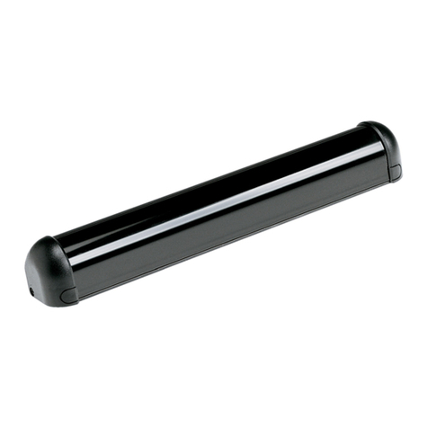
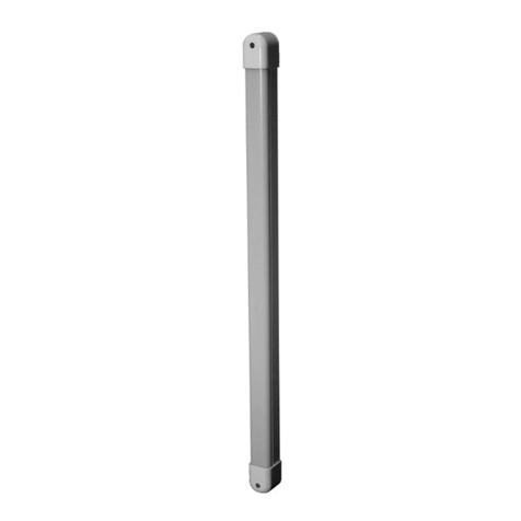
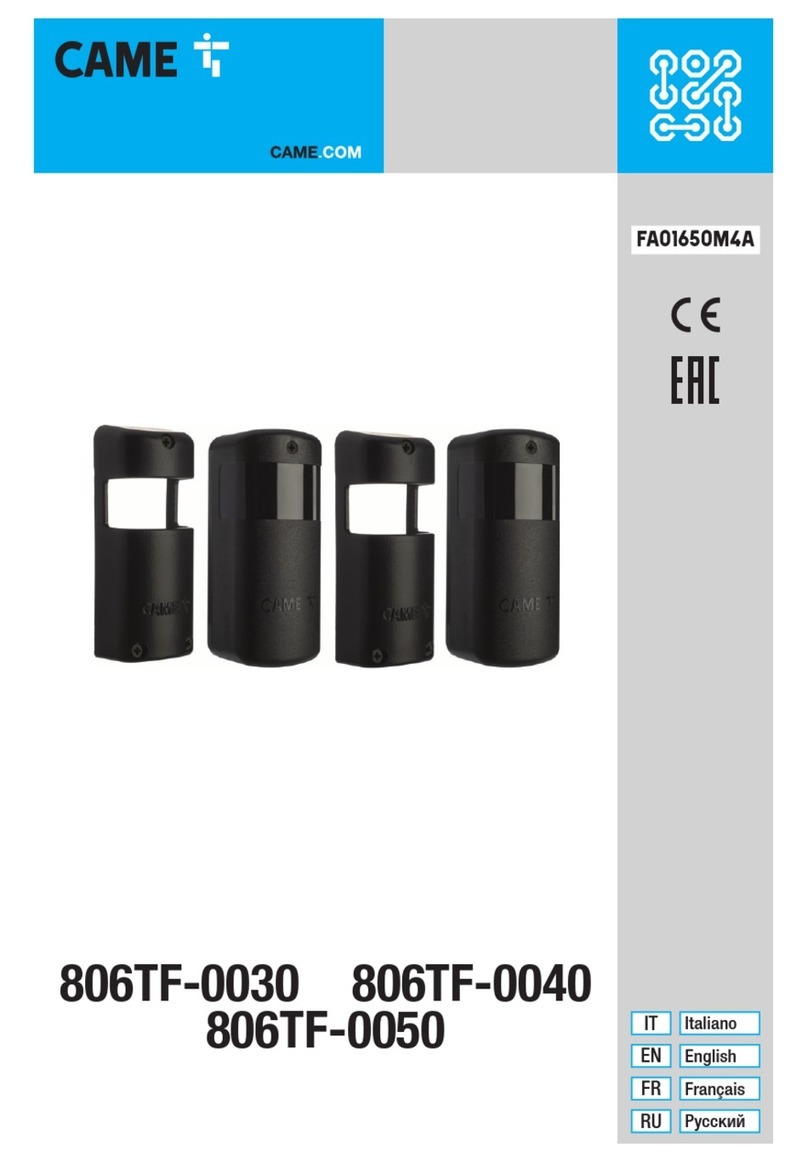
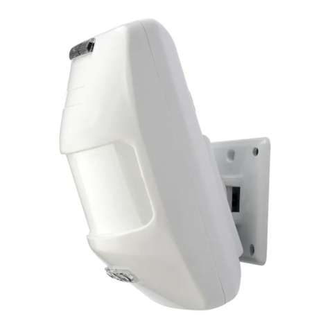
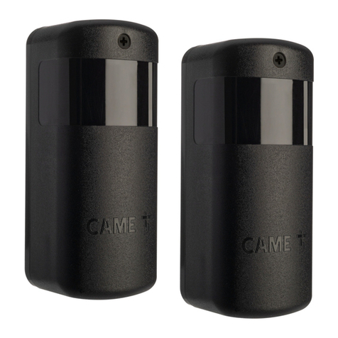
Photocell couples with infrared light, synchronised, externally orientable.
Any installation and improper use from that described in the manual, are prohibited.
Components 🅰
1. Cover Base
2. Rotating support
3. Electronic Circuit board
4. Attachment for rotating support
5. Attachment screws for rotating support
Part description 🅱
ⓐJP range of the Tx (20 m default)
ⓑDIP TX
ⓒOperation LED:
- SY not connected (🅲and 🅳), fast flashing (TX working).
- SY connected (🅴), slow flashing (synchronized
photocells), fast flashing (photocells not synchronized).
ⓓ SY: connection of more than 2 couples of photocells
(max 8 couples).
ⓔ DIP RX
ⓕLED quality of alignment: 1 flash not sucient, 2
sucient, 3 good, 4 excellent.
ⓖLED output activated.
ⓗJOUT: set up of the output (NC).
Technical data
Type 806TF-0030 806TF-0040 806TF-0050
Infrared range Max (m) 20 20 -
Wave length (nm) 940 940 -
Power Supply (V-50/60 Hz) 12-24 AC-DC 12-24 AC-DC -
Consumption of the 24V relay (mA) 500 500 -
Consumption at 24Vac (mA) <40 <40 -
Protection class casing (IP) 54 54 -
Isolation class III III -
Operating Temperature (°C) -20 ÷ 55 -20 ÷ 55 -
Dimensions (mm) 46x37x108 52x39x145 52x39x145
Material PC PC - Aluminium Aluminium
Installation
- Pierce the casing in order ① to run through the cables.
- Determinate the direction of the electronic circuit board ③ possibly 180° on the vertical axis, and 10° on the horizontal axis.
- Attach with the screws ⑤the rotating block support ②and the electronic circuit board ③.
- Attach with the screws provided ⑦the frontal part ⑥.
Connection
🅲Connection of one photocell.
🅳Connection of two photocells*.
🅴Connection of more than two pairs of photocell (max 8 couples).
* Install alternately TX and RX and program, each photocell with an ID address (DIP).
For the output contacts OUT check the connections and the manual function of the Came control panel.
ⓘ Connect the photocell to the services of the Came control.
Synchronisation
For the installation of more than 2 couples of photocells, it is necessary to connect the terminal SY between the transmitters
🅴
and program, each photocell with an ID address (DIP).
6. Box Cover
7. Attachment screws for cover
8. Anti-Vandal cover
9. Anti-vandal cover attachment screws
806TF-0040 = (806TF-0030) + (806TF-0050)
FRANÇAIS
Avertissements
– Il est nécessaire de lire toutes les instructions avant d'eectuer l'installation. Et faire des intervention comme indiquée par le
fabbricant . – L’installation e la programmation e la mise en service et la maintenance doivent être eectué par du personnel
qualifié selon les normes en vigueur. – Mettre des vêtements et chaussurer antistatiques en cas d’intervention sur la platine. –
Le produit a été crée uniquement pour l’utilisation pour le quel il est étudie et chaque utilisation est dangereux. – Le fabbricant
décline toute responsabilité pour les dommages dérivant de utilisation incorrects, erronées, excessif. – Vérifie même les
avertissements indiquées sur la notice d’installation e d’utisation de l’automatisme pour le quel le produit est associé. –
Afin d’éviter par erreur des contacts avec des partie sous tension, positioner le boîtier extérieur de l’automatisme après le
branchement du produit. – Dans l’utilisation du produit il ne faut pas permettre aux personnes, même des enfants d’être
proche de l’installation. – Il ne faut pas utiliser le produit en case mauvaises conditions météorologiques. – Le fabbriquant
CAME SPA, declaire que le produit écrit dans la notice est conforme à la directive 2014/53/UE. - Le texte complet de la
déclaration de conformità Ue est disponible dans le site internet: www.came.com.
MISE AU REBUT ET ELIMINATION - Les composants d’emballage (carton, plastique etc.) sont des dèchets ordinaires.
Les composants du produit (métal, cartes electroniques, piles etc) ,sont séparées et déchets. Pour le mise au rebut il faut
vérifier les règlements locaux.
NE PAS JETER!Respecter l'environnement
Le fabbricant se réserve le droit d’apporter des modifications aux produits à tout moment si elle le jugera nécessaire sans
proavi.
Dimensions, si pas spéfié, sont en mm.
Les photos de la notice sont uniquement pour information.
Description
Pareil de photocellule à infrarouge synchronisation orientrable à extérieur.
Chaque installation et utilisation selon indiqué sont considérées interdit.
Composants 🅰
1. Base du boîtier
2. Support giratoire
3. Carte électronique
4. Support de fixation giratoire
5. Vis de fixation pour suport giratoire
Description du partie 🅱
ⓐJP porté de l’émetteur (20 m default)
ⓑDIP TX
ⓒLED de fonctionnement :
- sans SY connecté (🅲et 🅳), clignotement rapide (TX en
marche).
- SY connecté (🅴), clignotement lent (photocellules
synchronisées), clignotement rapide (photocellules non
synchronisées).
ⓓ SY: branchement pour installation supérieur avec deux
pareils (max 8 pareils).
ⓔ DIP RX
ⓕLED qualité d’alignement: 1 clignote pas susant, 2
clignotes susant, 3 bon, 4 excellent.
ⓖLED sortie activée.
ⓗJOUT programmation sortie (NC défault).
Données techniques
Version 806TF-0030 806TF-0040 806TF-0050
Porté infrarouge Max (m) 20 20 -
Longeur d’onde (nm) 940 940 -
Alimentatiom (V-50/60 Hz) 12-24 AC-DC 12-24 AC-DC -
Courant absorbé relay à 24V (mA) 500 500 -
Courant abosorbé à 24Vac (mA) <40 <40 -
Indice de protection boîtier (IP) 54 54 -
Classe d’isolation III III -
Température de fonctionnement (°C) -20 ÷ 55 -20 ÷ 55 -
Dimensions (mm) 46x37x108 52x39x145 52x39x145
Matériau PC PC - Aluminium Aluminium
Installation
- Faire un trou sur le boîtier ① pour faire passer les câbles.
- Il faut orienter la carte életronique ③ possibilité du rayon à 180° horizontal et 10° vertical.
- Fixer les vis ⑤avec le support giratoire ②et la carte électronique ③.
- Fixer avec la vis fourni ⑦la partie frontale ⑥.
Branchements
🅲Branchement de 1 pareil de photocellule.
🅳Branchement de 2 pareils de photocellules*.
🅴Branchement des plusieurs pareils (max 8 pareils).
* Installer alternativement émetteur (TX) et recepteur (RX) et programmer chaque photocellule avec le propre adresse (DIP).
Pour les contacts de sortie OUT, vérifier toujours les indications des branchements et fonctions de la platine CAME choisi.
ⓘ Branchement photocellule au test des services de la platine CAME.
Synchronisation
Pour l’installation des plus de 2 pareils de photocellules, i est nécessaire de brancher le bornier SY entre les émetteurs 🅴
et programmer chaque photocellule avec le propre adresse (DIP).
6. Couvercle du boîtier
7. Vis de fixation du couvercle
8. Couvercle antivandal
9. Vis de fixation pour couvercle antivandal
806TF-0040 = (806TF-0030) + (806TF-0050)
РУССКИЙ
Предупреждение
– Внимательно прочитайте инструкцию передна чалом установки и выполните действия, указанные производителем
– Установка, программирование, ввод в эксплуатацию и техническое обслуживание должны выполняться
квалифицированным и опытным персоналом и в полном соответствии с действующими нормами. – Используйте
антистатическую одежду и обувь при работе с электронной платой. – Это изделие должно использоваться
исключительно по назначению. Любое другое применение не допускается. – Фирма-изготовитель не несет никакой
ответственности за ущерб, нанесенный ненадлежащим, ошибочным или небрежным использованием изделия.
– Прочитайте также руководство по установке и эксплуатации оборудования, с которым устанавливается данное
изделие. – Чтобы избежать случайного контакта с токоведущими частями, установите внешний корпус автоматики
после подключения изделия. – Во время использования изделия не позволяйте людям, включая детей, приближаться
к автоматике и зоне маневрирования. – Не используйте изделие при наличии неблагоприятных погодных условий.
– Производитель CAME S.p.A. заявляет, что изделие, описанное в данном руководстве, соответствует требованиям
Директивы 2014/53/EU. – Полный текст декларации о соответствии требованиям ЕС доступен по следующему
интернет-адресу: www.came.com.
РЕКОМЕНДАЦИИ ПО УТИЛИЗАЦИИ – Упаковочные компоненты (картон, пластмасса и т. д.) –твердые отходы,
утилизируемые без каких-либо специфических трудностей. Компоненты изделия (металлические детали,
электронные платы, аккумуляторы и т. д.) должны быть разделены и дифференцированы. Утилизацию необходимо
проводить в соответствии с действующим законодательством, в которой производилась эксплуатация изделия.
НЕ ЗАГРЯЗНЯЙТЕ ОКРУЖАЮЩУЮ СРЕДУ!
Содержание данной инструкции может быть изменено в любое время и без предварительного уведомления.
Все размеры даны в миллиметрах, если не указано иное.
Иллюстрации в данном руководстве носят общий характер.
Описание
Комплект синхронизированных инфракрасных фотоэлементов для наружного использования.
Запрещается использовать устройство не по назначению и устанавливать его методами, отличными от
описанных в настоящей инструкции.
Компоненты 🅰
1. Основание корпуса
2. Вращающаяся опора
3. Электронная плата
4. Крепление вращающейся опоры
5. Крепежные винты вращающейся опоры
Описание компонентов 🅱
ⓐПеремычка дальности действия JP (20 м по
умолчанию)
ⓑDIP-переключатели передатчика TX
ⓒСветодиоды синхронизации:
- без подключения SY (🅲и 🅳), быстрое мигание (TX
работает).
- с подключением SY (🅴), медленное мигание
(фотоэлементы синхронизированы), быстрое мигание
(фотоэлементы не синхронизированы)
ⓓ SY: контакт для синхронизации фотоэлементов при
установке более 2 пар (макс. 8 пар).
ⓔDIP-переключатели приемника RX
ⓕКачество направленности фотоэлементов: мигание
- 1 плохое, 2 достаточное, 3 хорошее, 4 отличное.
ⓖИндикатор состояния выходных контактов.
ⓗПеремычка установки типа выходных контактов
JOUT (по умолчанию NC).
Технические характеристики
Tип 806TF-0030 806TF-0040 806TF-0050
Инфракрасный диапазон макс (м) 20 20 -
Длина волны (нм) 940 940 -
Электропитание (В,50/60 Гц) ~/= 12-24 ~/= 12-24 -
Нагрузочная способность реле 24 В (мА) 500 500 -
Потребляемый ток при ~ 24 В (мА) <40 <40 -
Класс защиты (IP) 54 54 -
Класс изоляции III III -
Диапазон рабочих температур (°С) -20 ÷ 55 -20 ÷ 55 -
Габаритные размеры (мм) 46x37x108 52x39x145 52x39x145
Материал: PC PC - алюминий алюминий
Mонтаж
- Просверлите корпус ①для проводки кабелей.
- Определите ориентацию электронной платы ③возможный угол поворота 180 ° по горизонтальной оси и 10 °
по вертикальной.
- Закрепите вращающийся опорный блок ②и электронную плату ③, как показано на рисунках ⑤.
- Закрепите переднию часть ⑥ с помощью прилагаемого винта ⑦.
Подключение
🅲Подключение 1 пары фотоэлементов.
🅳Подключение 2 пар фотоэлементов*.
🅴Подключение нескольких пар фотоэлементов (до 8 пар).
* Установите передатчики ТХ с разных сторон и выставьте для каждой пары собственный адрес (DIP-
переключателями).
Всегда проверяйте соответствие типа выходных контактов OUT и контактов подключения фотоэлементов на
плате управления Came в соответствующем руководстве.
ⓘПодключение фотоэлементов к плате управления Came с функцией самодиагностики.
Синхронизация
Для установки больше 2 пар фотоэлементов необходимо подключить клеммник SY между различными
передатчиками 🅴и установить для каждой пары свой собственный адрес (DIP-переключателями).
6. Крышка корпуса
7. Крепежный винт крышки
8. Антивандальная крышка
9. Крепежные винты антивандальнойк рышки
806TF-0040 = (806TF-0030) + (806TF-0050)


