PM 1002499 000 00 Device handbook SIRAX BT5500 4/28
1.9 Disposal
Device may only be disposed in a professional manner!
The disposal of devices and components may only be realised in accordance with good professional practice observing the
country-specifi c regulations. Incorrect disposal can cause environmental risks.
1.10 Return
All devices delivered to Camille Bauer Metrawatt AG shall be free of any hazardous contaminants (acids, lyes, solutions, etc.).
Use original packaging or suitable transport packaging to return the device.
Damage by returning
Damages caused by improper returning, no warranties or guarantees can be given.
2. Introduction
2.1 Purpose of this document
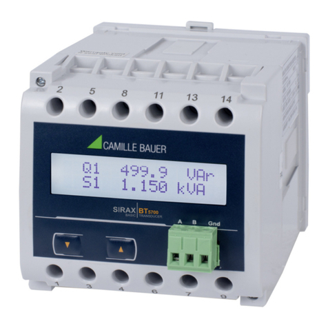
This document describes the programmable multi-function transducer SIRAX BT5500. It is intended to be used by Installers and commissioners,
Service and maintenance personnel, Planner.
Scope
This handbook is valid for all versions of the programmable multi-function transducer SIRAX BT5500. Some of the functions described in this
document are available only, if the necessary optional components are included in the device.
Required knowledge
A general knowledge in the field of electrical engineering is required. For assembly and installation of the device knowledge of applicable national
safety regulations and installation standard is required.
2.2 Scope of supply
• Programmable multi-function transducer SIRAX BT5500 with mounting kit
• Safety instructions (multiple languages)
2.3 Further documents
The following documents are provided electronically via www.camillebauer.com:
• Datasheet (ge, en)
• Safety instructions (multiple languages)
• Operating manual (ge, en)
3. Functional description
The SIRAX BT5500 is a programmable multifunctional transducer for measuring parameters in a three-phase 3- or 4-wire AC network. It ensures
the conversion of measured values into analog standard signals. The output signals are galvanically isolated from the input signals and the power
supply.
It can be parameterized via the RS485 interface with Modbus RTU or via the USB interface with the configuration software. The relay outputs signal
the overflow of the selected measured variables and the pulse output can be used to monitor the consumption of active energy.
3.1 Quantities measured and calculated
• 3-phase mean voltage …………………… U • Reactive/active ratio of power factors……… tg1, tg2, tg3
• Phase voltages ………………………… U1, U2, U3 • Active mean power (e.g. 150 min) ………… Pav
• Phase-to-phase voltages ………………… U12, U23, U31 • Voltage values THD ……………………… U1, U2, U3
• Phase-to-phase mean voltage …………… UPP • Current values THD ……………………… I1, I2, I3
• 3-phase mean current …………………… I • Phase values 1, 2, 3
• Phase currents ………………………… I1, I2, I3 • 3-phase values cos…………………… cos
• 3-phase active, reactive and apparent powers P, Q, S • phase values cos……………………… cos1, cos2, cos3
• Phase active powers …………………… P1, P2, P3 • Calculated current in the neutral cunductor wire In
• Phase reactive powers …………………… Q1, Q2, Q3 • 3-phase active and reactive energy ……… Ept, Eqt
• Phase apparent powers ………………… S1, S2, S3 • Frequency ……………………………… f
• 3-phase mean power factors …………… Pf, tg• Energy consumption - power guard ……… Pord
