Carbest 851320 Installation instructions

MPPT SOLAR-LADEREGLER
MPPT SOLAR CHARGE DEVICE
851320
DE – BENUTZERHANDBUCH
UK – USER‘S INSTRUCTION
FR – MANUEL D‘UTILISATION
IT – MANUALE D‘ISTRUZIONI
NL – INSTUCTIEHANDLEIDING
FI – KÄYTTÖOHJE
SE – ANVÄNDARMANUAL
DK – BRUGERHÅNDBOG

2
Carbest MPPT Solar-Laderegler|MPPT Solar Charge Device | 851320DE
VIELEN DANK, DASS SIE SICH FÜR UNSER PRODUKT ENTSCHIEDEN HABEN!
Bitte lesen Sie diese Gebrauchsanweisung vor der Inbetriebnahme sorgfältig durch und bewahren Sie
die Gebrauchsanweisung zum späteren Nachschlagen auf.
INHALTSVERZEICHNIS
1. Einleitung..........................................................................................................................................2
2. Eigenschaften ...................................................................................................................................3
3. Installation .......................................................................................................................................4
4. Auswahl der Ladekurve.....................................................................................................................5
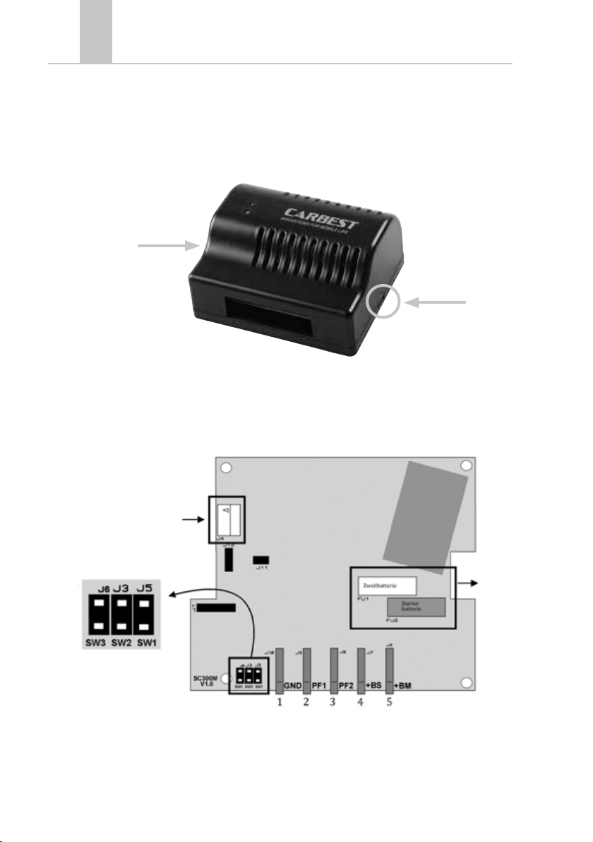
5. Anschlussschema.............................................................................................................................7
6. Betrieb. ............................................................................................................................................8
7. Auswechselung der Sicherungen.......................................................................................................9
8. Technische Merkmale.......................................................................................................................9
9. F. A .Q.................................................................................................................................................9
1. EINLEITUNG
Der Carbest MPPT Solar-Laderegler ist ein automatischer Spannungsregler, der die Leistung Ihrer
Solarmodule maximiert. Er ist in der Lage, die Eingangsleistung bis 300 W mit einem maximalen
Ladestrom von 20 A zu regulieren. Der Mikroprozessor kann bis zu vier Ladephasen ausführen,
einschließlich der wichtigen Desulfatierungsphase, die eine längere Lebensdauer der Batterie
garantiert.
WARNHINWEISE
• Kinder vom Gerät fernhalten
• Überprüfen Sie sorgfältig, dass Gerät, Kabel und Anschlüsse keine Schäden aufweisen.
• Installieren Sie das Gerät nicht in geschlossener Umgebung, sondern stets an gut belüfteten
Orten, um Überhitzungen und mögliche Brände zu vermeiden. Positionieren Sie das Gerät
nicht in der Nähe brennbarer Materialien (z.B.: Papier, Textilien usw.).
• Schützen Sie das Gerät vor Sonneneinstrahlung und direkten Wärmequellen.
• Um Störungen zu vermeiden, installieren und nutzen Sie das Gerät nicht in feuchter
Umgebung. Vermeiden Sie direkten Kontakt mit Wasser, anderen Flüssigkeiten oder Regen.
• Stellen Sie sicher, dass die Verkabelung des Fahrzeugs keine Schäden hat, um Stromschläge
und Brandgefahr zu vermeiden.
• Sollte das Geräte beschädigte Anschlusskabel oder einen ungeeigneten Kabelquerschnitt
haben, ist der Austausch notwendig. Rufen Sie hierzu einen qualifizierten Techniker.
• Benutzen Sie das Produkt nicht im Falle von Mängeln! Es ist strengsten verboten, das Gerät
zu öffnen. Reparaturen dürfen nur von einem qualifizierten Techniker unter der Benutzung von
Originalersatzteilen durchgeführt werden.
• Bewahren Sie die Gebrauchsanleitung in der Nähe des Geräts auf, um einfach Sicherheits-,
Gebrauchs- und Wartungsinformationen nachschlagen zu können.
• Die Abbildungen der Produkte sind nicht verbindlich und können deswegen in Farbe,
Abmessungen und Zubehör des Produkts abweichen.

3
Carbest MPPT Solar-Laderegler|MPPT Solar Charge Device | 851320DE
Dieses elektronische Produkt unterliegt der europäischen Richtlinie 2012/19/EU.
Beachten Sie die örtlichen Entsorgungsvorschriften, entsorgen Sie alte Produkte nicht
mit dem normalen Hausmüll. Die ordnungsgemäße Entsorgung nicht mehr verwendbarer
Produkte verhindert mögliche negative Folgen für die Umwelt und die Bevölkerung.
2. EIGENSCHAFTEN
Der Carbest MPPT Solar-Laderegler ist ein automatischer Spannungsregler, der die Ladung der
Zweitbatterien auf 12 V optimiert. Er unterstützt die folgenden Technologien: Blei- Säure-, Gel-, AGM-,
Lithium-Batterien für Photovoltaikanlagen mit 12 V Nennspannung.
Der Carbest MPPT Solar-Laderegler ermöglicht die Ladung der Zweitbatterie dank der Photovoltaik-
anlagen mit 12 V Nennspannung. Es besitzt zwei getrennte Eingänge für zwei Photovoltaikmodule,
mit jeweils einer Höchstleistung von 150 W und einer Nennspannung von 12 V.. Er besitzt auch
zwei Ausgänge: einen für die Zweitbatterie, einen für die Starterbatterie. Auf diese Weise werden
allen Fahrzeug-Batterien aufgeladen und erhalten. Es gibt zwei LEDs: die grüne zeigt die Ladung der
Zweitbatterie an, die gelbe zeigt die Ladung der Starterbatterie an. Das Aufleuchten der LEDs zeigt die
genaue Ladephase des Gerätes an. Man kann die Ladekurve durch drei Schalter konfigurieren. Es gibt
die Möglichkeit, einen Touchscreen Display zu verbinden, damit Sie die Ladedaten anzeigen und die
Ladekurve automatisch einstellen können.

4
Carbest MPPT Solar-Laderegler|MPPT Solar Charge Device | 851320DE
3. INSTALLATION
Zum Anschluss der elektrischen Kontakte sowie zur Einstellung der Ladekurve öffnen Sie den Deckel
des Geräts: Drücken Sie vorsichtig auf die seitlichen Federn (s. Abb. 1). Sie können auch einen kleinen
Schlitzschraubenzieher benutzen.
Wenn Sie den Deckel abgenommen haben, finden Sie die Leiterplatte und die Klemmen für den
Anschluss an die Photovoltaikmodule und die Batterien. Es ist außerdem möglich, die Ladekurve
auszuwählen und Sicherungen, wenn nötig, auszutauschen (s. Abb. 2).
ferngesteuertes
Display (optional)
Abbildung 2
Schalter
Sicher-
ungen
Abbildung 1
Öffnen des Gehäusedeckels

5
Carbest MPPT Solar-Laderegler|MPPT Solar Charge Device | 851320DE
4. AUSWAHL DER LADEKURVE
Durch die Schalter auf der Leiterplatte können Sie die geeignete Ladekurve für die installierte
Zweitbatterie auswählen. Wenn Sie Schalter SW3 einschalten, wird die Desulfatierungsphase
ausgelassen. Das ist nützlich, wenn Sie an Bord Steuerungen und Elektrogeräte haben, die mit einer
Spannung über 15 V beschädigt würden.
Hinweis: Die Standardeinstellung ist spezifisch für AGM-Batterien.
Hinweis: Die Auswahl des Servicebatterietyps und der Ausschluss der Desulfatierungsphase können
nur dann vom Display vorgenommen werden, wenn alle Auswahlbrücken auf der SC300M-Platine
entfernt wurden. Andernfalls werden stattdessen die auf dem MPPT Solar-Laderegler ausgewählten
Einstellungen verwendet.
Desulfatierung
an
Desulfatierung
aus (Standard)
SW3 -> Desulfatierung
4-LifePO4
SW1 e SW2 -> Auswahl der Ladekurve
3-WET2-GEL1-AGM (Standard)
Abbildung 3

6
Carbest MPPT Solar-Laderegler|MPPT Solar Charge Device | 851320DE
Konstanter Strom
Phase
4
Phase
3
Phase
2
Phase
1
Konstante Spannung Desulfatierung Erhaltungs-
ladung
Ladekurve Phase 2
Konstante Spannung [V]
Phase 3
Desulfatierung
Phase 4
Erhaltungsladung
AGM 14,8 V 15,8 V 13,7 V
GEL 14,2 V 15,8 V 13,4 V
Blei - Säure 14,4 V 15,8 V 13,4 V
LiFePO4 14,6 V / 13,7 V
Zusamenfassende Tabelle
Phase 1 Beständiger Strom
Phase 2 Beständige Spannung
Phase 3 Desulfatierung
Phase 4 Erhaltungsladung

7
Carbest MPPT Solar-Laderegler|MPPT Solar Charge Device | 851320DE
5. ANSCHLUSS-SCHEMA
PIN
1. Masse der Zweitbatterie (und der Photovoltaikmodule).
2. Pluspol des Photovoltaikmoduls Nummer 1 (PF1).
3. Pluspol des Photovoltaikmoduls Nummer 2 (PF2).
4. Pluspol der Zweitbatterie (oder gemeinsamer Pluspol der Anlage, wenn es einen PowerSwitch
oder I-Manager gibt).
5. Pluspol der Starterbatterie.
Der Kabelquerschnitt sollte mindestens von 4 mm2 - 6 mm2sein.
Anschlüsse

8
Carbest MPPT Solar-Laderegler|MPPT Solar Charge Device | 851320DE
6. BETRIEB
Die grünen und gelben LEDs zeigen die Ladephase der Zweitbatterie und/oder der Starterbatterie an.
Ein Blinken zeigt die Ladung an der ersten Phase an, zwei Blinken zeigen die Ladung an der zweiten
Phase usw.
Grüne LED blinkt: Ladevorgang der Zweitbatterie. Die Zweitbatterie wird in folgenden Fällen
aufgeladen:
1. Die Photovoltaikanlagen werden durch Sonne beschienen.
2. Die Spannung der Photovoltaikanlage ist höher als die Spannung der Batterie.
Gelbe LED blinkt: Ladevorgang der Starterbatterie. Das System lädt auch die Starterbatterie auf,
wenn:
1. Die Photovoltaikanlagen durch Sonne beschienen werden.
2. Die Zweitbatterie eine Ladung zwischen 80 % und 100 % hat.
3. Die Spannung der Starterbatterie niedriger als 12.5 V ist
Schnelles Blinken beider LEDs bei Sonneneinstrahlung bedeutet, dass die Sicherung der
Zweitbatterie durchgebrannt ist oder das die Spannung der Zweitbatterie niedriger als 6 V ist.
Hinweise: Wenn die Photovoltaikmodule die Stromversorgung aufgrund unzureichender Sonnenenergie
unterbrechen, bricht das System den Ladevorgang ab, indem es in den Standby-Modus wechselt. In
diesem Stadium blinken die LEDs nicht und der Gesamtverbrauch wird minimiert.
Ladephase Nr. des Blinkens
Grünes LED
1
2
3
4
Ladephase Nr. des Blinkens
Gelbes LED
1
2
3
4

9
Carbest MPPT Solar-Laderegler|MPPT Solar Charge Device | 851320DE
7. AUSWECHSELUNG DER SICHERUNGEN
Im Falle einer Beschädigung der Schutzsicherungen auf der Leiterplatte können diese durch die
mitgelieferten Original-Ersatzsicherungen ersetzt werden. Um an die Sicherungen zu gelangen,
entfernen Sie die Abdeckung des Geräts und befolgen Sie die Anweisungen im Kapitel Installation.
8. TECHNISCHE MERKMALE
Wenn Sie das Fahrzeug längere Zeit nicht benutzen, wird empfohlen, alle Lasten zu trennen, um den
Restverbrauch, der zur Entladung der Servicebatterie führt, vollständig zu unterbrechen.
9. F.A.Q.
• Kann ein einzelnes 200 W-Solarpanel an einem einzelnen Eingang (PF1 oder PF2) montiert
werden?
Sie können ein 200 W-Panel an den Eingang PF1 anschließen, vorausgesetzt, der andere
Eingang (PF2) ist kurzgeschlossen oder mit PF1 verbunden.
• Was ist die maximale unterstützte Spannung der Solarmodule?
Die maximale unterstützte Spannung ist 27 V.
• Ist eine Batteriespannung weit über 15 V normal, wenn der Regler eingeschaltet ist?
Das ist normal während der Desolfatierungsphase des Gerätes (Die LED blinkt 3 Mal).
Sie können diese Funktion deaktivieren, indem Sie den Schalter SW3, wie im Kapitel
„AUSWAHL DER LADEKURVE“ beschrieben, auswählen.
GEWÄHRLEISTUNG:
Der Gewährleistungszeitraum beträgt 36 Monate. Reimo behält sich das Recht vor, mögliche Fehler zu
beseitigen. Die Garantie wird für alle Schäden ausgeschlossen, die durch fehlerhafte Verwendung oder
unsachgemäße Handhabung entstanden sind.
Haftungsbeschränkungen:
Reimo ist in keinem Fall für Begleitschäden, Folgeschäden oder indirekte Schäden, Kosten, Ausgaben,
Nutzungsausfall oder Gewinnausfall haftbar. Der angegebene Verkaufspreis des Produkts stellt den ent-
sprechenden Betrag der Haftungsbeschränkung von Reimo dar.
Beschreibung Technische Merkmale
Eingangsspannung einziges Solar-Panel (VOS) 16 V – 27 V
PV-Eingänge 2
Maximale Spitzenleistung für jeden Eingang 150 W
Aktivierungsspannung des Starterladegerätes < 12,5 V
Nennspannung der Batterie 12 V
Verbrauch auf Stand-By 5 mA
Abmessungen L = 123 mm, B = 108 mm, H = 50 mm
Gewicht 0,40 kg (ohne Kabel)

10
Carbest MPPT Solar-Laderegler|MPPT Solar Charge Device | 851320UK
THANK YOU FOR CHOOSING OUR PRODUCT!
Please read this manual carefully before use and retain the instructions for future reference.
CONTENTS
1. Introduction..................................................................................................................................... 10
2. Features ......................................................................................................................................... 11
3. Installation ..................................................................................................................................... 12
4. Charging curve selection................................................................................................................. 13
5. Connection diagram ....................................................................................................................... 15
6. Operation....................................................................................................................................... 16
7. Fuses replacement.......................................................................................................................... 17
8. Technical features.......................................................................................................................... 17
9. F. A .Q............................................................................................................................................... 17
1. INTRODUCTION
The MPPT Solar Charge Device is the charge device that can maximize performances of your
photovoltaic modules.
It can handle up to 300 W in input, with a maximum charge of 20 A. The microprocessor can do up to
four charge phases, including the important desulphation phase which guarantees a longer battery life.
WARNINGS
• Keep the device out of reach for children.
• Carefully check the integrity of the device, connection cables, and connectors.
• To avoid overheating and fire risk, don’t install the device in a sealed environment,
always prefer ventilated areas. Do not place the device on easily inflammable surfaces or
environments (eg: paper, cloth, etc.).
• Protect the device from sunlight or direct heat sources.
• To avoid malfunctions Don’t install and use the device in very humid environments, in direct
contact with splashes of water, liquids or rain.
• To avoid the risk of electric shock and / or fire, make sure the vehicle power supply is in good
condition.
• In case of damaged or inadequate connection cables, make the replacement immediately,
using qualified technicians, DO NOT use the device with damaged cables and / or inadequate
section.
• In case of product anomalies do not use it! It is strictly forbidden to open the device. Repairs
can only be carried out by qualified technical personnel using original spare parts.
• Information in this manual can be changed without notice. Product images are purely
indicative and may not be perfectly representative of product features, differing in color, size,
or accessories.
• Keep the instruction manual near the device for easy access to essential safety, usage, and
maintenance information.

11
Carbest MPPT Solar-Laderegler|MPPT Solar Charge Device | 851320UK
This electronic product is subject to the European Directive 2012/19 / EU. Comply with
local waste disposal regulations, do not dispose of old products with normal household
waste. The proper disposal of products that can no longer be used prevents potential
negative consequences for the environment and for the population.
2. FEATURES
The MPPT Solar Charge Device is an automatic voltage regulator device that, in the standard version,
optimize recharge for 12 V service batteries. It supports the following types of technologies: lead acid,
GEL, AGM or Lithium and photovoltaic panels with 12 V rated voltage.
The MPPT Solar Charge Device allows the recharge of the auxiliary batteries using photovoltaic
panels with rated voltage of 12 V. It has two separate inputs for two photovoltaic panels up to 150Wp
maximum power each, with 12 V rated voltage.The system has two outputs: one for the auxiliary
batteries and the other one for the starting battery, thus allowing the battery to be charged and
maintained. Two indication LEDs (green and yellow) one for charging the auxiliary batteries, the other
for charging the starting battery. The LEDs number of flashes also indicate the exact charging phase.
The charging curve is selectable by three jumpers. Touch screen connection ready, useful to show
charging data and automatic charging curve setting.

12
Carbest MPPT Solar-Laderegler|MPPT Solar Charge Device | 851320UK
3. INSTALLATION
To make the electrical connection comfortable and set the right charging curve, open the device
cover by pressing moderately and carefully the tabs placed on both sides on the device, using a small
screwdriver.
Once the cover is removed you have direct access to the PCB, then to the FASTON for connecting
the device to photovoltaic panels and batteries; It is also possible to select the charging curve and to
replace the fuses (if necessary) as shown in the following figure (fig.2).
remote display
(optional)
Figure 2
jumpers
fuses

13
Carbest MPPT Solar-Laderegler|MPPT Solar Charge Device | 851320UK
4. CHARGING CURVE SELECTION
The jumpers on the PCB allows to select the appropriate charging curve for the installed auxiliary
battery. The Jumper SW3, if connected, excludes the desulphation phase from the charging curve,
which is useful if there are on-board control units and household appliances sensitive to voltages
greater than 15 V.
Note: The default setting is specific for AGM battery.
Note: the auxiliary battery type selection and the desulphation phase exclusion can be set by the Dis-
play only if all the selection jumpers have been removed on the SC300M board, otherwise the settings
selected on the MPPT Solar Charge Device will be used instead.
Desulphation
enabled
Desulphation
disabled (default)
SW3 -> Desulphation switch
4-LifePO4
SW1 e SW2 -> Auswahl der Ladekurve
3-WET2-GEL1-AGM (default)
Figure 3

14
Carbest MPPT Solar-Laderegler|MPPT Solar Charge Device | 851320UK
Constant current
Phase
4
Phase
3
Phase
2
Phase
1
constant voltage desulphation mainthenance
Charging Curve Phase 2
constant voltage [V]
Phase 3
desulphation
Phase 4
mainthenance
AGM 14,8 V 15,8 V 13,7 V
GEL 14,2 V 15,8 V 13,4 V
wet
(LEAD ACID)
14,4 V 15,8 V 13,4 V
LiFePO4 14,6 V / 13,7 V
Summary table
Phase 1 Constant current
Phase 2 Constant voltage
Phase 3 desulphation
Phase 4 mainthenance

15
Carbest MPPT Solar-Laderegler|MPPT Solar Charge Device | 851320UK
5. CONNECTION DIAGRAM
PIN
1. Auxiliary battery (and photovoltaic panels) ground.
2. Positive photovoltaic panel No. 1 (PF1).
3. Positive photovoltaic panel No. 2 (PF2).
4. Positive auxiliary battery (or positive common system if there is a Power Switch or iManager).
5. Starting Battery Positive.
It is recommended to use cables of at least 4 mm2 - 6 mm2.
Connections:

16
Carbest MPPT Solar-Laderegler|MPPT Solar Charge Device | 851320UK
6. OPERATION
Two LEDs (green and yellow) indicate the active charge status on one or both of the batteries (service
and startup); the flashing series emitted by the LED indicates the charging phase in which the battery
is located: 1 blink will match the first phase, 2 blinks at the second and so on…
The flashing green LED indicates „service battery charging”. the system delivers charges to the service
batteries if:
1. photovoltaic panels are irradiated by sun
2. the voltage supplied by the panel is higher than that of the battery itself.
The flashing yellow LED indicates „start battery charging”. the system delivers charges to the start
battery if:
1. photovoltaic panels are irradiated by sun
2. the service battery in charged between 80% and 100%
3. the start battery voltage in under 12,5 V
A fast blink of both LEDs (with an active solar panel) signals an abnormality due to service
battery fuse failure or that the service battery voltage is below 6 V.
Note: When the photovoltaic panels interrupts power supply due to insufficient solar power, the system
terminates charging by entering standby mode, at this stage the LEDs will not blink and the overall
consumption will be minimized.
Charging phase N° flashes
green LED
1
2
3
4
Charging phase N° flashes
yellow LED
1
2
3
4

17
Carbest MPPT Solar-Laderegler|MPPT Solar Charge Device | 851320UK
7. FUSES REPLACEMENT
In case of damage of the protection fuses on the PCB, it’s possible to replace them with the original
spare fuses provided. To reach the fuses, remove the cover of the device, and follow the instructions
in the installation section.
8. TECHNICAL FEATURES
If you do not use the vehicle for a long time, it’s recommended to disconnect all the loads to
completely interrupt any residual consumption that may discharge the service battery.
9. F.A.Q.
• Is it possible to mount a single 200 W panel on a single input (PF1 or PF2)?
You can connect a 200 W panel such as PF1, provided the other channel (PF2) is shorted or
joined with PF1.
• What is the maximum voltage of the panel accepted?
Maximum voltage is 27 V.
• A far above 15 V battery voltage (with the sun regulator active) is normal?
Yes, it is normal when the device is in desulphation (the LED blinks 3 times). you can still
disable this function by selecting the jumper SW3 as described in the “Charging curve
selection“ section.
WARRANTY:
The warranty period is 36 months. Reimo reserves the right to rectify eventual defaults. The guarantee is
excluded for all damages caused by faulty use or improper handling.
Liability limitations:
In no case Reimo will be reliable for collateral-, secondary- or indirect damages, costs, expenditure, mis-
sed benefits or missed earnings. The indicated sales price of the product is representing the equivalent
value of Reimo’s liability limitations.
Description Technical features
Single Input Voltage Photovoltaic Panel Voltage
(VOS)
16 V – 27 V
Photovoltaic panel 2
Maximum peak power for each input 150 W
Activation voltage charge star battery < 12,5 V
Nominal voltage 12 V
Stand-by consumption 5 mA
Size L = 123 mm, B = 108 mm, H = 50 mm
Mass 0,40 kg (cables not included)

REIMO REISEMOBIL-CENTER GMBH
63329 EGELSBACH · BOSCHRING 10
GERMANY · WWW.REIMO.COM
MADE IN CHINA
REIMO REISEMOBIL-CENTER GMBH
63329 EGELSBACH · BOSCHRING 10
GERMANY · WWW.REIMO.COM
MADE IN CHINA
www.reimo.com © 2018
Table of contents
Languages:
Other Carbest Batteries Charger manuals
Popular Batteries Charger manuals by other brands

TecMate
TecMate Optimate2 TM422 Instructions for use

Innogy
Innogy eBox professional Instructions for use

Boston Scientific
Boston Scientific Vercise DB-64126 Handbook

STRIKEMASTER
STRIKEMASTER LITHIUM 24V BATTERY CHARGING BASE quick start guide

Lenmar
Lenmar Mach 1 manual

Rayovac
Rayovac PS3 instruction manual