caron 6010 User manual

CARON 6000 SERIES
ENVIRONMENTAL TEST CHAMBERS
MODELS 6010, 6011, 6012, 6030, 6031, & 6032
OPERATIONS MANUAL

6000 SERIES MANUAL_U.doc 12-12-07 2
TABLE OF CONTENTS
SE CTION
P AG E S
INTRODUCTION
.............................................................. 3
Symbo s and Warnings......................................................... 3
SPECIFICATIONS ........................................................... 5
INSTALLATION ...............................................................
7
Chamber Location ................................................................ 7
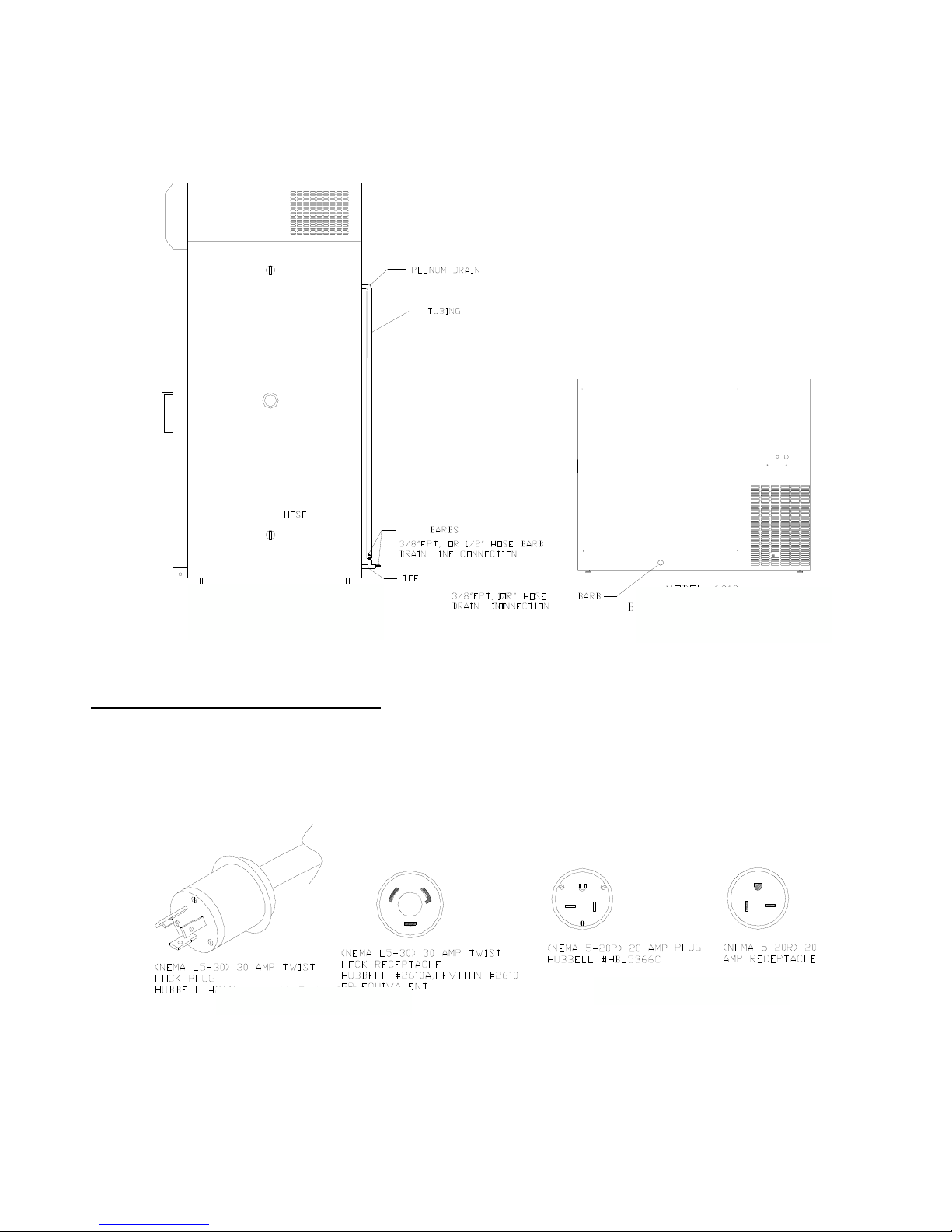
Drain Connection .................................................................. 8
Power ................................................................................... 8
OPERATION
.................................................................. 10
CONTROLLERS
...................................................................... 12
Temperature Deviation A arm ............................................. 12
OPTIONS . ..................................................................... 13
Humidity System & Contro er ............................................. 13
Humidity Contro er Ca ibration ........................................... 14
Humidity Water In et ........................................................... 14
Diurna Lighting System...................................................... 15
Heat ess Dryer Package ..................................................... 16
Dryer Package Insta ation ....................................... 16
Dryer Package Testing & Adjustments .................... 17
Circu ar Chart Recorder...................................................... 18
Setup, Insta ation .................................................... 18
Routine Maintenance ............................................... 21
Contact C osure Timer System ........................................... 22
Condensate Recircu ating System...................................... 23
Remote A arm Contact ....................................................... 25
Product Temperature Safety............................................... 25
Computer Communications ................................................ 12
Defrost Package............................................................................ 26
MAINTENANCE
....................................................................... 27
TROUBLESHOOTING
GUIDE
..............................................
29
APPENDIX A – Watlow 96
Co troller
...............................
30
Genera Contro er Operation.............................................. 30
Light & Contact Timer, Communications ............................ 31
APPENDIX B – Watlow SD
Co troller
..............................
32
APPENDIX C – 230 V Optio al
U it
.................................. 33
Light & Contact Timer ......................................................... 33
APPENDIX D – Declaratio of
Co forma ce
................ 34

INTRODUCTION
The CARON 6010 & 6030 series Environmenta Test Chambers provide mu tip e capabi ities to
create repeatab e environmenta conditions for numerous app ications inc uding:
• Product she f ife
• Stabi ity and package testing
• Light exposure and temperature eva uation studies
• E ectronic component burn-in
• TAPPI testing
• Photostabi ity
• P ant growth
• Insect rearing
These chambers uti ize environmenta y friend y HFC refrigerant and CFC-Free insu ation, and is
designed to meet NEC, UL and CSA standards for safety and performance.
Contro ing the chamber temperature requires the abi ity to heat and coo . Heating of the chamber
is achieved by duct heaters, and coo ing is achieved by a direct expansion/vapor compression
refrigeration heat exchanger mounted in the duct, combined with horizonta airf ow pattern which
creates better air uniformity, and temperature contro .
A bi-moda contro er (sing e input - dua output) is necessary for proper contro of the system that
can drive the process variab e in either direction. The refrigeration system uses a sing e
condensing unit that wi a ow independent coo ing and dehumidification. This insures continuous,
safe and re iab e operation of the compressor even when no coo ing is required. This a so
prevents the compressor from rapid cyc ing “on” and “off” which shortens the compressor ife.
SYMBOLS AND WARNINGS
Warning of hazardous area
Warning of dangerous electric voltage
Earth (ground) protective conductor
Local government may require proper electrical component disposal

CHAMBER CONSTRUCTION
The chamber is a custom designed sheet meta package. Exterior meta is Co d Ro ed Stee
(CRS) with a powder coat finish for corrosion resistance. The chamber interior is constructed from
304 stain ess stee , with a joints seam we ded. The chamber face connecting the interior to the
exterior is magnetic stain ess stee providing a sea ing surface for the magnetic gasketed exterior
door as we as improved corrosion resistance. The contro pane housing is constructed from
a uminum with a powder coat finish. The chamber is insu ated on a sides with fiberg ass
insu ation rated at 70
°
C.
SHELF CONSTRUCTION (STANDARD)
The chamber she ves are po ished, 304 stain ess stee wire formed.
REFRIGERATION SYSTEM
A bi-moda refrigeration system a ows for independent heating and coo ing. This system is now
used to rep ace the ess sophisticated type of refrigeration system which used heaters to buck
against the refrigeration system and assist in temperature contro . The new design a ows the
chamber to respond faster and contro s the chamber more efficient y at a constant temperature.
CONTROL SYSTEM
The contro system is comprised of a sing e channe , dua output contro er. On/off outputs are
used to drive heaters and coo ing so enoids.
SAFETIES
The CARON 6000 Series has a trip e redundancy safety system. A temperature a arm in the
temperature contro er sounds an a arm to a ert the end user to the condition. A therma snap
disk, high imit and a therma fuse are provided to prevent run-away heating of the unit. The
compressor and b ower motors are both protected by therma over oads. The Condenser fan
motor is impedance protected.

MODEL 6010 SPECIFICATIONS
Temperature Range without ights 5
°
C to 70
°
C
Temperature Range with ights 10
°
C to 70
°
C
Temperature Contro
± 0.1
°
C
Temperature Uniformity
± 0.3
°
C Re ative
Humidity 20 to 98% RH
∗
Humidity Contro
±
3%
Interior Dimensions 23”W x 25.8”D x 29.8”H
(58cm x 65.5cm x 75.7cm)
Exterior Dimensions 43.4”W x 30.6”D x 36”H
(110cm x 77.7cm x 91.4cm)
Work Space 10 cu.ft. (283.2 iters)
She ves
Number of she ves 4 Stain ess Stee , Wire Rod Standard
She f Spacing 1.5” on center (15 positions)
She f Size Each She f: 22.8”W x 25.4”D
(57.9cm x 64.5cm)
She f Area 4ft.2 each, 16ft.2 tota
Materia s / Finishes:
Interior Chamber - a Stain ess Stee
Interior door - Tempered g ass
Exterior Chamber - Co d Ro ed Stee and
Magnetic Stain ess Stee , Powder
Coat Finish
Exterior Door A uminum, Powder Coat Finish
Feet Adjustab e eve ing pads
E ectrica 115V/20A/60Hz (standard, 220V optiona )
Shipping Weight 400 bs.
Disp ay Reso ution:
Temperature 0.1
°
C
Re ative Humidity 1% RH
∗
RH
eve s imited by 4
°
C minimum dewpoint
Specifications were estab ished at 20
°
C with 50% RH ambient conditions.
Chamber
ambient
conditions
2 0
°
C to
25
°
C.
Exceeding
2 5
°
C
can
result
in
chamber
failure.
For he p with operation of the unit, ca Customer Service at 1-740-373-6809.

MODEL 6030 SPECIFICATIONS
Temperature Range without ights 5
°
C to 70
°
C
Temperature Range with ights* 10
°
C to 70
°
C
Temperature Contro
± 0.1
°
C
Temperature Uniformity
± 0.3
°
C
Re ative Humidity* 20 to 98% RH**
Humidity Contro *
±
2%
Interior Dimensions 30”W x 27.5”D x 63.5”H
(76.2cm x 69.9cm x 161.3cm)
Exterior Dimensions 36”W x 39”D x 90”H
(91.4cm x 99.1cm x 228.6cm)
Work Space 30 cu.Ft. (850 iters)
She ves
Number of she ves 5 Stain ess Stee , Wire Rod Standard
She f Spacing 1.5” on center (37 positions)
She f Size Each She f: 29.25”W x 26.5”D
(74.3cm x 67.3cm)
She f Area 5.4ft.2 each, 26.9ft.2 tota
Materia s / Finishes:
Interior Stain ess Stee
Exterior Meta with powder coated finish
Feet Adjustab e eve ing pads
E ectrica 115V/25A/60Hz 1Ph. (standard, 220V optiona )
Shipping Weight 750 b. (340kgs)
*Optiona items
**RH eve s imited by 4
°
C minimum dewpoint
Specifications were estab ished at 20
°
C with 50% RH ambient conditions.
Chamber
ambient
conditions
2 0
°
C to
25
°
C.
Exceeding
2 5
°
C
can
result
in
chamber
failure.
For he p with operation of the unit, ca Customer Service at 1-740-373-6809.

INSTALLATION
U packi g
This product has been comp ete y tested, c eaned and packed for shipment. Carefu y remove a
packing materia . P ease examine the chamber comp ete y. Shou d any damage be found, notify
the de ivering carrier immediate y.
Report any shortages to Customer Service at 1-740-373-6809.
Chamber Locatio
Chamber
ambient
conditions
20
°
C to
25
°
C.
Exceeding
25
°
C
can
result
in
chamber
failure.
The chamber must be ocated in a dry, c ean, and eve area. A ow a 4” c earance from the back
and top of the chamber for proper air circu ation and ease of insta ation. Locate the chamber in
an area out of direct sun ight and away from heating and coo ing ducts. The 6010 & 6030
chambers can exhaust 2500 BTU/hr (730 W) and 4000 BTU/hr (1170 W) respective y into the
surroundings. The figure be ow shows a side view of the chamber with air vent and access port
ocations.
Mode s
6030,
6031,
603 2 : Ti t the unit ½ of a eve ’s bubb e toward the back for proper water
drainage
Mode s
6010,
6011,
6012: Unit shou d be comp ete y eve for proper water drainage

Drai co ectio
Connect a 3/8” NPT drain ine to the drain connection ocated on the ower back side of the chamber. The figure
be ow shows the drain connection on the back of the chamber. For proper operation the drain hose shou d not be
kinked or bent. It shou d run down from the chamber and go into an open f oor drain.
Models 60 0, 60 1, 60 2
Right side of chamber
Models 6010, 6011, 6012
Back side of chamber
Power
PLEASE READ CAREFULLY!
For persona safety, this chamber must be proper y grounded.
The Power Cord of this chamber is equipped with a grounded p ug which mates with a
corresponding out et to minimize the possibi ity of e ectrica shock from the chamber. CARON
recommends that the chamber have a dedicated wa out et.
Models 60 0, 60 1, 60 2
Models 6010, 6011, 6012

INSTALLATION co t.
Co trol System
The contro system is comprised of a 1/16 DIN temperature contro er. The drawing be ow shows
the contro pane (exact contro er may vary). The disp ay pane consists of a power switch,
refrigeration switch, and a temperature contro er. The temperature contro er’s unit is degrees
Ce sius (
°
C). Refer to the figure be ow for the ayout for the indicator ights as detai ed be ow.
See appendix for contro er operating instructions.
2 0
.
0
CONTROL PANEL

OPERATION
1. Connect the drain ines, and power cord as instructed in the INSTALLATION section of this
manua . (See Appe dix C for additio al drai co ectio s. 6030 o ly)
2. Insert a she f c ips, and she ves. Check to see if they are proper y insta ed.
3. C ose the chamber door.
4. Insta rubber stopper in access port on right side of cabinet.
5. Turn on power switch ocated on the contro pane . This switch activates the heating unit and
temperature contro er. The temperature contro er wi sound an a arm. The temperature a arm
wi automatica y reset after a few seconds.
6. *Turn on the refrigeration switch when operating at setpoints be ow 35
°
C. This switch
activates the refrigeration system.
7. Set the temperature contro er to the desired setpoint. (See appendix if necessary).

8. Turn on the humidity switch. This switch activates the humidity system and the humidity
contro er. (with humidity option on y). Set the humidity contro er to the desired setpoint. (See
appendix if necessary).
During norma refrigeration operation, a soft “c icking” sound can be heard. This sound is the
resu t of the so enoid contro va ves switching in the refrigeration system.
Chamber Loadi g
Air circu ates through the chamber to maintain uniform conditions. When oading (putting product
into) the chamber, position samp es so air can f ow free y throughout the chamber. For best
temperature & humidity uniformity, keep samp es away from surfaces as isted in tab e be ow. Do
not put product on the f oor.
Mode Cei ing Back wa Side wa s Front / door
Between
she ves
6010, 6011, 6012 2 in (5 cm) 2 in (5 cm) 4.5 in (11 cm) 2 in (5 cm) 2 in (5 cm)
6030, 6031, 6032 6 in (15 cm) 6 in (15 cm) 3.5 in (9 cm) 3.5 in (9 cm) 3.5 in (9 cm)

CONTROLLERS
The temperature contro system is comprised of a sing e channe , dua output contro er. On/off
outputs are used to drive heaters and coo ing so enoids. An additiona contro er is used to contro
the humidity (if that option is ordered). Both contro ers are configured and tested at the factory to
ensure proper performance.
Contro er operating procedures and factory defau t settings are isted in the Appendix. Defau t is
temperature disp ay in ºC. For ºF, consu t factory for detai s. In addition, see the separate
contro er manua for more detai s on contro er operation, menus and avai ab e settings.
Due to individua circumstances, it maybe beneficia to modify the defau t settings to best suit an
app ications. Examp es inc ude a arm and communication settings.
NOTE: On power up, the temperature and humidity contro ers a ow the system one minute to
stabi ize prior to turning on outputs. Therefore it is norma for the unit not to turn on heating or
coo ing, or humidify for a fu minute on power up regard ess of set-points and cabinet conditions.
TEMPERATURE DEVIATION ALARM
A units are equipped with an a arm system that constant y monitors temperature to ensure the
user is notified if the cabinet goes into an a arm condition. Notification occurs via a RED indicator
LED and an audib e a arm. Temperature a arms wi occur once the a arm condition has been
present for 15 minutes. This de ay is in p ace to avoid nuisance a arms associated with door
openings.
Examp e of Deviation va ue:
Set point = 30
°
C
A arm high = 5
°
C
A arm ow = 3
°
C
∴
High A arm = 35
°
C and Low A arm = 27
°
C
NOTE: When powering up the chamber, if the actua interior chamber temperature varies from
the setpoint, immediate y set the deviation amount to a arge enough margin in order to a ow the
chamber to reach the temperature setpoint. If the deviation amount is too sma the a arm wi
sound unti the chamber is within the min / max deviation range. The temperature deviation a arm
is preset to 50°C above or be ow set point.

6010 & 6030
Humidity System
A bi-moda humidification system a ows for independent humidification and dehumidification. This
design provides contro over both the humidity injection system and the dehumidification system.
This system permits the chamber to respond faster as we as contro ing the chamber more
efficient y at a constant re ative humidity.
The Humidity Injection System uti izes atomizers to inject moisture into the chamber to achieve
humidity eve s of 98% RH. An extended ow end humidity eve of 20% RH is attainab e due to
the configuration of the refrigeration system ( imited by a minimum 4
°
C dew point). The atomizer
system is preferred over the boi er type system, since it wi not add heat to the chamber. The
added heat causes the system to work harder to maintain temperatures, especia y at ower eve s.
Humidity System Co trols
The humidity system is comprised of a 1/16 DIN contro er. The i ustration be ow shows the ayout
of the contro pane (contro er mode may vary). The disp ay pane consists of the standard
contro pane , in addition a humidity switch, and a re ative humidity contro er. The re ative
humidity contro er’s unit is %RH. Refer to the appendix for contro er detai s.
2 0
.
0
2 0
.
0
2 0
.
0

Humidity (Chromalox) Co troller Calibratio (for Watlow co trollers, see Appe dix A)
1. Remove the access pane (contro pane cover 6030), (right side pane 6010).
2. Find the 2” x 3” b ack uti ity box ocated adjacent to the wiring and in the service area.
(Behind fuse pane 6030, near cei ing 6010).
3. Inside the uti ity box is the humidity modu e.
4. S ow y adjust the BOTTOM humidity ca ibration pot to the desired ca ibration point as shown
on the humidity contro er readout.
Humidity Water I let
Mode
6030: Facing the back is a water connection in the upper right hand corner. The ¼” FPT
fitting is attached to a fi ter/strainer and pressure regu ator that is set at 40 PSI. Any type of ¼
MPT fitting can be used to connect to water supp y.
Mode
6010: Facing the back is a water connection in the ower right hand corner. The ¼ FPT
fitting is attached to a fi ter/strainer and pressure regu ator that is set at 40 PSI. Any type of ¼
MPT fitting can be used to connect to water supp y.

NOTE
Use o ly distilled or deio ized water with resistivity betwee 50kΩ-cm & 1 MΩ-cm a d pH
above 6.5. Usi g water outside this ra ge will void the warra ty.
Do not use water with ch oramines. Ch oramines can damage interna rubber gaskets and cause
a catastrophic eak.
Mode
6030: The two atomizing heads are ocated in the interior cei ing area which inject the
humidity into the chamber.
Mode
6010: The atomizing head is ocated on the eft side interior wa .
It is a so important to check and c ean the humidity water in et fi ter/strainer every 6 months. After
c eaning fi ter/strainer hand tighten bow onto housing, overtightening bow can cause cracks and
fi ter/strainer to eak
DIURNAL LIGHTING SYSTEM
The Diurna Lighting System, a so known as the Dua Setpoint/Light Cyc e Timer System
Mode 6032 consists of four (4) ight banks, with 2 ights per bank; one ight bank per she f on 4 of
the five she ves, and a timer.
Mode 6012 consists of two (2) ight banks, with 1 ight per bank; one ight bank per she f on 2 of
the four she ves, and a timer.
This system a ows the operator to simu ate Day/Night testing. The Switch wi turn both ight
banks on and off simu taneous y as we as operate the two setpoint temperature system. The
i ustration be ow is a ayout of the contro pane .
Note: For units equipped with ramping contro ers, the timer maybe used to trigger certain events
but does not necessari y switch between two set points. See contro er manua for detai s.
During operation of the Diurna Lighting System a second setpoint can be set in both the
temperature and humidity contro ers. This second setpoint wi be used as the DAY setpoint, or
when the ights are on. See appendix for procedures to set the second setpoints for the
temperature and humidity contro ers.
Note: Whe Timer/Lights switch is i “off” positio the Temperature, Humidity Co trollers
will default back to origi al setpoi ts SP.

TIMER
The circu ar timer on the ower contro pane shown above is for the operation of the dua
setpoint/ ight cyc e system. The timer is adjustab e at 15 minute interva s by depressing the cams
found on the outer ring of the timer.
SETTING THE TIMER:
a) The Timer is ocated on the contro pane as shown in the previous i ustration.
b) Depress the number of cams toward the timer’s center to fit the duration of your
program.
c) Set the timer dia to ref ect an entire day.
d) Turn on the Switch
LED STRIP LIGHTING
Chambers with optiona LED strip ighting inc ude a 24-hour ight cyc e timer. Can use with
ramping contro ers but not second set point.
HEATLESS DRYER PACKAGE
The Heat ess Dryer Package is designed to extend the operationa imits of CARON’s Series 6000
Environmenta Test Chamber to its minimum humidity contro point of 2% RH and improve the
dehumidification rate of the chamber. This is accomp ished by “purging” the chamber of its moist
air. The Dryer Package uti izes 90 to 100 PSI compressed air to operate.
A coa escent fi ter (with automatic drain) wi remove sma amounts of incoming moisture.
However, partic es of dirt or rust, as we as arge amounts of condensed moisture or oi that may
be in the compressed air ine feeding the dryer must be removed from the air stream before it
enters the dryer.
CARON recommends insta ing a pressure gauge prior to the dryer to air in monitoring system
pressures. The f ow meter shows the f ow rate of dry air entering the chamber. It is adjustab e by
the knob at the bottom of the meter. Maximum performance is obtained at 300 SCFH (or 5 CFM).
Operating the unit above this purge rate may decrease performance!!
On some mode s, a pressure regu ator is insta ed between the tower dryers and g ass f ow meter
to imit the pressure into the f ow meter. The regu ator shou d be set at a maximum of 100psi.
DRYER PACKAGE INSTALLATION
a) Attach the Dryer package to the exterior chamber with the pre-dri ed mounting ho es and
mounting hardware. Be sure to secure each tower.

b) Attach the 3/8” ID c ear tubing to the out et of the f ow meter. Secure tubing with the hose
c amp provided.
c) Connect compressed air (either from house air or other compressed air source) to the fitting
abe ed “air supp y in et”.
NOTE: THE AIR SOURCE MUST BE OIL-FREE AND WATER-FREE AND FILTERED TO 10
MICRONS MINIMUM.
d) P ug in the air regu ating so enoid ine cord into the matching receptac e ocated above the
dryer mounting bracket.
AIR OUTLET
PLUG PRESSURE
REGULATOR
KNOB
AIR INLET PRESSURE
REGULATOR DIAL
PRESSURE
REGULATOR DIAL
TESTING AND ADJUSTMENTS
Connect the cord to the proper receptac e as mentioned above, and turn the humidity power
switch “on”.
Turn on air supp y. Be certain that the air pressure into the in et side of the dryer assemb y is set
at a minimum of 90 PSI and not above a maximum of 100 PSI.
To set the pressure regu ator
1. C ose the air f ow adjustment knob
2. Set the chamber to 0% humidity (fu dehumidification)
3. Adjust the pressure regu ator adjustment knob to 90 psi
To set the air f ow rate

1. Set the f ow meter on the dryer assemb y to approximate y 300 SCFH. Watch the humidity
disp ay to see that the % RH is moving down to the specified setpoint.
A ow sufficient time for the chamber to stabi ize when setting up and making adjustments,
especia y if the chamber has been running with high humidity eve s. Running the chamber at
higher than ambient humidity eve s can cause moisture to co ect in a areas of the chamber
inc uding sensors and other components. This moisture must be removed before actua tests can
proceed at accurate, ower than ambient humidity eve s.
CIRCULAR CHART RECORDER,
The Honeywe DR 4300 Genera Purpose Circu ar Chart Recorder uses re iab e microprocessor
operation to generate dependab e pen drawn ana og traces on preprinted 10-inch (250 mm)
charts.
The two-pen mode (RCDR103) accepts inputs from a temperature sensor and a humidity sensor.
The sing e-pen mode RCDR107 records temperature on y.
temperature sensor is a high y accurate RTD. The humidity sensor is a Vaisa a or equa which
uti izes the Humicap
®
sensor to measure re ative humidity. The recorder uses disposab e fiber-tip
ink cartridges for dependab e recording with minimum maintenance. The recorders are housed in
a mo ded case with a g ass windowed, gray gasketed door which protects interna components
whi e a owing easy access to the chart.
Input samp es are taken at a rate of 2 times every 1.3 seconds. Each samp e is amp ified and
then converted to a digita signa which is iso ated and passed to the microprocessor. Ana og and
digita fi ters with fixed time constraints provide input signa smoothing as required. Standard
factory set up for chart speed is 7 day operation. Refer to the Chart Recorder’s User’s Manua to
change the chart speed settings for various chart speeds.

Mount the recorder by using the a ready insta ed bracket.
There are three factory dri ed ho es ocated on the right side of chamber facing the front of
chamber.
Using the factory supp ied screws, screw the recorder to the side of the chamber.
Model 60 0, 60 1, 60 2
Right side
Model 6010, 6011, 6012
Right side
NOTE: Before applyi g power to the recorder, complete these prelimi ary preparatio
tasks to prepare the recorder for operatio .
NEVER
ATTEMPT
TO
ACCESS
COMPONENTS
INSIDE
THE
RECORDER
CASE
WITH
POWER
APPLIED.
The Vaisa a RH Sensor is wired to the Humidity contro er in the chamber for 0-5 Vo t actuation.
An individua 100Ω RTD Temperature sensor is wired to the Recorder.
In order to connect the Humidity and temperature sensor to the recorder, refer to the figures be ow
to perform the fo owing procedures:

a) Locate the wires fastened to the side of the chamber, these are the temperature and
humidity sensor wires.
b) Push the button on the recorder door and swing the door open.
c) Loosen the captive screw in the chart p ate and swing the p ate out.
Run the sensor wires into the chart recorder through the knock out ho e on the recorder.
d) There are two modu es inside the recorder, the one on the right is for humidity (Pen 1),
and the eft one is for temperature (Pen 2).
e) To connect the humidity sensor, Locate termina b ock TB2 on the midd e right side of
the Main printed circuit board for Pen 1.
Other manuals for 6010
1
This manual suits for next models
5
Table of contents
Other caron Laboratory Equipment manuals