Carrier bryant ONEBB3ZAC01 User manual

Quick Reference Guide
Introduction
The Bryant 3-Zone Control system brings the possibility of total comfort
control to the occupants by providing the right amount of heating or
cooling for up to 3 distinct spaces or zones within a home or business.
Each zone has independent temperature settings controlled by a
conventional thermostat or Wi-Fi® based thermostats and up to 5
dampers per zone.
The Quick Reference Guide will provide a simplified description on
installing the 3-Zone Control System. Please reference the Installation
and Start-Up Instructions included in the 3-Zone Controller packaging
for the complete design and installation information on the 3-Zone
System.
Product Features and Benefits
• Duct Temperature Optimizer - Offers maximum equipment protection
to help ensure long life.
• Wi-Fi® Thermostat compatibility - Matches the right thermostat to
the homeowner’s comfort and lifestyle.
• Diagnostic LEDs - Intelligent system diagnostics to let homeowners
know if there is a problem with their system.
• Emergency Heat Switch - Allows manual override for emergency heat
strip operation when utilizing a heat pump.
• Max Cycle Rate - Allows 4 equipment cycles per hr (cph) providing
maximum equipment protection.
• Selection Jumpers - Designed for easy configuration
• Additional Options
•Timeguard override
•Compressor protection
•Modulating damper control in emergency situations
•Damper fuse protection
•High and low temperature limits
•Auto changeover from any zone
•RH and RC for voltage isolation
•Bypass setup routine
•Staging time for energy savings
•Automatic checkout with installer mode
•Override zoning switch
•Timer override for serviceability
Components Needed
3-Zone Control Panel
• Separate transformer is not needed to provide power
• Designed so that wires can enter from behind, above, or below
• Each system controller also includes a duct temperature sensor
24v or Wi-Fi® Thermostats
• Advanced energy savings algorithms
• Remote access
Dampers (8-in. - 24-in.)
• Up to five dampers may be used in each zone by electrically
connecting them in parallel
• By-pass damper available to prevent static pressure buildup
Fig. 1 – Damper Types
NOTE: Thermostats and Dampers are sold separately.
Wi-Fi® is a registered trademark of the Wi-Fi Alliance Corporation
ZONEBB3Z(AC/HP)01
3-Zone Control System
ZONEBB3ZAC01
1 Heat / 1 Cool
ZONEBB3ZHP01
3 Heat / 2 Cool HP
TSTWHA01
Côr 7C Thermostat
T6-WEM01-A
Côr Thermostat
C
L
S
C OM OPN
AIRFLOW
AIRFLOW
C
L
S
COM OPN
Rectangular
Damper
Round Damper By-Pass
A05252 A05251
Leaving Air Temperature
(LAT) Sensor Slip-In Damper

ZONEBB3Z(AC/HP)01: Quick Reference Guide
Manufacturer reserves the right to change, at any time, specifications and designs without notice and without obligations.
2
Component Location and Wiring
Considerations
Locating Bryant 3-Zone System
All wiring is connected back to the Bryant 3-Zone System. Select a
location near the furnace or fan coil where wiring from each thermostat,
each damper actuator, and the equipment itself can come together easily.
The Bryant 3-Zone System is approved for indoor use only and should
never be installed with any of its components exposed to the elements. It
may be installed in any area where the temperature remains between 32°
and 158°F, and there is no condensation. The cover must be installed to
prevent damage from other sources. Do not locate where it will be
accessible to children. Remember that wiring access is likely the most
important consideration.
Wiring Considerations
• All wiring in the Bryant 3-Zone system may be unshielded
• Ordinary thermostat wire is ideal
• Use 22 gage or larger for normal wiring
• Lengths over 100 ft should use 20 gage or larger wire
• Each damper actuator required 3 conductors
• The connection to thermostat and equipment (furnace or fan coil)
could require as many as 8 conductors for a multi-state installation
• The Leaving Air Temperature (LAT) and Heat Pump Temperature
(HPT)-(used with heat pumps only) sensors require 2 conductors each
• Cables with excess conductors are acceptable
Step 1 – Mounting the Bryant 3-Zone System
The Bryant 3-Zone System can be mounted in either vertical or
horizontal position near the HVAC system inside the home. It is
designed so that wires can enter it from behind, above, or below. Plan
wire routing before mounting.
Fig. 2 – Mounting the System
1. Remove the front cover from the base and use the base as a
template to mark drilling locations on the wall, stud , or roof truss.
2. Mount using 4 screws (and wall anchors) provided. (See Fig. 2.)
3. Level for appearance and tighten screws.
Step 2 – Install Thermostats in each desired Zone
Location
1. Install each thermostat according to the manufacturer’s instructions
in their designated Zone location.
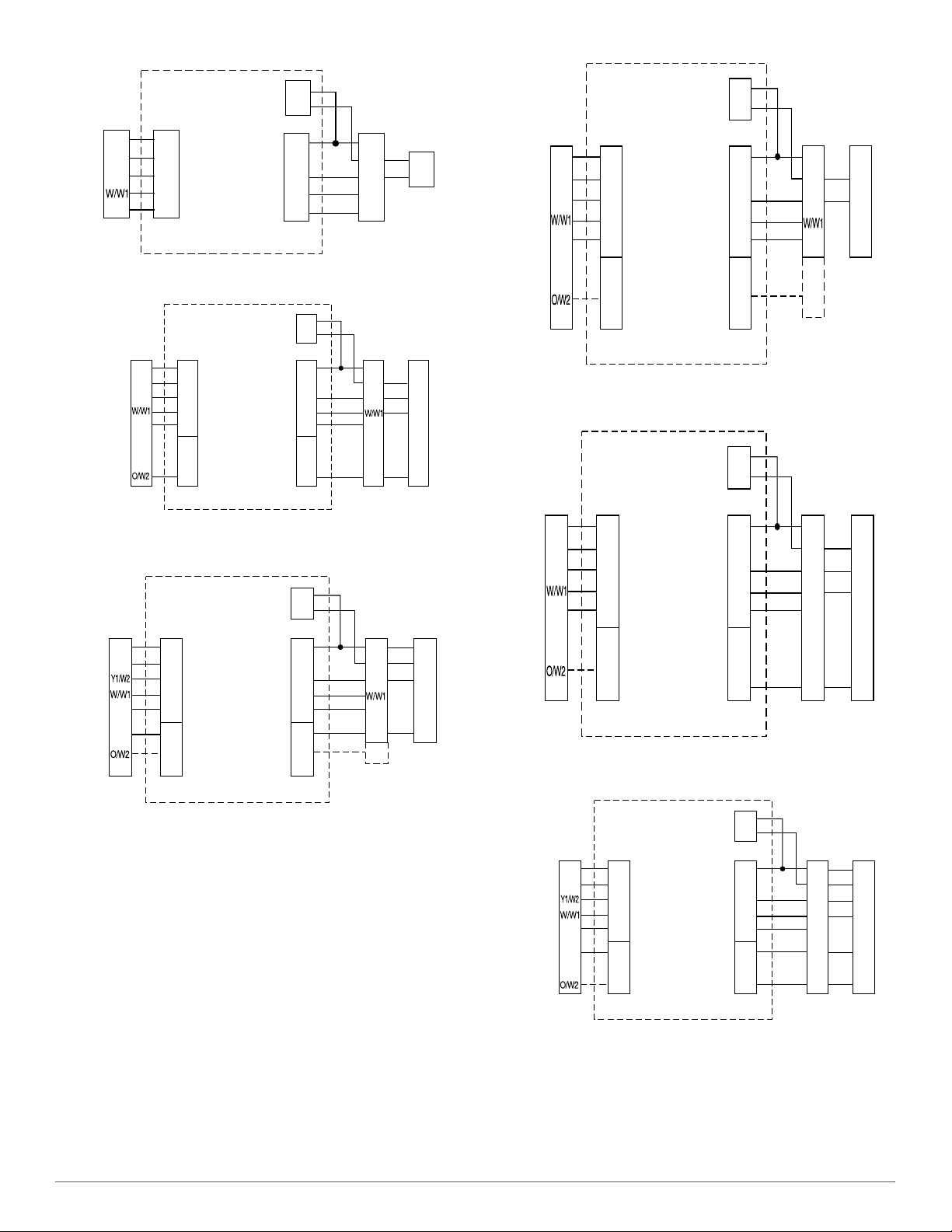
2. Connect the thermostats wires to their respective Zone designation
on the right side of the the 3-Zone Panels. (See Fig. 3).
Step 3 – Install Zone Dampers
Each damper has 3 connections: Close (CLS), Open (OPN), and
Common (COM). Find the connection points along the lower left side
of the 3-Zone Control. Suggested colors are CLS = RED; OPN =
GREEN, COM = WHITE. Field label and make the connections at the
dampers and at the 3-Zone Control. Be careful not to cross zone
numbers.
If duct work required multiple dampers for a single zone, up to 5
dampers may be wired in parallel and may be installed in any position.
WARNING
!
ELECTRICAL SHOCK HAZARD
Failure to follow this warning could result in personal injury or death.
Turn off unit before routing control wiring or any service operation.
Remember, there may be more than one power supply to unit.
CAUTION
!
EQUIPMENT DAMAGE HAZARD
Failure to follow this caution may result in equipment damage.
To prevent possible damage to Bryant 3-Zone System, do not mount
control on plenum, duct work, or flush against furnace.

ZONEBB3Z(AC/HP)01: Quick Reference Guide
Manufacturer reserves the right to change, at any time, specifications and designs without notice and without obligations.
3
Fig. 3 – Wiring Diagram for Installation of Thermostats
A210050
Fig. 4 – Installing Dampers
Step 4 – Install Barometric Bypass Damper
The barometric bypass damper is a critical part of Bryant 3-Zone System
for controlling noise at minimum airflow. A barometric bypass should be
installed unless the duct work and indoor unit have been sized for use
without a bypass. When a direct bypass (outlet air fed back directly into
the return) is used, bypassing decreases entering air temperature in
cooling and increases it in heating. Excessive bypassing will lead to limit
trips, either through the LAT/HPT sensor or the equipment internal
limits.
Step 5 – Install Leaving Air Temperature (LAT) Sensor
/ Heat Pump Temperature (HPT) Sensor (optional)
The Leaving Air Temperature (LAT) sensor is used to detect a cooling
overload condition and is connected to the LAT and LATC terminals.
Polarity does not matter. Locate LAT sensor in main supply trunk after
heating and cooling coil and before bypass damper and first branch.
Cycling on internal equipment limits is to be avoided because it over
stresses and can shorten the life of the equipment. The LAT limit setting
should be selected to trip below the equipment limit.
Fig. 5 – Leaving Air Temperature (LAT) Sensor / Heat Pump
Temperature (TPT) Sensor optional
The HPT sensor is used with ZONEBB3ZHP01 to detect a cooling
overload condition and is connected to the HPT and HPTC terminals.
The HPT sensor will also be monitored in heating to detect a heating
overload condition at the coil with a shutdown temperature of 115°F. It
can be installed through the wall of the fan coil or may be located
entirely inside the fan coil near the blower inlet being careful that it does
not interfere with the blower wheel. If the HPT sensor is not used, the
10K ohm resistor attached to the 2 HPT terminals on the board must be
left in place.
A210068
Zone 1
Thermostate Wiring
Example
A210068
Zone 2
A210067

ZONEBB3Z(AC/HP)01: Quick Reference Guide
Manufacturer reserves the right to change, at any time, specifications and designs without notice and without obligations.
4
Fig. 6 – Leaving Air Temperature (LAT) Sensor
Please refer to Limit Temperature Levels and Actions Table in the
Installation and Start-Up Instructions for additional information on the
response of the system to LAT/HPT sensors.
Step 6 – Connect the Power Supply
Optional: Use a dedicated 24 VAC, 40 VA, 60 Hz isolated transformer
(not included).
Otherwise, if the cooling and heating systems have separate
transformers, twist off the Rc/Rh jumper using a pair of long nosed
pliers. Then connect the R of the cooling transformer to Rc, the R of the
heating transformer to Rh and the common of both transformers to C.
Connect a jumper wire between Rz and Rc. Rc powers G,Y, and O
outputs. Rh power W outputs.
Fig. 7 – Connecting the Power Supply
Step 7 – Wire the HVAC Equipment
The descriptions below and Table 1 will help you choose the connect
wiring diagram for your system. Table 1 also shows the proper setting of
dipswitches 9 and 10 for each diagram.
There are 8 dipswitch settings on the AC zone control and an additional
4 dipswitch on the HP zone controls board. Table 1 summarizes their
function and available settings.
Fig. 8 – Dip Switches
NOTE: ZONEBB3ZAC01 model does
not have HPT connector.
Table 1 – Dipswitch Settings
Dipswitch
Position Operation Description Default (OFF) Optional Settings
1Auto changeover time between heating and
cooling or vice versa
Auto changeover time
ENABLED (OFF) Auto changeover time DISABLED
2Together with dipswitch 3, determines
chanegover time
20 minutes auto changeover
time (OFF) 30 minutes auto changeover time (ON)
3 Multiplier for the modified time set on dipswitch 2 1.0 multiplier (OFF) 0.5 multiplier (ON)
4Installer Test Mode used to check system
operation Normal operation (OFF) Installer Test Mode ENABLED (ON)
5Disables zoning operation with all dampers open
and Zone 1 thermostat as controller
Zoning Operation ENABLED
(OFF) Zoning Operation DISABLED (ON)
6 Setting G (Fan) to energize with W W NOT energized with G (OFF) W energized with G (ON)
7Sets Leaving air Temperature (LAT) limit
temperature (HP/2 Stage control only)
145°F
(OFF)
(OFF) 160°F
(ON) 175°F
(ON)
8130°F
(ON) (OFF)
9Designated Zoning Controller connection to heat
pump (HP) or an air conditioner (AC) 1 or 2 Speed HP / 1 Stage Aux.
Heat (OFF)
1 or 2 Speed
AC / 1 or 2
Stage Heat*
(ON)
*. For 2 stage heating, the stat may be a 2 stage heat AC stat or a HP stat converted to AC.
1 Speed HP / 1
Stage Aux
Heat†
†. Uses an AC stat with 2 stage heating instead of a HP stat.
(OFF)
10 Designates the type of thermostat used with the
Zoning Controller (HP or AC) (ON)
11 Disable over/under temperature protection for the
equipment in emergency situations
LAT and HPT Safety Protection
ENABLED (OFF) LAT and HPT Safety Protection DISABLED (ON)
12 Determine the Reversing Valve is energized for
cooling (O function) or heating (B function)
Reversing Valve energized on
COOLING (OFF) Reversing Valve energized on HEATING (ON)

ZONEBB3Z(AC/HP)01: Quick Reference Guide
Manufacturer reserves the right to change, at any time, specifications and designs without notice and without obligations.
5
A04196
Fig. 9 – AC 3-Zone Control, AC Stat, 1-Stg. AC with 1-Stg. Heat
A04198
Fig. 10 – HP/2S 3-Zone Control, HP Stat, 1-Stg. HP with 1-Stg. Aux.
Heat
A04200
Fig. 11 – HP/2S 3-Zone Control, AC Stat, 2-Spd AC with 1-or 2-Stg.
Heat
A04197
Fig. 12 – HP/2S 3-Zone Control, AC Stat, 1-Stg. AC with 1- or 2-Stg.
Heat
A04199
Fig. 13 – HP/2S 3-Zone Control, AC Stag, 1-Stg. HP with 1-Stg. Aux.
Heat
A04201
Fig. 14 – HP/2S 3-Zone Control, HP Stat, 2-Spd HP with 1-Stg. Aux
Heat
AC 3-ZONE CONTROL
ZONE 1
INPUT
ZONE 1
AC TSTAT EQIUPMENT
POWER
FURNACE
OR
FAN COIL
AIR
CONDITIONER
COOL
HEAT
FAN
RR
C
Y/Y2
G
C
Y1
G
W1
Rc
Y1
G
W1
Rh R
C
Y
G
W
Rz
C
C
Y
H P/2S 3-ZONE CONTROL
ZONE 1
INPUT
ZONE 1
AC TSTAT EQIUPMENT
POWER
FAN COIL HEAT PUMP
HT AND CL
AUX HT
FAN
R
C
Y/Y2
G
Rz
C
REV VALVE
R
C
Y1
G
W1
Y2
W2
O
SWITCH 9=OFF
SWITCH 10=OFF
Rh
Y1
G
W1
Y2
W2
O
R
C
Y
G
C
Y
Rc
OO
W
R
HP/2S 3-ZONE CONTROL
ZONE 1
INPUT
ZONE 1
2SACTSTAT EQIUPMENT
POWER
FURNACE
OR FAN
COIL
LO COOL
(LO) HEAT
FAN
R
C
G
Rz
C
(HI HEAT)
R
C
Y1
G
W1
Y2
W2
O
SWITCH 9=ON
SWITCH 10=ON
Rh
Y1
G
W1
Y2
W2
O
R
C
Y1
G
C
Y1
Rc
R
Y/Y2
HI COOL Y2
W2
Y2
2 SPEED
AIR
CONDITIONER
HP/2S 3-ZONE CONTROL
ZONE 1
INPUT
ZONE 1
AC TSTAT EQIUPMENT
POWER
FURNACE
OR
FAN COIL
AIR
CONDITIONER
COOL
(LO) HEAT
FAN
R
C
Y/Y2
G
Rz
C
(HI HEAT)
R
C
Y1
G
W1
Y2
W2
O
SWITCH 9=ON
SWITCH 10=ON
R
C
Y1
G
W1
Y2
W2
O
R
C
Y
G
W2
C
Y
H P/2S 3-ZONE CONTROL
ZONE 1
INPUT
ZONE 1
AC TSTAT EQIUPMENT
POWER
FAN COIL HEAT PUMP
COOL
HP HEAT
FAN
R
C
Y/Y2
G
Rz
C
AUX HEAT
R
C
Y1
G
W1
Y2
W2
O
SWITCH 9=OFF
SWITCH 10=ON
Rh
Y1
G
W1
Y2
W2
O
R
C
Y
G
C
Y
Rc
OO
W2
R
W
H P/2S 3-ZONE CONTROL
ZONE 1
INPUT
ZONE 1
2S AC TSTAT EQIUPMENT
POWER
FAN COIL
LO HT AND CL
AUX HT
FAN
R
C
G
Rz
C
REV VALVE
R
C
Y1
G
W1
Y2
W2
O
SWITCH 9=ON
SWITCH 10=ON
Rh
Y1
G
W1
Y2
W2
O
R
C
Y1
G
C
Y1
Rc
W2
R
Y/Y2
HI HT AND CL
Y2 Y2
HEAT PUMP
O O
W

© 2021 Carrier. All rights reserved.
A Carrier Company
Edition Date: 04/21 Catalog No: RG-ZONEBB3Z-02
Replaces: RG-ZONEBB3Z-01
ZONEBB3Z(AC/HP)01: Quick Reference Guide
Manufacturer reserves the right to change, at any time, specifications and designs without notice and without obligations.
6
Training
My Learning Center is your central location for professional residential HVAC training resources that help strengthen careers and businesses. We
believe in providing high quality learning experiences both online and in the classroom.
Access My Learning Center with your HVACpartners credentials at www.mlctraining.com. Please contact us a mylearning@carrier.com with
questions.
This manual suits for next models
1
Table of contents
Other Carrier Control System manuals

Carrier
Carrier SmartView User manual

Carrier
Carrier Zone Manager User manual

Carrier
Carrier PRO-DIALOG PLUS 50AZ Manual

Carrier
Carrier PIC 5+ User manual

Carrier
Carrier Infinity SYSTXCCITC-01SI User manual

Carrier
Carrier 3V VVT 33ZCVVTZC-01 Instructions and recipes

Carrier
Carrier SmartVu control Use and maintenance manual

Carrier
Carrier SYSTXCCSMS01-A User manual

Carrier
Carrier i-Vu CCN Pro 4.2 User manual

Carrier
Carrier Zone Manager User manual