Casall INFINITY 1.3X 93013 User manual

1
Casall INFINITY 1.3X
CROSSTRAINER
93013

2
Important: Please locate your serial number and record in the box below for service
support purposes.
Serial number here:

3
S
c
r
e
w
M
3
*
1
4
L
(
2
)
a
l
l
e
n
b
o
l
t
M
8
*
3
0
L
(
2
)
C
u
r
v
e
w
a
s
h
e
r
1
7
.
5
*
2
5
*
0
.
3
T
(
2
)
F
l
a
t
W
a
s
h
e
r
1
6
f
o
r
M
8
b
o
l
t
(
4
)
A
l
l
e
n
B
o
l
t
(
m
o
v
a
b
l
e
h
a
n
d
l
e
b
a
r
)
M
8
*
5
5
(
2
)
S
c
r
e
w
M
3
*
2
5
L
(
8
)
a
l
l
e
n
b
o
l
t
M
8
*
1
2
L
(
8
)
Allen Bolt M7*P1.0*30L(2)
P-1
Regular Washer
7*1t(2)
P-2
Metal cover (1)
P-3
Spring Washer
7*2t(2)
P-4
P-5
P-6
P-8
P-10
s
t
e
e
l
w
a
s
h
e
r
(
2
)
P-11
F
l
a
t
w
a
s
h
e
r
8
*
2
5
*
2
T
(
2
)
P-12
P-13
P
-
1
5P
-
1
4
a
l
l
e
n
b
o
l
t
M
8
*
1
6
L
(
4
)
P-7
A
c
o
r
n
N
u
t
f
o
r
M
8
B
o
l
t
(
2
)
P-9
INFINITY 1.3X

4
Knob (foot pedal)M6*P1.0 (4)
Spring Washer for handlebar bolt 6(black)(4) Carrage bolt M6*P1.0*40L (black)(4)
P-16
P
i
v
o
t
T
u
b
e
(
4
)
P-18
P-17 P-19
A
l
l
e
n
K
e
y
(
2
)
B
o
x
S
p
a
n
n
e
r
(
1
)
INFINITY 1.3X

5
Assembly Diagram
K-1

6
EXPLODED DIAGRAM
H-8

7
PARTS LIST
No. Item spec. Q'ty
A , A-1 Computer & Screw for computer 1SET
A-3 Chest belt 1PC
B-1 Front handlebar 1PC
B-2 Foam grip for front handlebar 2PCS
B-3 End cap for foam grip φ7/8" 2PCS
B-4 Hand pulse WP1007-33B 1SET
B-5 Screw M3x20L 2 PCS
B-6 Wire for hand pulse 1 PC
C-1 Upper handlebar ( L) 1SET
C-2 End cap for upper handlebar (R&L) φ1 1/4" 2PCS
C-3 Foam grip for upper handlebar 2PCS
C-4 Upper handlebar ( R) 1PC
D-1 Handlebar post 1PC
D-2 Upper computer cable 1PC
D-3 Screw for computer cover M5x14L 2PCS
D-4 Bushing 2PCS
D-5 Allen bolt M8x16 4PCS
D-6 Flat washer φ12xφ19x1t 4PCS
D-7 Screw for bottle holder M5x20L 4PCS
E-1~E7 First-lower handlebar (R& L) 1SET
F-1 Main frame 1SET
F-2 C-type ring φ12 1PC
F-3 Wave washer φ20xφ30x0.3t 1PC
F-4 Flat washer φ20.3xφ30x1t 1PC
F-5 Sensor box 1PC
F-6 Sensor holder 1PC
F-7 DC cable 1PC
F-8 Screw M4x10L 1PC
F-9 Bearing 6004RS 2PC
G1~G-8 Flywheel set 1SET
H Magnetic set & Gear box 1SET
I-1 Pedal post (Left) 1PC
I-2 Screw M5x14L 4PC
I-3 Pedal post (Right) 1PC
J-1~J-3 Front stabilizer set 1SET

8
K-1~K-3 Rear stabilizer set 1SET
L-1~L-11 Idler wheel set 1SET
M-1 Front cover for computer 1PC
M-2 Rear cover for computer 1PC
M-3 Bottle holder 1PC
M-4 Front cover (Left) for pedal post 2PCS
M-5 Front cover (Right) for pedal post 2PCS
M-6 Pedal (Left) 1PC
M-7,M8 Left rear cover (upper/down) for pedal post 1SET
M-9 Pedal (Right) 1PC
M-10,M-11 Right rear cover (upper/down) for pedal post 1SET
M-12 Screw for chain cover M4x50L 5PCS
M-13 Screw for chain cover M5x16L 6PCS
M-14 Left chain cover 1PC
M-15 Right chain cover 1PC
M-16 Cap for chain cover screw holes Oval 5PC
M-17 Cap for chain cover screw holes Round 4PC
M-18 Cover for handlebar post 1PC
M-19 Axle for first-lower handlebar 1PC
N Adaptor 1PC
P-1~P-19 Bolts & nuts pack 1SET
Q-1 Shaft 1PC
Q-2 Bushing φ20.5xφ25x7.5mmL 1PC
Q-3 Hexagonal screws M8xP1.25x12Lx5t 3PCS
Q-4 Big pulley 1PC
Q-5 Belt J6 1219m/m 1PC
R-1 Nut M10xP1.25x10T 2PC
R-2 Cross disc 2PCS
R-3 Round disc 2PCS
R-4 Screw M4x14L 8PCS
R-5 Flat washer φ5xφ16x1t 9PCS
R-6 Cap for round disc 2PCS
S-1~S-8 Crank connation set 2SET
9
ASSEMBLY STEPS
STEP 1
Attach the Front Stabilizer (pt.J-1) to the Main Frame (pt.F-1) using two Allen bolt (pt.P-7)
Attach the Rear Stabilizer (pt.K-1) to the Main Frame (pt.F-1) using two Allen bolt (pt.P-7).
.
STEP 2
1. Please remove four sets of the M8x16 Allen bolt (pt.D-5) and Flat Washer (pt.D-6)from the
Main Frame (pt.F-1)
2. Take the Handlebar post (pt.D-1) and pass it through the Handlebar post cover (pt.M-18).
3. Hold the Handlebar Post (pt.D-1) and connect the Lower Computer Cable (pt.H-14) and
the Upper Computer Cable (pt. D-2)
4. Slide the Handlebar Post (pt.D-1) into the Main Frame then fix with four sets of M8x16
Allen bolt (pt.D-5) and Flat Washers (pt.D-6).
M8*16L
4* 1* K
-
1
12* 19*1T M8*16L
4* 1*

10
STEP 3
1. Attach the Front handlebar (pt.B-1) to the Handlebar post (pt.D-1) using the clamp cover
(pt.P-3), and then fix with two Flat Washers (pt.P-2), two Spring Washers (pt.P-4), two
Fixing Bolt (pt.P-1).
2. Pass the hand-pulse wire (pt.B-6) through the hole.
3. Connect the Computer cables (pt .D-2) and connect the Hand pulse wire (pt.B-6), then
attach the Computer (pt .A-1) to the Computer bracket with the enclosed Screws (pt .A-2).
2* 7*2T 7*1T M7*30
M5*10
4*1*
1*

11
STEP 4
1. Remove the pre-installed Screws (pt.D-3) on the handlebar post first.
2. Attach the Rear cover (pt.M-2) using two of Screws (pt.P-6) and one of Screws (pt.D-
3) .
3. Attach the Front cover (pt.M-1) using Screws (pt.D-3)
4. Remove the pre-installed Screws (pt.D-7) on the handlebar post, and then assemble the
Bottle holder (pt.M-3) by Screw (pt. D-7).
1*
M5*14
2* M5*20
2*

12
STEP 5 Fix the two Lower handlebar (pt.E-1) to the Handlebar Post (pt.D-1) with one
Axle (pt.M-19), two sets of Wave washer (pt.P-13), Flat washers (pt.P-12) and
Gasket (pt.P-11) and Allen bolt (pt.P-10).
Pay attention : Please use two allen key tools to fix bolt ( P-10 ) on both side at the same
time.
M8*30L
steel washer
2* 1*
17.5* 25*0.3T
10* 26*2T

13
STEP 6
1. Attach the Left and Right lower Handlebar (pt.E-1 L/R) to the Left and Right pedal post
(pt.I-1 & I-3) using two Allen bolt (pt.P-14), four Flat washers (pt.P-15) and two Nylon
nuts (pt.P-9). --- Figure A
2. Attach the Pedal post (pt.I-1 & I-3) onto the Crank connation set using one of Nylon nuts
(pt.S-4), Flat washers (pt.S-3) and Plastic washers (pt.S-8). --- Figure B
3. Connect the Right rear cover (upper) (pt.M-8) and Right rear cover (lower) (pt.M-7) to the
Left pedal post (pt.I-1) using screw (pt.P-5). --- Figure C
4. Connect the Left rear cover (upper) (pt.M-10) and Left rear cover (lower) (pt.M-11) to the
Right pedal post (pt.I-3) Using screw (pt.P-5).
M8*55
M3*25L
M8
M8
2*
4*
6*
1*
A
B
C
D

14
M5*14
M3*25L
6 M6*P1.0*40L M6 7X 12X25
4* 2* 4* 1*
E-1
STEP 7
1. Remove the pre-installed screws (pt.I-2) on the Pedal post first.
2. Attach the Lower handlebar (E-1 R/L) to the left and right pedal post (I-1), and then close
the cover (M-4 & M-5) using screws (pt.P-5 & I-2).
3. Assemble the Right pedal (pt.M-9) onto the Pedal post (pt. I-3) with 2 Knobs (pt. P-16), 2
Spring washers (pt.P-18),2 Bushings (pt.P-19) and 2 Carriage bolts (pt.P-17).
4. Assemble the Left pedal (pt.M-6) onto the Pedal post (pt. I-3) with 2 Knob (pt. P-16), 2
Spring washers (pt.P-18),2 Bushings (pt.P-19) and 2 Carriage bolts (pt.P-17).
STEP 8 Slide the Upper handlebar post (C-1,C-4) (R/L) into the Lower handlebar (E-1) and
then fix with the eight Allen bolts (P-8)
M8*12L
8*
1*
E-1

15
STEP 9
Connect the adaptor (N) to the DC hole (located on the back of the chain cover).
I
In
ns
st
tr
ru
uc
ct
ti
io
on
n
m
ma
an
nu
ua
al
l
o
of
f
t
th
he
e
t
tr
ra
an
ns
sm
mi
it
tt
te
er
r
b
be
el
lt
t
f
fi
it
tt
ti
in
ng
g
1
1.
.
T
Ti
ig
gh
ht
tl
ly
y
W
Wr
ra
ap
p
t
th
he
e
t
tr
ra
an
ns
sm
mi
it
tt
te
er
r
b
be
el
lt
t
a
ar
ro
ou
un
nd
d
t
th
he
e
c
ch
he
es
st
t
a
ar
re
ea
a.
.
(
(T
Th
he
e
b
be
el
lt
t
w
wo
ou
ul
ld
d
o
on
nl
ly
y
w
wo
or
rk
k
w
wi
it
th
h
d
di
ir
re
ec
ct
t
c
co
on
nt
ta
ac
ct
t
t
to
o
t
th
he
e
s
sk
ki
in
n)
).
.
2. Adjust the belt to the position shown on the sketch.
3. The distance between the belt and the monitor should be
80cm ±10. Make sure user is directly in front of the monitor
at all times.
Connection the Tunelinc wire
Please connect the wire of Tunelinc to the audio port on the mobile phone or pad as
illustrated drawing.

16
SM2564‐71andiConsole+AppINSTRUCTIONMANUAL
System plug connection
socket
Connection for mobile
phone or pad
Connection for hand pulse wire

17
!!!Forsimpleexercise,itisnotalwaysnecessarytoselectatrainingprogramormanuallysettheTIME,DISTANCEor
othervalues.Youcansimplystartpedaling.
Assoonasthecomputerisconnectedwithpowersupply,anacousticsignalsoundsandallofthedisplaysareshownon
LCDfor2seconds.Thenwheeldiameter(78.0)willbeshownbriefly,aswellasunitKM(K)textwoulddisplayontheright.
DISPLAYSandBUTTONFUNCTIONS
TrainingValuesDisplayRangeSettingRange
TIME0:00~99:59min.0:00~99:00min.
SPEED0.0~99.9KM/
DISTANCE0.0~99.9KM0.0~99.0KM
CALORIES0~999Cal.0~990Cal.
WATT0~999W10~350W
RPM(Revolution/min.)0~999/
PULSE30‐230BPM0‐30`230BBPM
AcousticSignals
Allsettingsmadewiththecomputerareconfirmedwithanacousticsignal:
1shotbeep=settingconfirmed
2shotbeeps=Itisimpossibletomakeanysettings
(forexample,atrainingprogramisrunning;pressSTART/STOPtoendtheprogram.)
TrainingData
Thecomputercalculatesanddisplaysallvaluesautomaticallyaccordingtousertrainingstatus(seetable).
Takenote:
*Ifonlya“P”isshowninsteadofpulsevalue,itisimpossibletomeasurethepulse.Gripthehandlewhere
allfourhandpulsesensorsarelocatedorwearcheststrap.Moistenyourpalmsfirstwithalittlewaterif
necessary.
BUTTONFUNCTION
Jogglewheel‐Increase/DecreaseValue
‐Confirm/Settingselection.
Reset‐Holdonpressingfor2seconds,computerwillrebootandstartfromusersetting.
‐ResetallvaluestozeroduringsettingworkoutvalueorStopmode.
Start/Stop‐StartorStopworkout.
Recovery‐TrackuserHeartrateinrecoveryphase.
Bodyfat‐MeasureuserBodyfatpercentageandBMI(BodyMassIndex).
50
%
70
%
80
%
Max
65
%
75
%
50
%
70
%
80
%
Max
65
%
75
%

18
.
*Thedisplayinthecenterfielddependsonthetypeofexercisethathasbeenset.
Thecomputerprovidesanumberofwaystovarytheexercisesessionandmakeitmoremotivating.
Thefollowingexercisingareavailable:
‐ManualTraining(trainingwithoutprograms)
‐TrainingwithPrograms(thereare12programsbuilt‐in,P01~P12)
‐Trainingwithyourownprogram(Userprogram)
‐TrainingwiththeHeartRateprogram(H.R.C)
‐Trainingwithsetoutputvalue(WATT)
Startingexerciseimmediately(Manual)
Onceapowerconnectionhasbeenestablished,thecomputerwillrequirestocreateyourownprofile.
RotateandpressjogglewheeltoenterUSERsetting(forBODYFATfunction),settingpersonaldatain
U1~U4.Pressjogglewheeltogotoworkoutselectionmode.
MANUALisflashinginmatrixdisplaywith1Hz.Ifyouhavepreviouslyselectedaprogramorstartedyour
workout,pressRESETtoreturntothestartingdisplay.
‐PressSTART/STOPbuttontostartworkoutimmediatelywithoutenteringfurthersettings.
‐Pressjogglewheeltoenteryourpersonalsettings:thefollowingfieldswillflashinturn
.TIME
.DISTANCE
.CALORIES
.PULSE
Rotatejogglewheelupordowntosetvaluesandconfirmyourselection.
Hand sensor
for measurement

19
PressSTART/STOPtostartworkout.
AssoonasoneofthesetvaluereachthepresetTarget,theiconwillflashintheappropriatedisplay
window(e.g.TIME)andseveralbeepssound.
‐Youcanadjustthelevelofresistanceonthepedalswhileexercisingbyrotatingjogglewheelupordown.
ThenewlysetvaluewillbeshownundertheLOADwindow(defaultvalueisLevel1).WithoutKEYentryfor
3seconds,theLoadlevelvaluewillchangetoWATTvalue.
‐PressSTART/STOPtoendexercising.Allexercisingvaluewillremain(HRsignalwouldnoteffect).
SelectingaProgramtodotraining
Onceapowerconnectionhasbeenestablished,MANUALisflashinginthedisplay.
‐RotatejogglewheeltogobetweenM(Manual)→P(Program)→♥(H.R.C.)→W(Watt)→U(User)cyclically.
‐ChooseP(Program)andpressjogglewheeltoconfirm.Theprogramsarepresetwithprofiles.Rotatethejoggle
wheeltoselectonefromthe12presetprofiles.Setthedesiredsessiontimewithjogglewheelpress
STATR/STOPtostartworkout.
‐Youcanadjustthelevelofresistanceonthepedalswhileexercisingbyrotatingjogglewheelupordown.
ThenewlysetvaluewillbeshownundertheLOADwindow.WithoutKEYentryfor3seconds,theLoad
levelvaluewillchangetoWATTvalue.
‐Programexplain:
IntervalprogramsP2‐P3‐P7‐P12
IncreasingresistancelevelprogramsP6‐P9‐P11
IncreasinganddecreasingresistancelevelprogramsP1‐P4‐P5‐P8‐P10
Thestoredtrainingprogramsaredesignedespeciallytoenhanceaerobicbasefitness.
.Asabeginneryoushouldstartwiththoseprogramsslowlyandsetalowpedalresistance.
.YoushouldonlygraduatetoIntervalprogramsonceyouhavebeentrainingforseveraltimes.
Setprogramaccordingtoheartrate(H.R.C.)
Inthisprogram,theexercisebikereactstoyourpulseasmeasuredbythehandsensorsorchestbelt.
Thisprogramsallowsyoutoexerciseefficientlyandsafelywithinyourrequiredheartratezone.
Inaddition,simplegraphicsalsoshowyouwhetheryouneedtoneedtoincreaseordecreaseyourstress
Level.Youcanchoosebetween:
HRC55Hereyouareexercisingintheveryefficientrangeof55%,idealforbeginnersandforgeneralfat
Burning.

20
HRC75Thisrangeof75%ofthemaximumpulserateissuitableforexperiencedusersandathletes.
HRC90Theanaerobicrangeof90%ofthemaximumpulserateisonlysuitableforcompetitiveathletes
andshortsprintexercises.
TAGThecomputerusesyourAgetocalculateatargetpulserate,whichyoucanchangeasperyour
willing.Neverselectatargetpulsethatishigherthanyourage‐determinedmaximumpulserate.
‐PressjogglewheeltoselectH.R.C.andenterbypressingit.ChooseHRC55‐‐>HRC75‐‐>HRC90‐‐>TARGET.
WithHRC55,HRC75,HRC90,themax.Heartratewillbecalculatedbythecomputerautomatically.
‐WiththeTARGETprogram,thepresetvalue100willbeshown.Rotatejogglewheeltosetavalue
between30~230andconfirm.Theprogramhasbeensaved.
‐SetthedesiredsessiontimewithjogglewheelandpressSTATR/STOPtostartworkout.
Forthisprogram,itisnecessarytokeepyourhandsonthesensorgripsorwearcheststrapwhile
exercisingsothatcomputercandetectanddisplayyourheartratevalue.
Programsequence:
Thecomputersetsapedalresistancethatkeepsyouexercisingconstantlywithinyourtargetpulserate.
.Ifyouareexercisingandgobelowyourpresetpulserate,thepedalresistancewillautomaticallyriseby
onestresslevelevery30seconds.
.Ifyouareexercisingandgoaboveyourpresetpulserate,thepedalresistancewillautomatically
decreasebyonestresslevelevery15seconds.Ifyouhavealreadyreachedthelowestlevel“1”andyour
pulserateisstillhigherthanyourpresetvalue,thenafterabout30secondsanacousticsignalwillalarm
andcomputerprogramwillendautomatically.
Exercisingwithsetoutputvalues(Watt)
Hereyoucanenteraconstantoutputvalue.Thecomputerautomaticallyadjuststhepedalresistanceto
yourspeedsothatyouroutputremainsconstant.
‐PressjogglewheeltoselectWATTandenterbypressingit.Rotatejogglewheeltosetdesiredsession
outputvalue(defaultvalue:120).
‐SetthedesiredsessiontimewithjogglewheelpressSTATR/STOPtostartworkout.
‐YoucanadjustWATTlevelwhileexercisingbyrotatingjogglewheelupordown.Thenewlysetvaluewill
beshownundertheWATTwindow.WithoutKEYentryfor3seconds,theLoadlevelvaluewillchangeto
WATTvalue.
Table of contents
Other Casall Fitness Equipment manuals

Casall
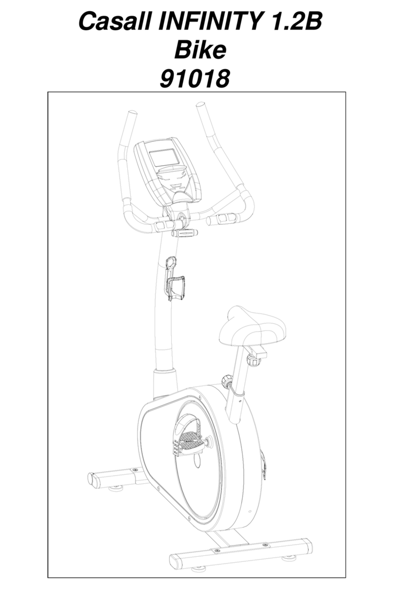
Casall Infinity 1.2B User manual

Casall
Casall R300 II User manual

Casall
Casall X250 User manual

Casall
Casall PT1 Power Trainer Installation and operating instructions

Casall
Casall R600 II User manual

Casall
Casall INF 2.0 PLUS User manual

Casall
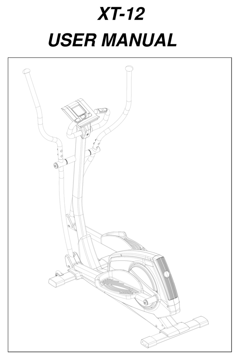
Casall XT12 User manual

Casall
Casall INF 2.0 PLUS User manual