Casall PT1 Power Trainer Installation and operating instructions

Inspire, By Casall
ASSEMBLY & OPERATION MANUAL
RECORD SERIAL NUMBER HERE
www.inspirefitness.net Dec. 2010
PT1
Power Trainer

TABLE OF CONTENTS
Section Description.......................................... ..
Page
Instructions ...................................................... ..
1
Tools Required ....................................................
1
Parts & Hardware List......................................... ..
2-4
Hardware Sizing Chart......................................... .
5-6
Assembly Instructions ......................................... ..
7-28
Exploded Diagram ............................................... .
29
Decal Reference ..................................................
30
General Maintenance Information ........................
31
Maintenance Schedule...
32
Limited Warranty.................................................
33

BEFORE ASSEMBLING YOUR Power Trainer
IMPORTANT: Read this entire manual before attempting to build or use this
product. This manual contains step by step instructions for proper assembly.
Use the parts list included in this manual to verify that all parts are
accounted for before assembly. If any parts are missing, contact the retailer
of this product for replacement parts. Or, visit service.casall.se for more
information.
Service of your home gym should only be preformed by an authorized
INSPIRE retailer. Service preformed by anyone else can result in loss of
warranty. Use only Inspire replacement parts on this machine. The use of
any other brand of parts can also result in a loss of warranty. If you need
help finding an authorized retailer, please contact us directly:
Sweden Head office
Casall Sport AB
Västgötegatan 7
Box 6007
600 06 Norrköping
Sweden
Phone: +46 (0) 11 32 56 00
Fax: +46 (0) 11 32 56 10
info@casall.se
REGISTER YOUR GYM ON LINE AT WWW.INSPIREFITNESS.NET
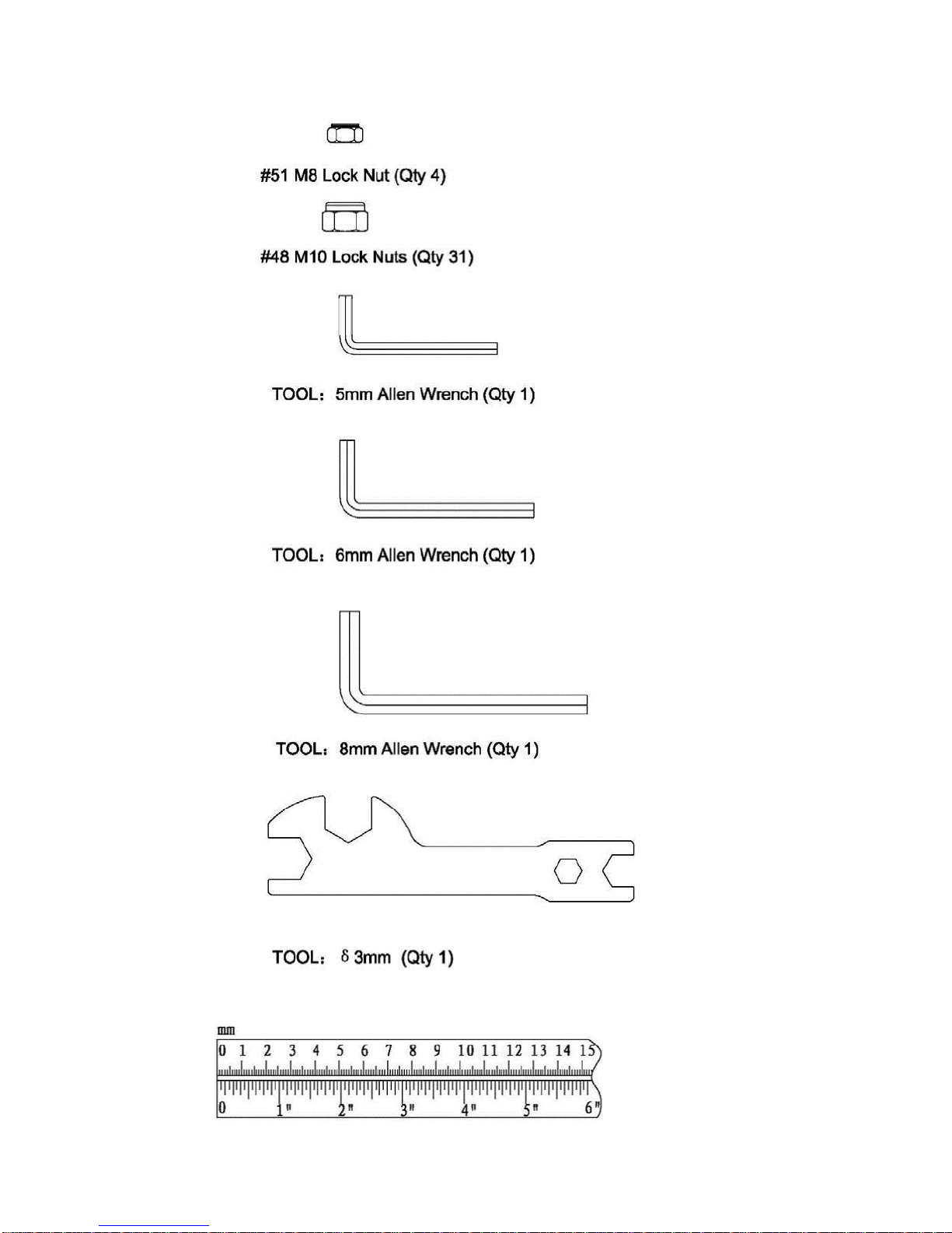
TOOLS REQUIRED FOR ASSEMBLY
Metric socket set
Adjustable wrench
Tape Measure
Rubber Mallet
PAGE 1

Part List for Power Trainer
Part#
Description
Spec.
Q'ty (pcs)
说明
1
Main Base
1
2
Main Upright
1
3L
Left Leg
1
3R
Right Leg
1
4L
Left Support Arm
1
4R
Right Support Arm
1
5
Cross Brace
1
6
Top Beam
1
7
Lat Bar Assembly
1
8R
Right Handlebar Assembly
1
8L
Left Handlebar Assembly
1
9
Connector Plate
1
10
Arm Cushion
2
11
Backrest Cushion Assembly
1
12
Backrest Cushion Hanging plate
1
13
U Bracket
2
14
Backrest Cushion Protection Plate
1
15
Backrest Cushion Limit Plate
1
16L
Push Up Tube(Left)
1
16R
Push Up Tube(Right)
1
17
Washer
Φ30*Φ11*2.5
6
Black Zinc Plated
18
Pulley
27
BLACK
19
Top cover
1
BLACK
20
Locknut
M6
2
Black Zinc Plated
21
Rubber Plate
53*32*2
5
BLACK
22
Foot Cushion
M10*30
3
BLACK
23
Rubber Cushion
Fit with φ25.4 round tube
2
BLACK
24
End cap
Assembly
1
25
Handlebar Grip
Φ33*Φ21*310
2
BLACK
26
End cap
Fit with Φ50.8 round tube
2
BLACK
27
Handlebar Grip
Φ33*Φ21*152
2
BLACK
28
End cap
fit with 75*50*2 tube
3
BLACK
29
EVA PAD
100*25*2
4
BLACK
30
Push Up tube Grip
Φ30*Φ24*350
2
BLACK
31
Hexagon socket button head screws
M10*30
7
Black Zinc Plated
32
Hexagon socket button head screws
M10*105
3
Black Zinc Plated
33
Hexagon socket button head screws
M10*85
2
Black Zinc Plated
34
Half-head inner hexagon screw with shoulder
M8*40
4
Black Zinc Plated
35
Hexagon socket button head screws
M10*100
2
Black Zinc Plated
PAGE 2

Part List continued Power Trainer
36
Hexagon socket button head screws
M10*20
6
Black Zinc Plated
37
Flat-head inner hexagon screw with shoulder
φ12*93*M10
1
Black Zinc Plated
38
Hexagon socket button head screws
M8*15
4
Black Zinc Plated
39
Hexagon socket button head screws
M10*70
5
Black Zinc Plated
40
Hexagon socket button head screws
M10*125
2
Black Zinc Plated
41
Pan head screws with cross recess
M10*50
13
Black Zinc Plated
42
Hexagon socket button head screws
M8*20
10
Black Zinc Plated
43
Flat Washer
φ10
90
Black Zinc Plated
44
Spring Washer
φ10
8
Black Zinc Plated
45
Flat Washer
φ8
12
Black Zinc Plated
46
Flat Washer
φ12
1
Black Zinc Plated
47
Flat Washer
φ5
4
Black Zinc Plated
48
Locknut
M10
59
Black Zinc Plated
49
Hexagon socket button head screws
M10
2
Black Zinc Plated
50
Pulley distance sleeve
Φ20*Φ11*6
4
Black Zinc Plated
51
Locknut
M8
4
Black Zinc Plated
52
Guide Rod Spacer
1
53
Bottom Shroud Plate
2
BLACK
54
Weight Stack Raisers
2
55
Rubber Donuts
φ64*φ20*25.5
2
BLACK
56
Weight Selector Pin
1
57
Weight Plate
15
BLACK
58
Selector Stem
Φ22*582
1
Chrome Plated
59
Cap Weight
1
BLACK
60
Guide Rod
Φ19*2008
2
Chrome Plated
61
U-shaped Pulley Bracket
1
62
Upper Cross Brace
1
63
Upper Pulley Bracket Assembly
1
64
Rear upright tube
1
65
Cable Adapter
2
66
Floating Pulley Bracket
2
67
Cable Stoper
2
BLACK
68
Cable Guide Bracket
2
69
Rear Stabilizer
1
70
Pulley Plate
2
Chrome Plated
PAGE 3

Part List continued Power Trainer
71R
Upright tube assembly R
1
Chrome Plated
71 L
Upright tube assembly L
1
Chrome Plated
72
Adjusting grip
Φ33*Φ21*140
2
BLACK
73
Handle Assembly
2
74R
Adjusting Sleeve Assembly -R
1
74L
Adjusting Sleeve Assembly -L
1
75
Carriage Sleeve
4
BLACK
76
T-shaped Lock Pin
2
77
Rubber Plate
37*20*3
4
BLACK
78
Storage Hanger Bushing
Φ25.4*Φ21.4*Φ12*15
4
79
Pulley Bracket
2
80
U-Bracket Cable End
2
Chrome Plated
81
Bushing
Φ13*Φ10*Φ6.2*4.5
2
82
Lower Bracket Assembly
2
83
Foot Plate
1
84
Rear Cable
1
85
Cable
2
86
Fabric Chain Cover
1
87
Hexagon socket button head screws
M10*95
2
Black Zinc Plated
88
Hexagon socket button head screws
M10*45
6
Black Zinc Plated
89
Hexagon socket button head screws
M10*40
1
Black Zinc Plated
90
Hexagon socket button head screws
M10*40
4
Black Zinc Plated
91
Hexagon socket button head screws
M10*100
3
Black Zinc Plated
92
Hexagon socket button head screws
M10*130
2
Black Zinc Plated
93
Hexagon socket button head screws
M10*80
2
Black Zinc Plated
94
Hexagon socket button head screws
M10*145
2
Black Zinc Plated
95
Hexagon socket button head screws
M10*75
4
Black Zinc Plated
96
Flat-head inner hexagon screw with shoulder
φ12*63*M10
2
Black Zinc Plated
97
Half-head inner hexagon screw with shoulder
M6*32
2
Black Zinc Plated
98
Hexagon socket button head screws
M10*35
2
Black Zinc Plated
99
Hexagon socket button head screws
M10*55
2
Black Zinc Plated
100
End cap
Fit with 60*30*1.5 ellipse tube
101
Washer
Φ26*Φ10*2
22
Black Zinc Plated
102
Allen Head Screw
M12
1
Black Zinc Plated
103
Rubber Plate
35*20*2
4
BLACK
104
End cap
Fit with φ25.4*2 ellipse tube
2
BLACK
Hex key wrench
5#
1
Zinc Plated
Hex key wrench
6#
1
Zinc Plated
Hex key wrench
8#
1
Zinc Plated
thin wrench
δ3
1
Zinc Plated
PAGE 4

Hardware Sizing Chart
PAGE 5

Hardware Sizing Chart Continued
PAGE 6

STOP! VERY IMPORTANT:
To assemble the Inspire Fitness PT1, follow the hardware
listing for the PT1 on the three hardware boards. The
hardware needed for a step might be located on more than
one board. For Example: the hardware for Step 1 is found
on two separate boards.
On one board the hardware is listed as:
CDVK2-Step 1
PT1-Step 1
On the other board the hardware is listed as:
PT1-Step 1
PAGE 7

Step 1
Attach Right & Left Legs (#3R & 3L) to Main Upright (#2) & Main Base (#1) using:
One (M10 x 4/5” Bolt)
Three (M10 x 4 1/8” Bolt)
Attach Rear Stabilizer (#69) to Main Base (#1) using: Three (M10 x 3 3/4” Bolts)
Note: Finger Tighten Only
Page 8 12/10

Step 2
Attach Left & Right Support Arms (#4L & 4R) to Main Upright (#2) using:
Two (M10 x 4” Bolts)
Attach Both Support Arms (#4L & 4R) and the Foot Plate (#83) to the Legs using:
Two (M10 x 3 3/8” Bolts)
Attach Foot Plate (#83) to Left and Right Legs (#3L & 3R) Using:
Two (M10 x 3 1/8” Bolts)
Attach Cross Brace (#5) to Support Arms (#4L & 4R) Using: Four (M8 x 1 3/5” Bolts)
Note: Wrench Tighten Steps 1 thru 2 now.
Page 9 12/10

Step 3
Attach Guide Rods (#60) to Main Base (#1) Using: Two (M10 x 1 3/5” Bolts)
Note: Finger Tighten Only
Page 10 12/10

Step 4
Step 4: Attach Bottom Shroud Plate (#53) and Guide Rod Spacer (#52) to Main Base Using:
Two (M10 x 2 1/8” Bolts)
Note: Wrench Tighten Steps 3 & 4 Now.
Page 11 12/10

Step 5
Attach U Shaped Pulley Bracket (#61) and pulley to Selector Stem (#58). IMPORTANT! Thread U
shaped Pulley bracket bolt halfway into Selector Stem and tighten Jam Nut securely.
NOTE: Before beginning Step 5: If optional 200 lb. heavy weight stack is being assembled, eliminate the
Weight Stack Risers(#54). (This space will be taken up by 5 extra weight plates.)
Slide Weight Stack Risers (#54) down the Guide Rods (#60) and onto the Shroud Plate. Next slide the
Rubber Donuts (#55) down the Guide Rods until sitting on Weight Stack Risers. Next slide each plate
down the Guide Rods until all 15 Weight Plates (#57) are resting on the Rubber Donuts.
Be sure that all weight plates are facing forward and right side up. (Front of each weight plate is signified
by recessed area for weight stack numbers. The bottom of each plate has three raised feet).
Page 12 12/10

Step 6
Attach the Upper Shroud Plate (#53) to the Shroud Plate Mount (#62) by threading the
three Button Head Screws half way down threaded barrels.
NOTE: Be sure that all three Button Head Screws are threaded to an equal depth.
Page 13 12/10
NOTE: Upper Shroud Plate has three
4” bolts pre-installed.

Step 7
Attach Shroud Plate Mount (#62) to Top Beam (#6) Using: Two (M10 x 2 3/4”
Bolts) Slide Shroud Plate Mount (#62) onto the Guide Rods (#60)
Attach Top Beam (#6) to Main Upright (#2) Using: Two (M10 x 2 3/4”
Bolts) Note: Finger Tighten Only.
Page 14 12/10

Step 8
Attach Guide Rods (#60) to Top Beam Assembly (#6) Using: Two (M10 x 1 3/5” Bolts)
Note: Finger Tighten Only.
Page 15 12/10

Step 9
Attach Lat Bar Assembly (#7) to Top Beam Assembly (#6) Using: Two (M10 x 4 7/8” Bolts)
Note: Wrench Tighten This Step Now.
Page 16 12/10

Step 10
Attach Right & Left Handlebars (#8R & 8L) to Main Upright (#2) Using:
One (M12 x 3 5/8” Bolt)
Attach Right Handlebar (#8R) and Left Handlebar (#8L) to Connector Plate using:
Four (M8 x 3/5” Bolts)
Note: Wrench Tighten This Step Now.
Page 17 12/10

Step 11
Attach Arm Cushions (#10) to Right & Left Handlebars (#8R & 8L) Using:
Four (M10 x 4/5” bolts)
Note: Wrench Tighten This Step Now, But Do Not Over Tighten.
Page 18 12/10
Table of contents
Other Casall Fitness Equipment manuals